JAIC 1987, Volume 26, Number 2, Article 1 (pp. 65 to 73)
CRITERIA FOR TREATMENT: REVERSIBILITY
Barbara Appelbaum
ABSTRACT—The author reconsiders the “Principle of Reversibility” by clarifying its definition and by examining the variables that make a treatment reversible. Different criteria for different parts of a treatment are
recommended. The relationship between cleaning and reversibility is examined. There are degrees of reversibility; even irreversible treatments should be considered in terms of whether they allow for future treatment (“re-treatability”).
The “Principle of Reversibility”1 is one of the basic tenets of the modern field of conservation. The Code of Ethics of the American Institute for
Conservation, however, was written mainly with the treatment of paintings in mind. Clearly, varnishing and inpainting are expected to be reversible
processes. And, when the Code was written in the 1960s, wax linings were such an improvement over glue linings that we can assume that the
reversibility of the lining process was not considered in any way problematic.
Reversibility is still a major criterion of good conservation treatment, one that sets conservators apart from skilled restorers or repairers. The “Principle of Reversibility” is one of the factors which establish our unique intent to project our work into the distant future. Conservators have an obligation to assure to the best of their ability that the condition of an object remain unchanged long after treatment is completed. Knowledge of how conservation materials age, how they interact with the object, and how the object responds to its
environment is therefore necessary to fulfill this obligation.
Since the Code was promulgated, there has been little discussion about the meaning of reversibility in relation to treatments other than those of paintings, although the principles in the Code have since been applied to the treatment of a much wider range of materials, including machinery and whole buildings. The range of treatment materials and techniques has also expanded
tremendously. It is important, therefore, to examine the idea of reversibility in relation to all parts of a treatment, to many different kinds of objects, and to a wide variety of treatment techniques.
“Reversibility” is often used inaccurately as a catch-all term for a variety of treatment criteria. These include such varied issues as the appropriateness of a treatment material to the aesthetic requirements of the object and the
1 TERMINOLOGY
In order to be as clear as possible about the meaning of the term “reversible,” it is important that conservators confine its use to the description of a process rather than of a material. The idea that a material can be reversible is not logical. The incorrect use of “reversibility” to mean “solubility” as applied to resins has however become common. It is certainly tempting to refer to a material like Acryloid¯B-72, for example, as a “reversible material” in order to indicate a group of properties which we find desirable. These include
chemical inertness, unchanging solubility over long periods of time, durability, and lack of color changes. However, the use of the term “reversibility” to cover all of these properties may produce serious error if it leads us to assume that any treatment using a soluble material is a reversible one, or that any use of an “approved” conservation material constitutes a proper treatment.
In order to avoid this confusion, I propose that Robert Feller's terminology for describing the photochemical stability of thermoplastic resins2 be put into common use and extended to other conservation materials. Acryloid¯B-72 and the polyvinyl acetate resins can then be referred to as Class A materials, with a useful lifetime of over one hundred years, polybutylmethacrylate (e.g.,
Elvacite¯ #2044) as a Class B material, with a useful lifetime of twenty to one hundred years, etc. This terminology is particularly meaningful because, unlike many terms we take from other fields, it describes our particular needs for long-term stability, requirements much more stringent than those of the industrial fields from which we appropriate materials.
In this paper, I shall reserve the term “reversibility” to denote the property of a treatment that allows a knowledgeable conservator to “turn back the clock” on a treatment. In functional terms, this does not require that the object be
identical to what it was,3 only that we can return it to a state where our treatment choices are as broad as they were before the treatment in question was performed.
2 ANALYSIS OF A CONSERVATION TREATMENT
repairs, sewing, mechanical constraints such as linings, patches, and mountings; 6) additions, largely cosmetic, as in varnishing, fillings, compensation.
3 REVERSIBILITY AND CLEANING
Cleaning is obviously not reversible; the exact material removed cannot be replaced. It is therefore vital that the conservator be sure that the material being removed is not original to the maker of the piece or important to any historic use of it, or that any information that such material can provide is not lost during the process. Cleaning of archaeological bronzes or ethnographic materials must be considered carefully before significant material is removed. However, once it is ascertained that the materials being removed are not a purposeful addition by the artist or user, the cleaning does not detract from the integrity of the piece. If there is a possibility that the removed material might at some time be analyzed to provide information about the history of the piece, it can be saved. Cleaning does not necessarily destroy information.
Even though cleaning is not technically reversible, the capability of reversing the visual effect can be important. An argument of the partial and selective cleaners4 in the recurring controversy on the cleaning of paintings is that varnish layers must not be completely removed so that a thin wash of
discolored resin is left on the surface to harmonize color schemes which have become unbalanced because of the different rates of deterioration of the pigments. This is unnecessary, since cleaning is visually reversible, and the technical identity of the material being removed is unimportant as long as we are sure that it is not the artist's design layer. All discolored varnish which can be safely removed should be, since it will usually continue to cross-link or oxidize, causing additional color change and a decrease in solubility.
Varnishing and inpainting of losses should be carried out before any decision can be made about the color balance of the painting. If, after an appropriate period of consideration, the color still seems inappropriate, a toned varnish can be applied to the whole or to parts of the painting. This process is actually a step in compensation. The use of a modern toned resin rather than the existing varnish for this purpose will provide less need for re-treatment, since the natural resin will continue to darken, while a Class A conservation material will retain exactly the color that is applied.
4 REVERSIBILITY, INTERNAL CONSOLIDATION, AND
RE-TREATABILITY”
the gelatin lodged between the layers of paint after the paint is laid down. If internal consolidation with easily soluble materials will not be reversible in the future, then what criteria should be applied for the choice of material?
Impregnation is one example of a sometimes necessary but irreversible treatment. As with any treatment, impregnation must satisfy the requirements of aesthetic appropriateness and physical and chemical compatibility, but if it is irreversible upon completion of the treatment, reversibility during the course of the treatment must also be considered. Can drips or pools of impregnant be removed from the surface of the piece before the material sets? What can be done in the course of treatment to adjust the gloss of the surface? How much control is there over the appearance of the piece? What happens if the treatment does not proceed exactly as the conservator had expected?
An equally important question is: what will happen when the piece needs treatment again, particularly if the problem that necessitated the treatment recurs? Can the same treatment be repeated? Can a different material be used with the first one still in place? What can be done with written condition and treatment records to make it more likely that a future conservator can find out what was done? The undertaking of an admittedly irreversible treatment does not absolve the conservator of responsibility for the future of the object, but increases the importance of a factor we might call, for want of a more elegant term, “re-treatability.” The notion of re-treatability is one that is often more helpful in evaluating treatments than the idea of reversibility itself. This is particularly true in the impregnation of badly deteriorated materials, since the treatment strengthens what is left of the object but may not prevent further deterioration of original material, and re-treatment may not be far in the future.
5 CHANGES TO ORIGINAL MATERIAL
Obviously irreversible treatments like bleaching and structural changes in metals are, properly, subject to a great deal of controversy. An important issue in their use is the degree of predictability the conservator can bring to the choice of treatment methods and materials, and the amount of control that can be exercised in the course of treatment. Issues related to treatment techniques like these perhaps belong to specialists in the relevant conservation field; it is noteworthy, however, that many common conservation techniques (e.g. changes on the pH of paper, sanding the reverse of a canvas support for a painting, attempts to flatten wood panels, etc.) are beyond question irreversible, yet have not often been discussed in these terms.
6 DISASSEMBLY AND REASSEMBLY
Although mechanical additions like patches, mounts, and linings should be easily removable, for many objects durability may be a more important consideration. Joint failure in glass or ceramic objects could result in
lesser consideration. Ease in undoing existing repairs may, however, depend on a lack of durability. We may be able to take apart old repairs, glue linings, etc., simply because they have become very weak. This is not an acceptable standard for modern conservators. Modern techniques should be both durable and reversible.
7 AESTHETIC ADDITIONS
In this area, the highest requirements for reversibility should be applied. Compensation and protective coatings should be easily removable without removing or weakening structural parts of a treatment.
8 CRITERIA FOR THE REMOVAL OF CONSERVATION
MATERIALS
Once we have standards of reversibility for different parts of a treatment, by what means can we judge in advance the future removability of the materials we add? In order to establish a method for evaluating the reversibility of treatments, it would be interesting to try to define what makes the removal of added conservation materials possible. To a first approximation, these are the main points of consideration: 1) the solubility of the components of the piece under treatment; 2) the solubility of the conservation material; 3) the physical nature of their interface; 4) the amount of material to be removed. The
theoretical relation between numbers (1), (2) and (3) is sometimes a simple one: in order to remove a material by dissolving it, it must be soluble in a solvent that does not soften the substrate, and it must be physically accessible to the solvent. Acryloid¯ B-72, for example, cannot be removed safely from an acrylic emulsion painting if the paint is soluble in the same solvents that dissolve the B-72.
The nature of the interface can be important apart from any question of solubility: if the bond between a coating layer and a substrate is weak, mechanical removal is possible, and sometimes preferable, regardless of the solubility of either material. This is the case with the removal of a deteriorated glue lining from the reverse of a canvas painting. In situations like this, putting the glue into solution is less desirable than mechanical removal, since the solution would penetrate the porous textile, from which it probably could not be removed. Another example where mechanical removal might be preferable is in the case of removing excess adhesive from glass or porcelain. As long as the object surface is strong, mechanical removal may be harmless. Dissolving the adhesive would spread the solution over the surface, making the remnants difficult to remove, and the solvent could penetrate into breaks to soften the adhesive already in position. Easy solubility of an added conservation material may therefore be irrelevant to the reversibility of a treatment.
gelatin soften much more easily on the palette than those made with rabbit-skin glue, but when used as a filling material, gesso usually becomes
impregnated with varnish, paint medium, or consolidants, making the original differences in solubility irrelevant. Removal is aided to varying degrees by water, but the removal is largely mechanical. Removal is also aided by the fact that dried gesso is more friable than most ceramics and most paint films. Since it has very weak adhesive qualities, its removal tends not to pull off any original surface.
Consideration of the amount of material to be removed (4) is an important but often neglected point, thus illustrating the gap in the field of conservation between practice and theory. A small amount of a material can often be removed with a skilled hand and a sharp scalpel. Large amounts of material create quite different problems. If a material is to be removed by dissolution, the dissolved material must be removed without its dripping or flowing into places it is not wanted, like pores or cracks. If a great deal of material is to be removed mechanically, problems of contaminating the object with crumbs and dust may be encountered.
9 COMPLICATIONS IN THE PRACTICAL APPLICATION
OF THEORIES OF SOLUBILITY
In practice putting a material into solution involves more than bringing a solid and a liquid into physical contact. The statement that one material is soluble in another may be technically correct, but it does not in itself indicate the
conditions required for dissolution. It might be useful to look at the ways conservators make adhesive solutions in vitro, and to compare that process with procedures used to dissolve those same adhesives in situ, that is, on the object, in preparation for removal. Researchers who test conservation materials have recognized that there is a difference between chemical or technical solubility and solubility in practice, and have coined the term “removability” for use in a particular testing situation.6
One factor not covered in charts of solubility is the time required for dissolution. Making a resin solution in the laboratory, for example, often requires several days. Some objects can be soaked, or at least exposed to fumes for long periods; most cannot. The range of times available for safe exposure of certain objects to solvents is so limited that the actual chemical solubilities of materials may be irrelevant to conservation treatments. The time ranges that are involved in many treatments are very limited compared to procedures common in chemistry laboratories. On the other hand, these time limitations allow us the safe use of solvents that, technically speaking, could dissolve the material of which the object is made.
amount of abrasion to the substrate caused by agitation can make such a procedure harmful. Normal cleaning procedures involving the removal of resins from the surface of an object may require significant amounts of friction to shorten the time the resin takes to dissolve. Anything sensitive to abrasion, like the surface of soft ceramics, rigging lines on ship paintings, or very lean contemporary paint films, makes us aware of the potential danger of even a small amount of abrasion in our cleaning procedures.7 A common mistake of conservation students when finding small amounts of color on their swabs during cleaning tests on lean paint films is to assume that they are dissolving the film rather than abrading loosely bound particles. A dry swab may remove the same amount of color. Dissolving resin films off the surface of extremely abrasion-sensitive objects by simply dripping a solvent over the surface and wicking up the liquid will remove some resin, but not as much as the use of a cotton swab. On the other hand, the removal of a resinous coating does not necessarily entail the complete chemical dissolution of the resin. In most cases putting only a small percentage of the resin into solution is enough to break it up so that it can be wiped away; resins which swell rather than dissolve are also removable. Many removals are actually combinations of softening or breaking up a material with a solvent, and mechanical removal.
Another factor which promotes the solution of materials is heat. Preparation of starch paste or a gelatin solution requires elevated temperatures. Few works of art can withstand the range of temperatures necessary to dissolve gelatin or make starch paste. Fortunately, these materials often soften enough with moisture to be mechanically removed; removal may be aided by temperatures significantly lower than those used in adhesive preparation. However,
conservators who do not specialize in works on paper may be surprised that the removal of starch paste linings may require prolonged immersion in water, and that quite hot water may be needed. The wide reputation of starch paste as a “safe” adhesive does not imply ease of removal. However, paper is so sensitive to materials in its surroundings that the chemical compatibility of starch paste with paper and its long-term stability are overriding criteria for the choice of adhesive.
Heat may be useful in the removal of some materials where heat was not used in their formulation or application. Because of the relationship between the ease of solubility and the second-order transition temperature,8 it may be that slight heating of a resinous coating would increase the rate of penetration of the solvent through the film, and therefore, the speed of dissolution. In my experience, slight heating is not a common tactic in removing difficult films, but it may be one that should be tried more often.
The relationship between reversibility and solubility in polyvinyl acetate emulsions is a controversial topic. There seems to be no agreement in the conservation literature on the actual degree of solubility of these materials.9
temperatures, pH, and other properties10 and makes the understanding of these properties extremely difficult. For practical purposes, dried films can be softened in a wide variety of solvents, but never dissolved to form a liquid of low enough viscosity to make removal easy. They tend, even when softened, to remain sticky, so their safe removal from fragile surfaces is virtually impossible. The removal of softened emulsion from the edges of a soft or grainy ceramic almost inevitably involves some loss of original material.
There seems to be a great deal of confusion about why polyvinyl acetate emulsions are often difficult to remove. Some of the difficulty of removal is due to the nature of the resin, not usually to cross-linking11 the resins used in formulating PVA emulsions are of a much higher molecular weight than the polyvinyl acetate resins conservators ordinarily use, so that their properties are quite different. Difficulty in removal is also caused by changes in behavior with time, due to the loss of water and other volatiles rather than to changes in the resin. The temperature required for heat-seal bonding when an emulsion film is touch-dry is therefore far lower than that required when most of the volatile materials have evaporated from the film. Color changes seem to be due to materials other than the polyvinyl acetate resin, and are not associated with cross-linking. For all these reasons, equating cross-linking, discoloration, and loss of solubility in emulsions prevents a realistic understanding of their properties and appropriate uses. Because the properties of dried emulsion films continue to change for several years after application, the later removal of heat-seal emulsion linings, unlike the removal of heat-seal resin linings, can be much more difficult than expected.
Acryloid¯ B-67 is another material where the assumption that difficulty in dissolution is due to cross-linking leads to serious errors. The glass transition temperature of B-67 is above room temperature. At room temperature it has a glassy dense surface. Removal with xylene may be difficult, not because the resin is insoluble—it is not—but because the surface is relatively impermeable to solvents. Slight warming should remedy this problem. Acryloid¯ B-67 is a fine conservation material, one which, I believe, is under-used due to
misunderstandings of its solubility characteristics.
In short, it can be extremely difficult in a given case to project our knowledge of the behavior of newly-applied materials into the future and predict the reversibility of any particular conservation treatment. Only by providing a wide margin of safety and using materials which fulfill the most stringent aging tests can the reversibility of a treatment well into the future be assured.
10 DEGREES OF REVERSIBILITY AND EXTERNAL
SUPPORTS
Reversibility is not a simple “yes” or “no” proposition. Within the wide range of treatments of which the results can be undone, there are degrees of
what risk it poses for the object, since a troublesome or time-consuming job for the conservator almost inevitably involves an ordeal for the object under treatment. How much flexibility for the future is built into the treatment? Is it possible to undo some of the treatment without undoing the rest? Specifically, can external supports, like patches or linings be removed without weakening internal consolidation materials?
The choice of auxiliary support in the restretching of a painting is an example of a treatment procedure which offers alternatives similar in other respects but differing in their degrees of reversibility. If a painting stretched on a stretcher were scratched or dented, ease of access to the reverse would usually permit local treatment. However, if the painting had been stretched around, or
adhered to, a solid support, complete removal would probably be necessary to allow access to the reverse. This could entail a major treatment instead of a minor one. The sewing of textiles to a stretched fabric is analogous. With time, particularly if a textile is on exhibition or stored vertically, the textile may stretch slightly and “belly out” from the support. Small fragments may come loose. If the textile has been kept on its mounting strainer, more sewing can be done easily. If, however, the mounting fabric has been cut loose from its strainer and wrapped around a solid support, sewing can only be done with a curved needle, if at all, a procedure extremely tedious and quite stressful on the object. The ease of re-treatment could make reversing the original treatment unnecessary, thus avoiding major stress on both the object and the conservator.
Ease of reversibility is also an issue with textiles because the mounting is both an aesthetic setting (equivalent to the mat of a work on paper or the frame of a painting) and a structural support (equivalent to a lining). As exhibition conditions, ownership, or styles change, the color or texture of the mount could become objectionable, but changing the appearance could necessitate complete removal and redoing of the treatment. Although there are seldom technical problems involved in un-sewing a textile, it can be extremely time-consuming and therefore extremely costly. The removal of sewing threads can cause significant powdering of the original, and the handling required can cause additional loss. The need for re-treatment in this case can cause exactly the kind of damage that the first treatment was designed to avoid. In general the reversibility of sewing as a treatment needs some critical
re-examination.12
without undoing the structural aspects of the treatment? What future events might necessitate re-treatment, and how could they be handled most
efficiently? Conservators' attempts to project the behavior of complex systems far into the future is, as seen above, extremely difficult. As well-informed as we try to be, we can only guess at the pitfalls of our treatments. It is for this reason that reversibility is such an important concept. Our obligation is to make treatments as easily reversible as possible.
As important as the concept of reversibility is in the modern fields of conservation, it does not necessarily have a direct connection with the propriety or advisability of a treatment. An easily reversible treatment may damage an object, and an irreversible treatment may be the best under a particular set of circumstances. Many desirable attributes of a conservation material in a particular treatment do not relate directly to reversibility, but to other issues entirely. Some are concerned with the compatibility of added materials with those of the original. Such properties include response to changes in temperature and relative humidity, development of physical stresses from shrinkage, and the production of potentially harmful byproducts of deterioration. Possibly the most important criterion in judging a treatment is whether it provides the help the piece needs; in medical terms, whether it cures the disease. This must be judged on a case-by-case basis.
Even if a treatment is, unavoidably, not reversible, the conservator is not absolved from responsibility for the future of the piece, or to those who must treat it in the future. The fundamental reason we do our work is to insure that the pieces we treat will last forever. Therefore, unless it is destroyed first, every piece we treat will be treated again, and some provision must be made for future treatment. Particularly when novel or complex treatments are proposed, we have an obligation to future custodians to consider in detail the choices they will have to make when they deal with the products of our labors.
NOTES
1. AIC Code of Ethics, section II. E.: “PRINCIPLE OF REVERSIBILITY. The conservator is guided by and endeavors to apply the ‘principle of reversibility’ in his treatments. He should avoid the use of materials which may become so intractable that their future removal could endanger the physical safety of the object. He also should avoid the use of techniques the results of which cannot be undone if that should become desirable.
2. R. L. Feller, “Standards in the Evaluation of Thermoplastic Resins,” Paper presented April 16, 1978, Fourth Triennial Meeting, ICOM Committee for Conservation, Zagreb. The following is adapted from this article:
can be disregarded.
4. Gerry Hedley, unpublished article, “On Humanism, Aesthetics and the Cleaning of Paintings,” January, 1985.
5. C. V. Horie, “Reversibility of Polymer Treatments,” pp. 3–1 to 3–6, in Resins in Conservation, Proceedings of the Symposium, Edinburgh, 1982, The Scottish Society for Conservation and Restoration. As a test of the reversibility of consolidation treatments, modern earthenware was impregnated with
polymethyl methacrylate. It was then washed in acetone in a Soxhlet extractor for eight hours. About 50% of the resin remained.
6. R.L. Feller, M. Curran, “Changes in Solubility and Removability of Varnish Resins with Age,” AIC Bulletin 15#2 (Summer, 1975): pp. 17–26.
7. One kind of object which illustrates a difference in reactivity of a material with and without abrasion is plaster sculpture. Cleaning the surface of plaster with damp cotton can produce easily observable loss of surface detail.
However, long-term soaking of plaster sculpture in water is a common approach to the treatment of these pieces.
8. Personal communication with Robert Feller.
9. Jane L. Down, “Adhesive testing at the Canadian Conservation Institute, past and future,” IIC Paris Conference, 1984, p. 20: “the polyvinyl acetate emulsions…are insoluble.” Rachel Howells et al., “Polymer dispersions artificially aged,” IIC Paris Conference, 1984, p. 39: Changes in solubility are discussed, although the authors note, “Strictly speaking, the method [of
testing] assesses removability rather than solubility.” Many other authors (e.g., E. De Witte et al, “Influence of the modification of dispersions on film
properties,” IIC Paris Conference, 1984, pp. 32–35) do not make the distinction. Removability as these material scientists have defined it in a laboratory setting is, of course, very different from removability in a practical treatment context.
10. Rachel Howells, ibid.
11. R. L. Feller, “Polymer Emulsions,” Bulletin, IIC-AG 6 #2, (May, 1966), p. 27.
JAIC 1980, Volume 19, Number 2, Article 4 (pp. 89 to 95)
BUILD YOUR OWN VACUUM HOT TABLE FOR $600
Reginald M. Hoare, & Susan J. Connell
ABSTRACT—In response to an apparent need for an inexpensive vacuum hot-table among painting conservators, this paper is a detailed description of a table of 4′ × 8′ that was built in November, 1978, for just over $600. It gives a detailed account of how it is constructed, what materials are used and where they were purchased, with a breakdown of costs. With photographs and diagrams, it should give the reader a clear idea of how to build his own hot-table.
FOR CONSERVATORS OF PAINTINGS, one of the most expensive pieces of equipment, and also one of the most necessary, must surely be the vacuum hot-table.
There are some of us, amongst the older generation of “restorers,” who will have undertaken relinings in all sorts of strange places and situations, with old electric irons and other antiquated equipment, before the vacuum hot-table became “de rigueur.” It is not unknown for the relining of a full-length, life-sized portrait to have taken place on the ballroom floor of a stately home in Norfolk, England. In fact, the authors were in on the experimental stages of one of the first hot-tables built at the Courtauld Institute in London, and relining on this was then a slightly chancy process. I won't elaborate! It was with a sense of security and relief that we went back to hands and knees on the floor with our then much safer, turned-down electric irons. However, those days are in the realms of history; the iron still has its place now and then, without doubt,1 but on the whole the vacuum hot-table is an indispensable piece of equipment for any conservator undertaking relinings, on no matter how small a scale.
Judging by one or two recent letters in the A.I.C. Newsletter, and also by the personal experience of one of the authors of this article, now living in Connecticut, there is a need for an inexpensive hot-table, and we think that this might be an answer.
In outline, the vacuum hot-table consists of a sheet of aluminum resting loosely on a metal frame constructed of perforated angle iron. Below the aluminum sheet is a plywood shelf, to which are screwed heat lamps of 250 watts each, wired in parallel and led to a circuit breaker before going to the wall socket. The vacuum is achieved by using a small oilless electric pump, capable of drawing up to 24″ hg.
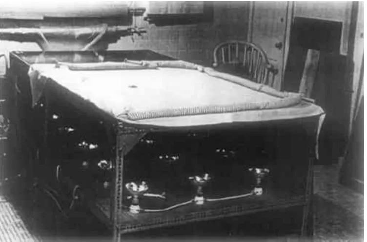
Fig. 1. Hot table, with heating lamps visible.
For the frame, one needs seven 12′ lengths of 2 1/4″ × 1 1/2″ perforated angle iron. This is then cut into the required lengths and bolted together to create a frame that stands 3′ high and has the outside measurements of 8′ × 4′. Further lengths of iron are bolted approximately two feet from the top, to act as re-enforcements for the legs and to create a ledge on which the shelf can rest. The four corner supports and also those midway down the long sides are further re-enforced with triangular gussets. Although, at this stage, the “table” will seem very insecure, it is best to leave the bolts slightly loose to allow for
adjustments, and the rather awkward manoeuvre of inserting the shelf. The angle iron and gussets should be obtainable from any reasonably large distributor of industrial supplies and hardware.2
The single most expensive part of this hot-table is the working surface, and it seems advisable to go for good quality. After considerable discussion with a local distributor of aluminum sheeting who has been extremely helpful, it was decided to use their second best quality, #6061, 96″ × 48″ × 1/4″, weighing about 115 lbs, and currently costing $265.3 This has an excellent surface and any small scratches caused by handling and cutting can be polished out with fine steel wool. The underneath surface must be sprayed with matte black paint to enhance absorbtion of heat, and it can be placed on the metal frame.
The aluminum sheet is not secured at the edges in any way, to allow for possible expansion, but the manufacturers say this is unlikely to be more than .015″.
The shelf consists of a 4′ × 8′ sheet of five-plywood, A/D quality.4 This is sawn in half to give two pieces of 4′ square, both of which are then painted with two coats of poly-urethane wood sealer, and placed, A side up, on the ledges provided by the angle iron frame. Each half is then marked out into nine squares of 16″ each, in the middle of which is screwed a porcelain lamp socket.
These are then wired together in parallel into four groups using Romex 12/2 (two groups with five lamps, and two with four). This enables one to use only half, or even three-quarters of the table if necessary (Fig. 2). With eighteen heat bulbs of 250 watts each, one is using 4500 watts; so given that the electricity supply is 120 volts, one needs a total of 37.5 amperes. Each group of lamps is plugged into a grounded (three hole) socket which is wired to a circuit breaker, with the thermostat let in between the socket and the breaker (Fig 3).
Fig. 3. Diagram of hot-table electrical system.
Those who are experienced electricians can probably assemble this
themselves, but for us lesser mortals it is wiser to employ the services of a professional.
The thermostat,5 set to close at 145° and open at 155°, can be taped
underneath the aluminum as a fail safe device. This will need a bit of adjusting to keep the temperature in the region of 150°, but with the use of eye, hand, table thermometers and experience, there seems little danger of over-heating (Fig. 4).
corners, on the near side of the table, and Everco brass pipe connectors screwed in from below, on to which transparent vinyl tubing is fitted. This tubing is then led to the vacuum pump, with an automobile vacuum cylinder (used for windshield wipers) and gauge let into it about ten to twelve inches from the table end. The actual vacuum is created by a 1/12 hp pump, wired for 115 volts, with a 4″ diameter diaphragm. Great difficulty was encountered in achieving control over the amount vacuum. An ordinary pressure regulator proved virtually useless; at around 10–12″ hg it suddenly collapses and one finds one's pressure galloping up to 20–22″ hg, with no control in between. Most regulators are designed for compression, not vacuum; the only actual vacuum regulator we were able to track down costs about $45. However, in order to control a vacuum one simply has to create a small leak of air
somewhere in the system, so the final solution is a needle valve6 with which one can control the vacuum pressure with amazing accuracy (Fig. 5).
Fig. 5. Diagram of hot-table vacuum system.
The membrane on the surface is made of two three-yard lengths of 36″ latex sheeting,7 .010″, held together with a suitable adhesive tape (such as
Fig. 6. Hot table in use, with heating lamps shielded.
1 CONCLUSION
THERE ARE PROBABLY several improvements or alterations that can be made on this basic design, depending on the preferences of each individual conservator. Certainly we would like to hear of a good source of latex, and although we rarely find any need for the thermostat, undoubtedly a more reliable method for securing it would be preferable. Some conservators might prefer to have the vacuum drawn through the membrane on the surface8 and also add exhaust fans around the sides to speed the cooling process.
theory, the exact distance from bulb to aluminum, for even heating could probably be worked out by a heating engineer.
To sum up, we think that this vacuum hot-table, apart from its cheapness, is an attractive proposition because of its safety, relative speed in cooling, and accessibility for repairs.
ACKNOWLEDGEMENTS
GRATEFUL THANKS TO: Robert Williams of Choate Rosemary Hall for his interest and expert advice throughout the whole project. George Buttrick, for his electrical know how. Marsha McCarthy, of Mohawk Aluminum for her interest and advice. Without their help, it is doubtful whether this table would ever have been built.
APPENDIX
1 APPENDIX
REFERENCES
“Heat Seal Lining of a Torn Painting with Beva” by Gustav A.Berger. Studies in Conservation, 20. 1975 pp 136
The angle iron and gussets were obtained from Church and Morse Inc., Meriden, Connecticut, 06450
Aluminum sheeting made by Kaiser Aluminum, Seattle, and distributed by Mohawk Aluminum, Wallingford, Conn., who say they will deliver to any part of the country.
A/D plywood has one surface that is good quality (A); the obverse side (D) may contain knots and other blemishes.
Pump (Speedaire #2Z627), Thermostat, (hot water control model #2E327) and Vacuum gauge are all made by Dayton Electrical Co., Chicago, and obtainable from any branch of W. W. Graingers.
Needle valve and Everco brass fittings are obtainable from wholesale distributors of automobile parts. Diameters are a matter of choice, but 1/4″−3/8″ seems a convenient size.
Latex supplied by Greene Rubber of Connecticut, 59 Old Broadway, North Haven, Conn.
JAIC 1980, Volume 20, Number 1, Article 4 (pp. 36 to 40)
DESIGN AND CONSTRUCTION OF A SUCTION TABLE
Roy L. Perkinson
ABSTRACT—A design for an inexpensive, easily disassembled and cleaned suction table of simple construction is presented, with a description of the materials used. The application of the table in paper conservation treatments is briefly described, and its use for textile conservation is suggested.
SINCE ITS INTRODUCTION by Marilyn Weidner in 19741 the suction table has generated considerable interest among paper conservators. It has become an important tool in solving a variety of problems previously thought difficult or impossible to treat. The table described here was contructed by the paper conservation laboratory at the Museum of Fine Arts in 1976 and has been in regular use since then. The design is only one of many possible variations, but it is hoped that the specific details of construction will be of interest to others who are considering building their own versions.
Three general guidelines were observed in the constuction of the table: it should not be extremely expensive; construction should be simple and should not require unusual or highly specialized tools; it should be possible to replace or clean the components easily. In this instance construction was simplified by the discovery of a used drafting table which was still in sound structural condition. It was the right size; its metal legs and supports, obviously of an early vintage, were old enough to be potentially attractive rather than merely functional; and its wheels insured that it would be possible to move the table without difficulty. An added bonus was the fact that both the height and angle of the table top were adjustable. The ability to place the table in a vertical format once the art is positioned is an important feature (Fig. 1). Accidental dripping of liquid onto a picture's surface while spraying is a real possibility with unpleasant results. Not only is this danger limited by upright positioning, but solvents can be applied more evenly using a vertical mode.
The original top of the table was removed and replaced with the suction table itself, shown in Figure 2 and diagrammed in Figure 3. A shallow plenum space was incorporated in the bottom of the table to promote efficient and uniform airflow over the entire surface. The holes in the upper layer of plywood are ½″ in diameter and are spaced at 4″ intervals. This distribution was arrived at more by intuition than calculation, and seems to have been quite successful. A layer of ¼″ hardware cloth2 was selected as a simple,
inexpensive means of facilitating air flow between the honeycomb3 and the plywood. Without this layer, air would be unable to pass through the
Fig. 1. Suction table, with top tilted toward the vertical and the underside visible.
Fig. 3. Suction table in cross-section. 1, honeycomb; 2, ¼″ hardware cloth (screen); 3, ¾″ exterior grade plywood; 4, plenum (air space); 5, ¾″ exterior grade plywood; 6, metal tubing
for attaching vacuum; 7, 1″ × 3″ wooden frame.
The wooden parts were put together with waterproof resorcinol glue and screws, and joints between the two plywood layers and the outside frame were rabbetted to make them more secure and airtight. After assembly, all wooden surfaces were sealed against moisture with two coats of polyurethane varnish. In addition, the joint between the outside frame and the bottom layer of plywood was sealed on the outside with silicone rubber caulking compound. The air inlet at the bottom consist simply of an “elbow” pipe from an
industrial vacuum cleaner held in place by a tight friction fit. A second layer of plywood, 6″ square, was added near the center of the bottom of the table at the point where the pipe was inserted, to give greater support and a more secure fit for the pipe (see Fig. 1). Placement of the suction inlet at the side is a possibility which might prove convenient for other table designs.
A birch veneer plywood cover was constructed to slip over the top of the table when not in use, providing both protection and an extra work surface. Finally, the metal supports and legs were painted bright red, a vast improvement over the previous battleship gray.
The overall size of our suction table is approximately 44″ × 60″. It is certainly not necessary to construct a table of this size. Dimensions of about 30″ × 40″ or even slightly smaller would probably be useful for many projects, yet I have found the large size of our table helpful on several occasions.
used by dentists (dental dam),5 polyethylene, or mylar. Although I have not encountered this problem, it is conceivable that too much suction coupled with the use of moisture could produce an impression of the honeycomb, evident as a slight irregularity, on the surface of the paper. To guard against this
possibility it is advisable to work at the table with excellent light falling at an oblique angle and to be alert at all times for the slightest hint of undesirable changes in the surface texture of the picture. The use of a fine mesh screen such as a polyester silk screen fabric beneath the blotting paper may also assist in maintaining the desired planarity. In an earlier version of the table, a valve was incorporated for the purpose of regulating suction. In practice it was found that regulation could be accomplished effectively and sensitively by simply folding over the desired amount of masking material near the outer edge of the table, allowing air to pass through and thus reducing suction.
To facilitate operation of the table an electrical switch was mounted on each of the two long sides, just beneath the edge of the table. These control a single electrical outlet beneath the table, into which the vacuum cleaner is plugged; therefore the suction can be turned on or off quickly and conveniently, without requiring the conservator to step away from the table.
One of the practical problems associated with the use of the table is that the vacuum cleaner is rather noisy. Although this is not too troublesome for short periods of operation, it may be objectionable if the table is in continuous use for a long time. In addition, if flammable solvents are used on the table, there is the theoretical possibility of ignition. The path of air through the vacuum cleaner is essentially independent of the air passing around the motor, but the design of the motor housing is such that air leaving the holding tank cannot be prevented from coming in contact with the motor. Therefore we explored two alternatives: using a different type of motor in a remote location, or
constructing a different housing for the motor. Since the planned renovation of our laboratory will permit the installation of an explosion-proof motor totally outside the work space, we are proceeding with the first alternative, and the table will then be attached to an exhaust tube within the laboratory. The second alternative could be accomplished, I believe, by purchasing a motor of the correct size and type, then constructing a soundproof container for it and attaching an exhaust tube to it which would conduct vapors to a safe distance away, or possibly directly into an existing fume exhaust system. The Lamb Electric two-stage by-pass vacuum motor might be satisfactory for this purpose.6 (I am grateful to Tim Vitale, Intermuseum Laboratory, for this suggestion.)
of blotting paper in place of a picture and leaving only a very small area uncovered by the masking material. If signs of a grayish deposit are produced on the blotting paper, steps should be taken to provide a cleaner environment for the table. One might also consider placing a thin blotter over the picture as an added precaution during drying/conditioning operations, which tend to require more time than other procedures. The top blotter will block particulate material from the surface of the art work.
Since the construction of our suction table, we have found it useful for a variety of problems such as reduction of stains from water or pressure sensitive tapes, conditioning/drying of moist paper to room humidity, and drying pictures that were executed in a medium that might easily offset during ordinary drying between blotters. We have also observed that the table may be helpful in other areas of conservation. Our textile conservator, Leslie Smith, has found it useful for certain procedures such as the removal of deposits of glue from textiles whose colors would otherwise be adversely affected by overall treatment with water.
REFERENCES
AIC Bulletin, vol. 14, no. 2, pp. 115–122.
Hardware cloth is a heavy, open-weave wire screen and is available at many hardware stores or lumber supply houses.
Honeycomb panels are available from Hexcel Corporation, P.O. Box 709, Bel Aire, Maryland 21014.
Pullman model JB-102 industrial vacuum cleaner. Pullman/Holt Products, Division of Purex Corp., 123 Medford Street, Malden, Mass. 02148. Clarke model 612 vacuum cleaner. Clarke-Gravely Corp., 2800 Estes Street, Muskegon, Mich. 49441.
JAIC 1983, Volume 22, Number 2, Article 4 (pp. 82 to 91)
LEAF CASTING ON THE SUCTION TABLE
Robert Futernick
ABSTRACT—Modification of the “leaf casting” technique for use on the vacuum suction table is described. A plastic container, placed above an area of missing paper, holds water and pulp until suction is applied from below. Fibers, pulled evenly into proper position, bond with the edge of the original sheet. Prints or drawings that exceed the size of the suction table may still be treated. Through localized wetting or the use of alcohol as the casting liquid, certain problems associated with water soluble media and standard casting procedure can be overcome.
THE BEST REPAIR of paper with losses or tears requires a technique that is appropriate to the particular qualities of a paper, including consideration of intended use of the item. For example, a hole in a book page could be filled with strong, flexible Japanese paper to accommodate handling. The same hole in a master drawing would have different repair requirements, since
minimizing the visual effect of damage would be of greater concern. The availability of a growing number of repair technologies enables the
conservator to meet the needs presented by particular problems. Some repair methods are as old as papermaking itself, while other techniques have evolved during the last 30 years. Modification of the “leaf casting” technique for use on the vacuum suction table offers a new refinement for repair and is the subject of this paper.
Historically, filling holes with similar paper has been the most frequently used repair method. It can work well, but success will depend on adequate time to do the task, a good selection of repair papers, a minimum of edge
discoloration, and the skill of the conservator. Problems can develop, however. Secure joining of the insert to the original may be difficult, especially with thick, brittle paper. Also, distortion of the original sheet can develop because of the different expansion characteristics of the two papers or the introduction of adhesive necessary for joining the insert.
Because of its strength and flexibility, Japanese paper has been widely used for book leaf repair. Two or more thin sheets laminated together and slightly overlapping the original can create an excellent fill. Though different in color and texture from many Western papers, Japanese paper inserts often provide a sympathetic match. This method seems to have less propensity for paper distortion than other techniques. Furthermore, the strain of attachment is spread over a larger area. This may be extremely important when the edge of the original sheet is weak or the intended use of the material involves
1 LEAF CASTING
IN THE LATE 1950s, Esther Alkalay and Ulia Petrovna Nyuksha began experimenting with the concept of filling missing areas in paper with fibers suspended in a liquid medium. By 1961, equipment for this purpose had been developed and was in use in laboratories located in Eastern Europe and the U.S.S.R. The process has come to be known as “leaf casting,” and is best described in the preprints of the 1980 Cambridge Conference (see
bibliography). Today the Library of Congress and the Northeast Document Conservation Center both use leaf casting machines based on Alkalay's design. Other models, varying in cost and sophistication, have been developed in recent years and are in use in laboratories throughout the world.
1.1 Steps of traditional leaf casting
1. The damaged paper should be thoroughly wet. (Extending the soak time and increasing the wetness of the sheet aids in later bonding.) 2. The paper is placed on a permeable surface at the bottom of the leaf
casting tub. A hold-down mechanism is usually employed to restrict movement of the damaged sheet when water is added to the area above the paper.
3. A precise amount of pulp of appropriate fiber type and color is stirred into the water bath. It is important that measurement of the missing area and paper thickness be accurate and the pulp addition be correct so that the cast fills will equal the thickness of the original paper. Simple graph paper or a planimeter can facilitate this calculation. 4. Suction, whether from an electric pump or gravity, is applied to the
space below the damaged work. Water in the top portion drains
through the voided spaces only, depositing an even layer of pulp across the loss.
1.2 Characteristics and Qualities of Leaf Casting
Leaf casting has distinct advantages over other methods of filling losses. If one's work is organized and equipment is properly adjusted, damage to paper can be repaired very quickly. It is possible to create a smooth, flexible and unobtrusive transition from the fill to the original paper. And if fibers of similar dimensional characteristics are selected and prepared, distortion can be minimized or avoided. However, there are areas of concern and potential problems in leaf casting, and they should be understood in order to take full advantage of this technique.
The bonding of the fill material to the old paper can be problematic. The quality of connection will depend on a) the state of deterioration of the
In the past, various kinds of adhesives have been added to the casting liquid to improve bonding. Unfortunately, adhesives affect the entire object during the period of immersion and drainage, not just the fill. This changes the nature of the paper—at the very least—and if the adhesive material proves to have poor aging characteristics, the entire artifact will suffer. Therefore, the addition of adhesives, though helpful in bonding, should be carefully considered and avoided when possible.
Conventional leaf casting requires the complete immersion of the paper in water. Clearly, many items cannot undergo this action without risking loss or alteration of the media. As a remedy, application of fixing agents has been suggested. However, it seems imprudent to impose such an altering measure just for the purpose of repair when other satisfactory methods are available. Hand pulp technique and localized leaf casting methods do not require total water immersion.
During leaf casting, there is some pulp deposition onto the surface of the original paper. As the fluid level in the tank gets low during the final stage of drainage, some of the fibers in the solution will become affixed to the surface of the original. This may be minimized if the pulp-in-fluid concentration is kept low, though in certain cases some cleanup may be necessary. (If the work is one-sided and the casting takes place with the work face down, then slight deposition on the verso may not be an issue.)
In an early publication too obscure to remember, reference is made to the employment of chronic gum chewers for major restoration ventures. Here, beating and fibrilation of fibers with cuspid and molar action is gentle but thorough, with chemical processing provided by enzymatic mechanisms (spit). Unfortunately, with leaf casting activity on the rise, it has become more and more difficult for conservators to locate eager chompers to fill increasing demand.
Many conservators have turned to the use of household blenders for conversion of old paper to pulp. Recently, blender preparation has been criticized in the literature in favor of beating devices especially designed for the purpose. Certainly, beating machines do provide precise control over fiber length and hydration and they will accommodate the use of raw fibers.
Petherbridge points out that bonding and dimensional stability is very dependent on pulp quality and preparation. However, the use of expensive equipment is not always practical or necessary. If care is shown in the selection of paper for repulping and the fiber-to-water ratio is properly
2 HAND PULP TECHNIQUE
HAND METHODS for filling losses with paper pulp have been in use around the world for a long time. Keiko Keyes outlined her technique at the AIC Conference in Dearborn in 1976. She demonstrated how a hand method, depending on the skill of the conservator, could be successfully used to repair damaged artwork quickly without requiring expensive equipment. Because the entire sheet does not require complete wetting, artifacts with media too
vulnerable for immersion casting can be safely treated with hand technique. Also, more control may be achieved with hand placement of fibers than with mechanical leaf casting. Damaged paper with small-to medium-sized holes are perfect candidates for this method, though larger losses in smooth regular papers are difficult to fill evenly by hand. A combination of hand and mechanical methods for use on a vacuum suction table provides a practical alternative to such problems.
3 VACUUM TABLE
WHEN MARILYN WEIDNER introduced the vacuum suction table at the 1974 AIC meeting, it was difficult to imagine all of its possible applications. Since that time, it has become such an important tool in most laboratories that paper conservators often wonder how they could practice without it. Many people have built, modified, analyzed and used suction tables over the last eight years. Inexpensive home-made models can serve quite well, as can the more expensive and elaborate commercially available models. Important factors to consider for both general use of the vacuum table and leaf casting are:
1. Openness of surface. Thick masonry tops tend to restrict air flow and become clogged.
2. Flatness of surface. Any material other than very fine screen or some perforated metals will impose their texture on the paper or blotter in contact with it.
3. Suction. The pump/fan arrangement should have the capability of lifting a column of water at least 80 inches high.
4. Air flow. This will vary depending on the size of the table. Generally 20 cubic feet per minute (CFM) per square foot of table surface is a reasonable guideline. A table 2′ × 3′ (6 × 20 CFM) would perform quite well for most purposes with a suction system that could deliver 120 CFM.
4 LEAF CASTING ON THE SUCTION TABLE
method remains the simplest and most direct approach for small holes, leaf casting on the suction table may be specially useful under certain conditions:
1. In the absence of a conventional leaf casting apparatus.
2. When the art object or document is larger than the dimensions of the leaf casting machine.
3. When the loss is large and requires a particularly even fill.
4. When the texture of the original sheet is an aesthetically important element and the repair calls for articulation of paper texture.
4.1 Advantages of suction table casting
1. The entire sheet does not always have to be wet before casting.
2. When water-sensitive media are present, another liquid such as alcohol may be utilized to carry the pulp into place.
3. Pulp deposition on the original paper is avoided, since very little liquid is used and only a small area of the original is exposed.
4. The quality of the join can be improved in cases where strength is important by casting half the fill and then turning the sheet over to complete the fill. This creates an actual encasement or overlapping of the edge on both sides. This variation is not only strong but offers the additional advantage of obscuring a dirty edge.
4.2 Modification of Suction Table for Leaf Casting
With only slight modification, many vacuum/suction table designs may be used for leaf casting. A major issue is the ability of the system to handle safely a gallon or more of water at one time. The liquid should be disposed of before it reaches the suction device. This can be accomplished in several ways:
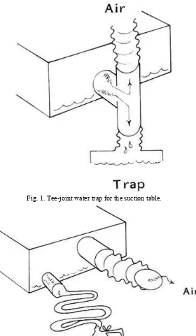
1. Installation of a tee in the tubing leading to the pump/fan. The pipe fitting should be placed so that liquid will fall into a trap for collection and future disposal (see figure 1). Plastic (PVC) tubing and fittings are especially useful for the plumbing. The pipe can be easily cut to size with a handsaw and simply slip-fitted for connection. Though joins can be welded with solvent for permanent high pressure usage, this is not recommended. It is an advantage to be able to undo a connection for later adjustment or alteration.
Fig. 1. Tee-joint water trap for the suction table.
Fig. 2. Plenum space used as a water trap and fitted with a drain.
4.3 The Process
Leaf casting on the suction table does not differ in principle from the
conventional method except that the casting fluid is contained only in the area directly above the loss. A discussion of the process follows:
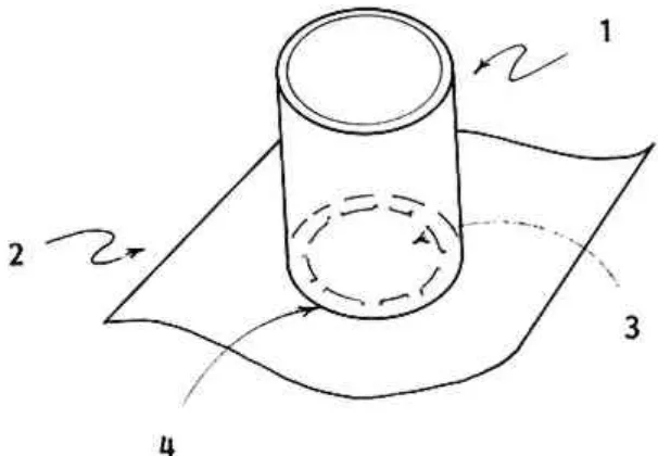
in various sizes (2″ to 6″ in diameter) and easily cut into 4″ lengths [1]. (Containers for larger losses are easily fashioned by heating and
bending plexiglas sheeting into a rectangular shape, slightly larger than the hole). Thin plastic film (.002″) is cut into a rectangular shape several inches larger than the diameter of the tubing [2]. Then a hole, larger than the loss but slightly smaller than the opening of the
container tube, is cut in the center of the rectangle [3]. Silicon adhesive applied to the bottom edge of the tube affixes the container to the plastic mask [4]. This pulp mold will seal itself when suction is applied without harmful downward pressure of the mold on the paper artifact. 2. Arrangement of materials on the suction table (see figure 4). A piece of
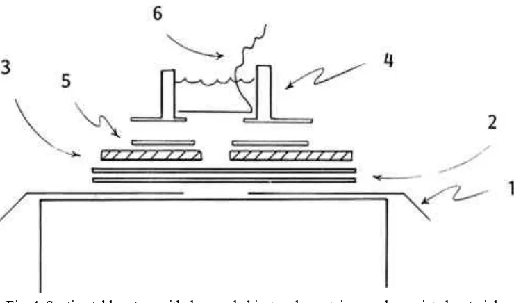
thin plastic film cut larger than the top of the suction table is placed on the surface so that the extending edges hang over the table [1]. A hole in this film is cut centrally, its dimension slightly larger than the opening of the container mask. Two layers of non-woven spunbonded polyester fabric (Reemay, number 2014 or 2114, from Dupont) are placed over the opening to provide a surface on which to cast [2]. Reemay, an especially suitable material, aids in creating very even pulp formation and imparts a texture much like that achieved by contact with papermaker's felts. The damaged original is set on the Reemay so that the loss is located over the opening in the table [3]. The container can be set directly on the surface of the paper [4]. However, the opening in the mask will not conform exactly to the contour of the loss. If precision in casting is required, pulp deposition in areas other than the hole can be avoided by cutting and properly placing a Reemay mask onto the paper [5]. This extra step can be done quickly and enables one to use just a few different-sized containers for most castings.
3. Delaying drainage. An interval of time is needed for filling the container with water and pulp. A removable plug can be fashioned using plastic film, cut so that it just fits in the container tube (see figure 4 [6]). A string or narrow strip of plastic affixed to one edge of the plug facilitates removal. The plug, inserted inside the container just prior to applying suction, is pulled tightly against the container mask forming a temporary bottom to the container when suction is activated. Lifting the attached string removes the plug, allowing the slurry to be pulled into the area of loss. Larger areas of loss are plugged better if several pieces of plastic film (each with a tail) are placed to overlap each other slightly. Multiple plug removal becomes a louvre action, thus avoiding tidal waves.
4. Selection and processing of pulp. The quality of a casting and its adhesion to the artifact is dependent on many factors: the type of fiber, the nature and duration of processing, and the method of casting and drying. Pulp selection and beating is a complicated issue. The
pulp derived from old, good quality papers beaten in a household blender. The use or addition of linters or commercially processed pulps can provide special advantages in terms of bonding strength and
textural quality.
5. Correct addition of pulp to casting liquid. Too much pulp yields a fat, irregular, uneven casting and too little will produce transparency and thinness. (As previously mentioned, it may be desirable in some cases to cast a thin fill from one side, turn the paper over, and complete the casting from the other side. This encases the edge of the original, providing more strength at the join, while perhaps hiding a dirty edge.) The achievement of a fill that has comparable thickness to the original as well as appropriate texture and opacity is a complicated matter, and practicing on holes in mock-ups is necessary to master this technique. However, it is helpful to have a starting point, and the following
indicates a method:5,6Cast, press, dry, and cut a rectangle of paper to a convenient size (e.g., 20cm × 25cm). Measure and record the thickness and weight of the sample (e.g., .0125cm thick and 4.0
grams).Determine volume-per-gram by multiplying the length of rectangle times the width times the thickness and divide by the weight of sample (e.g., 20cm × 25cm × .0125cm divided by 4 grams = 1.563 cm3/gram).Find the area of the loss and measure the thickness of the damaged artifact. Counting squares of graph paper or outlining the perimeter of the hole with a planimeter are two methods that have been used to approximate area. Either technique is adequate for occasional casting. However, if the volume of leaf casting activity is high, it may be worth speeding area calculation with the aid of a microcomputer. Simply tracing the outline of the loss with a “light pen” on a Graphics Tablet connected to an Apple Computer, for example, will yield a very quick and accurate area measurement.Determine the weight of pulp required for the casting by dividing the volume of the loss by the volume of a gram of pulp (e.g., area of loss 150cm22 × thickness of artifact .017cm divided by volume/gram 1.563cm33 = 1.63 grams).It is convenient to refrigerate pulp in solutions of known concentration (e.g., 1%) for storage. It is then easy to mix different colored pulps, test the resulting color by drying, and pour out the required amount (e.g., 1.63 grams is approximately equal to 163ml of a 1% solution). The addition of a small quantity of fungicide to the solution will prevent bacterial and mould growth.
6. With suction holding the container and plug in position, the pulp solution is poured into the container. Vacuum pressure is then adjusted. This is a matter of experience, but pressure influences flow and the flow rate will affect the casting. The tail of the plug is quickly pulled. This action opens the bottom of the container, enabling the liquid to drain.
to a hard-surfaced table. Rubbing over the fill with a bone burnisher while it is still wet serves to compact fibers and improve the join. Using plastic film or polyester fabric as an interleaf during burnishing will help to achieve a more sympathetic match of textural qualities. Subsequent drying of the sheet in open air is often preferable to pressing even under light weight. Remoistening for final pressing and flattening is accomplished with controlled, even water application. By this time, the joined areas are more secure and not as susceptible to splitting.Large castings have a tendency to detach at the join, a condition that is exacerbated when the artifact is particularly
expansive. Pressing or slowing the drying process may be necessary to maintain the integrity of the bond.Very tender attachments or those that will have to withstand the strain of handling, can be strengthened with application of Japanese tissue along the join or all over as a lining.3
8. If the addition of adhesives to the fill seems appropriate—for strength or as a sizing for later toning—then it might either be added to the casting solution or applied locally after the fill has undergone preliminary air drying.
9. In special cases, it is desirable to approximate the textural qualities of the original in the casting. Articulation of laid lines in the cast area can minimize the visibility of damage. This becomes important with a work of art on textured paper scheduled for exhibition in subdued and slightly raking light. The use of a laid screen, aligned on a light table to match the laid markings of the paper and placed just under the loss during the casting process, can impart a sympathetic texture to the fill. A method for creating an assortment of laid screens for this purpose is described as follows:Make a ruled line drawing using black ink on clear acetate. The width of the lines should be drawn to equal the space in between the lines. Lay out the grid so that approximately 24 black lines are set to the inch (see figure 5).Using a photostat machine, incrementally enlarge and reduce the line drawing to achieve a desired range of sizes.Place a line drawing in direct contact with a piece of photo-silk screen emulsion. The photo-sensitive emulsion is a
screen to the fumes generated by a formaldehyde bath and allow to dry. Then spray the screen with a material such as Scotchgard to protect the emulsion further.Repeat this process for each line drawing to create a catalog of various-sized screens that can be used again and again.It should be noted that this process is not for the creation of a perfect reproduction or a facsimile of a missing area. Instead, its use is intended to minimize the visibility of damage that would otherwise interfere with the aesthetic impact of a work of art.
10.Casting with alcohol. There are instances where even partial wetting of a paper artifact is not safe. Experiments have shown that an acceptable casting can still be accomplished, providing the paper or media are not adversely affected by alcohol. The pulp is prepared by first beating it in water in the usual manner. Most of the water used in beating is extracted by pouring the slurry through a strainer. The damp fibers are transferred back to the blender where a quantity of ethanol is added for a second beating. The paper artifact is wet with ethanol prior to
placement on the table and casting is performed as previously
described. The resulting fill will be quite soft and felt-like because not much bonding occurs. However, this may be remedied by localized application of water or water plus a sizing agent followed by burnishing and pressing.
Fig. 4. Suction table set up with damaged object, pulp container, and associated materials, ready for use.
Fig. 5. Suitable line spacing to make a laid-line pattern in casting.
5 ALTERATION OF THE VACUUM TABLE DESIGN
RECENTLY we constructed a small portable vacuum table that especially lends itself to leaf casting and pulp filling procedures. It is made entirely of clear plastic, so that when it is placed on a light table, light is transmitted up through the top of the suction box. Permeability of a small part of the upper surface was achieved by drilling many tiny holes in the Plexiglas. Marjorie Cohn suggested at the Milwaukee meeting that a fritted glass plate might be set in the top surface to allow transmission of light without the need for drilling. A full size transparent suction table would be most desirable.
Fig. 6. A light-transmitting suction table for pulp casting or treatment of a small area.
5.1 Working features of a transmitting suction table
1. A light suction table is extremely versatile. It can serve for leaf casting as just described, conventional pulp filling, and for very precise and selective addition and deposition of pulp.
2. For conventional pulp filling, suction is applied but temporarily
blocked by placement of a sheet of thin plastic film over the opening of the table. When proper pulp density and distribution is achieved, the “table cloth” (plastic film) is yanked and the liquid quickly falls, leaving the fibers in place.
3. For certain shaped holes or art that cannot tolerate much wetting, a transmitting table is extremely useful. A dirty edge or a small loss, tear or paper thinning is set on Reemay over the suction area with the vacuum on. Pulp, suspended in very dilute concentration, is dripped onto the damaged area with a wide-tipped medicine dropper. Air flow takes the pulp to the open area and causes adhesion to the edge of the top or to the previously dripped application. It is possible to build up multiple layers until the desired result is achieved without much lateral wetting. It is necessary to send distinct droplets. Attempting pulp application from close range will result in fiber clumping.
6 CONCLUSION
provide further refinement now available to the conservator.
ACKNOWLEDGEMENTS
THE SUCCESS of this project was dependent on the help and patience of all the people in our laboratory, namely Pauline Mohr, Patricia Morris, Linda Odgen, Sylvia Rodgers, and Janice Mae Schopfer. Special acknowledgement goes to Keiko Keyes. It was through several meetings with Keiko that the original concept was refined and simplified. Finally, this paper became much more readable after the careful attention of Jennifer Futernick.
REFERENCES
Alkalaj, Stella. “The Chemical Laboratory for Hygiene, Conservation and Restoration of Damaged Written Materials.” Restaurator1:2 (1969), pp.87–91. Wachter, Otto: “Methods of Restoring Old Prints, Documents and Drawings Using Liquid Paper Pulp,” I.I.C. Lisbon Conference 1972, Conservation of Paintings and the Graphics Arts (1972), pp. 971–974.
Alkalay, Esther Boyd. “The History and Development of Leaf Casting,” The Conservation of Library and Archive Materials and the Graphics Arts, Cambridge 1980 Preprints (1980), p. 187.
Petherbridge, Guy. “Analysis, Specification, and Calculation in the Preparation of Leaf Casting Pulp: A Methodology.” The Conservation of Library and Archive Material and the Graphic Arts, Cambridge 1980 Preprints (1980), pp. 189–209.
Keyes, Keiko Mizushima, and Farnsworth, Donald S. “Practical Application of Paper Pulp in the Conservation of Works of Art on Paper.” Preprints. Fourth annua