HUMBOLDT-UNIVERSITÄT ZU BERLIN INSTITUT FÜR INFORMATIK
COMPUTER ARCHITECTURE
Lecture 10
ALU
Sommersemester 2002
Leitung: Prof. Dr. Miroslaw Malek
ALU
ARITHMETIC / LOGIC UNIT
•
Arithmetic Units Classification
•
Number Representations
•
Hardware/Software Continuum and Vertical Migration
•
Integer Arithmetic
– addition/subtraction – multiplication/division
•
Decimal Arithmetic Unit
•
Floating-Point Arithmetic
– addition/subtraction – multiplication/division
TYPES OF ARITHMETIC UNITS
•
SERIAL
– Operations are performed bit by bit. A carry out bit is fed back in the next cycle. Results are routed to a shift register to assemble a word.
•
PARALLEL
– Operands are presented to the unit in parallel. To carry out the operation circuits may be:
• Sequenced (ripple carry technique)
• Occur concurrently, e.g., carry-lookahead technique
...
+
A
B
carry
Z
an 1−
bn 1− b0
a0
z0
zn 1−
...
...
...
A
an 1− a0
B
bn 1− b0
...
Z
z0
zn 1−
...
ALU
32 32
ARITHMETIC UNITS CLASSIFICATION
BY LEVEL OF DESIGN COMPLEXITY
1. Fixed-Point Arithmetic
– a. addition/subtraction of positive numbers
– b. addition/subtraction of positive and negative numbers – c. multiplication
– d. division
2. Decimal Arithmetic (BCD)
– similar to Fixed-Point arithmetic
3. Floating-Point Arithmetic
– a. multiplication – b. division
TRADEOFF BETWEEN
HARDWARE/SOFTWARE IMPLEMENTATION
•
ALU units usually as minimum have addition and subtraction, then:
– Multiplication (fixed) – Division (fixed)
– Floating Point
– Special Functions/Tables
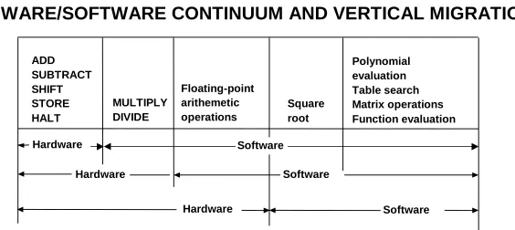
HARDWARE/SOFTWARE CONTINUUM AND VERTICAL MIGRATION
Software ADD
SUBTRACT SHIFT STORE HALT
MULTIPLY DIVIDE
Floating-point arithemetic operations
Square root
Polynomial evaluation Table search Matrix operations Function evaluation
Hardware
Hardware Software
NUMBER REPRESENTATION (1)
0 1 2 N-1 N-2(a) Circle representation of
integers mod N (b) Mod 16 system for
2's-complement numbers 0000 0001 0010 0011 0100 0101 0110 0111 1000 1001 1010 1011 1100 1101 1110 1111 0 +1 +2 +3 +4 +5 +6 +7 -8 -7 -6 -5 -4 -3 -2 -1
Bit pattern Values represented
---b3,b2,b1,b0 Sign and
magnitude 1's complement 2's complement
---0111 +7 +7 +7
0110 +6 +6 +6
0101 +5 +5 +5
0100 +4 +4 +4
0011 +3 +3 +3
0010 +2 +2 +2
0001 +1 +1 +1
0000 +0 +0 +0
1000 -0 -7 -8
1001 -1 -6 -7
1010 -2 -5 -6
1011 -3 -4 -5
1100 -4 -3 -4
1101 -5 -2 -3
1110 -6 -1 -2
1111 -7 -0 -1
---NUMBER REPRESENTATION (2) BCD
1. Binary-Coded Decimal (BCD) can represent the numbers 0 through 9 in 4 binary bits. Arithmetic is accomplished modulo 10. Since 4 bits = 24 = 16, numbers greater than 10 are adjusted by adding 6 (=0110), (16-10 = 6).
– 1010 is used for “+” and 1011 for “-”
• Example:
4739+1281=6020
in BCD-Code:0100
0111
0011
1001
+ 0001
0010
1000
0001
*( 0101
1001
1011
1010)
The number needs to be adjusted by adding 0110:
0101
1001
1011
1010
1
0110
0101
1001
1100
0000
1
0110
0101
1010
0010
0000
1
0110
0110
0000
0010
0000
NUMBER REPRESENTATION (3)
BINARY REPRESENTATION
1. Position and magnitude
–
B=b
n-1...b
1b
0–
V(B)= b
n-12
n-1+...+b
12
1+b
02
02. Signed numbers
b
n-1=0
positiveb
n-1=1
negativen - number of bits N - the actual number
– Sign & Magnitude
– 1's Complement N
N=(2
n-1) - N
negation
– 2's Complement N*
N*= 2n - N = (2n - 1) - N+1 = N + 1 negation plus one magnitude
b0 bn-1
FRACTIONAL 2's COMPLEMENT REPRESENTATION (I)
N* = 2
n+1- N
•
FRACTIONS FORM
X.XXX . . . X 0.-1-2 . . . . -m
•
FOR FRACTION
n=0
N*
=2
1- N
•
EXAMPLE
Let
N = 0.0100101
FRACTIONAL 2's COMPLEMENT REPRESENTATION (II)
decim. binary decim. binary
positive negative
0 0.000
.125 0.001 -.875 1.001 .250 0.010 -.750 1.010 .375 0.011 -.625 1.011 .500 0.100 -.500 1.100 .625 0.101 -.375 1.101 .750 0.110 -.250 1.110 .875 0.111 -.125 1.111
N
*
= 2 -N
2 = 10.000 .625 = 0.101 - (.375) = - .011 + (-.125) = 1.111 -.375 = 1.101 .500 =*0.100
.375 = 0.011 .375 = 0.011 = 0.011 + (.250) = 0.010 + (-.250) =-0.010 =1.110
ARITHMETIC OPERATIONS
1. Addition of positive numbers
2. Addition/subtraction of positive and negative numbers
3. Multiplication
EXECUTION TIME
Execution time =
∑
Logic Gate Delay- Assume any stage of an n-bit serial adder requires 5 ns - A 32-bit add takes 32 x 2 ns = 64 ns
- Memory access may be 5 ns (basic cycle)
- We want to improve the add speed to fall below the basic cycle speed:
- Faster logic
- Accelerating the carry
The carry causes delay, so the basic problem is to
N-bit adder/subtractor with
2's-complement ADD/SUBTRACT control
sn-1
2's-complement's big advantage: same circuit for add and sub
ADD
→
S = X + YSUB
→
S = X + Y +1yn-1 y1 y0
ADD = 0 SUB = 1
ADD/SUB control
cn
s1 s0 n-bit adder
LOGIC FOR ADDING TWO BITS
y i c i x
i c i x i y i
c i+1 x i
y i c i x i y i c i x i
y i c i x i cy ii
ADDER (A)
x i y i
c i+1
s i c
i
s i = x iyic i + xi yi c i + xi yici c i+1 = yi ci + xi yi
+ x y c i i i x c ii +
FAST ADDER DESIGN
The logic equations for two level logic expressions are: (1)
Factoring the second of these (carry-out equation) into (2)
and defining a generate function (3)
and a propagate function (4)
we can write (5) (6) i i i i i i i i i i i i
i
x
y
c
x
y
c
x
y
c
x
y
c
s
=
+
+
+
i i i i i i
i
x
c
y
c
x
y
c
+ 1=
+
+
i i i
i i
i
x
y
x
y
c
c
+1=
+
(
+
)
i i i
x
y
G
=
i i
i
x
y
P
=
+
i i i
i
G
P
c
c
+1=
+
1 1 1
1
1+ − − −
−
=
i+
i ii
G
P
c
c
1 1 1 − −
−
+
=
i i ii
G
P
c
c
)
(
1 1 11 − − −
+
=
i+
i i+
i ii
G
P
G
P
c
(7) (8)
1 1
1
1 − − −
+ = i + i i + i i i
i G P G P P c
c
0 0 0
1 2
1 1
1 G P G P P G P P G P P c
c i + = i + i i − + i i − i − + ... + i ... + i ...
Pure Carry Lookahead circuit for computing the carry out cn of an n-bit adder
ci
Gi-1 Pi-1 Gi-2 Pi-2 Gi-3 P1 G0 P0 c0
0 0 1
0 1 1
2 1
1 P G P P G P P c
G
0 0 1 2 3 0 1 2 3 1 2 3 2 3 3
4 G P G P P G P P P G P P P P c
c = + + + +
x3 y3 x2 y2 x1 y1 x0 y0
P1 G1 c4
s3 s2 s1 s0
c0
Control inputs
4-bit integrated ALU block Example: a 4-bit adder
K=0 1st Block K=1 2nd Block etc.
BLOCK LOOKAHEAD
K K P
G~ ,~
0 1 2
3P PP
P P~o =
0 1 2 3 1 2 3 2 3 3
0 G P G P P G P P PG
G~ = + + +
Carry for a 16-bit adder:
0 0 1 2 3 0 1 2 3 1 2 3 2 3 3
16 G P G P P G P P P G P P P P c
Ad a) A carry can be generated in three logic gate delays. 1 Compute Pi, Gi
1 AND P's, G's
1 OR resulting AND P's, G's 3
Ad b) The completion of the sum can be generated in three additional logic gate delays.
1 Form 1 AND
1 OR AND Products 3
TIMING FOR AN ADDITION OPERATION BASED ON
CARRY LOOKAHEAD
i c i i i i ii y c x y c
x , , , , ,
Two expressions must be evaluated a) Carry Lookahead
b) The Sum
i i i i i i i i i i i i
i x y c x y c x y c x y c
s = + + +
0 0 1 0 1 1 2 1
1 P G P P G P P c
G
LIMITATION
a) Carry Lookahead with 4 blocks (32 bit, k=8)
Gate fan-in is limited to 8 (usual circuit constraint)
7 delays at 5 ns per 1 gate
→
35 ns for an add Generate Gk Generate PkForm C31 Form S31 2
2 3
1
delays
Generate Pi
1 Generate Gi
Form C8 2
Form C16 2
Form C24 2
Form C31 2
Form S31 3
delays
b) Carry Lookahead fully integrated (32 bits, k=32)
without circuit constraints
CARRY SKIP ADDER
a0b0
c0 a3b3 ...
P4,7
c4
P8,11 c8
P12,15 c12 a15b15
CARRY SELECT ADDER
c0 a0b0
a1b1 a2b2
a3b3
s3 s2 s1 s0 0
a4b4 a5b5
a6b6 a7b7
1 a4b4
s7 s6 s5 s4
c4
- two additions are performed in parallel, one assuming carry 0 the other assuming carry 1
- when the carry is finally known, correct sum is selected
SUMMARY - ADDITION TECHNIQUES
Technique Time Space
Ripple O(n) O(n)
CLA (Carry Lookahead) O(log n) O(n log n)
Carry skip O(n)
Carry select O(n)
Serial addition
simple logic
↔
slow execution Parallel additioncomplex logic
↔
faster execution - Ripple carry- Carry lookahead - Carry skip
- Carry select
) n ( O