A UNIFIED BLENDING FRAMEWORK FOR PANORAMA COMPLETION VIA GRAPH
CUTS
Kai Chena, Jian Yaoa,∗, Menghan Xiaa, Xinyuan Guib, Xiaohu Lua, Li Lia
a
School of Remote Sensing and Information Engineering, Wuhan University, Wuhan, Hubei, P.R. China bSchool of Geodesy and Geomatics, Wuhan University, Wuhan, Hubei, P.R. China
[email protected] -http://cvrs.whu.edu.cn/
Commission III, WG III/3
KEY WORDS:Image Completion, Panorama, Graph Cuts, Luminance Compensation, Image Blending, Feathering
ABSTRACT:
In this paper, we propose a unified framework for efficiently completing streetview and indoor360◦panoramas due to the lack of bottom areas caused by the occlusion of the acquisition platform. To greatly reduce the severe distortion at the bottom of the panorama, we first reproject it onto the ground perspective plane containing the whole occluded region to be completed. Then, we formulate the image completion problem in an improved graph cuts optimization framework based on the statistics of similar patches by strengthening the boundary constraints. To further eliminate image luminance differences and color deviations and conceal geometrical parallax among the optimally selected patches for completion, we creatively apply a multi-bland image blending algorithm for perfect image mosaicking from the completed patches and the originally reprojected image. Finally, we back-project the completed and blended ground perspective image into the cylindrical-projection panorama followed by a simple feathering to further reduce artifacts in the panorama. Experimental results on some representative non-panoramic images and streetview and indoor panoramas demonstrate the efficiency and robustness of the proposed method even in some challenging cases.
1. INTRODUCTION
A panorama is an image with a wide angle of view, which has been widely used for street view photos and indoor virtual tour recently. A panorama with a view angle of360◦ is common in specific applications. To obtain such 360◦ high-resolution panoramas, one common way is to capture multiple images syn-chronously from an integrated platform with multiple cameras whose viewpoints cover the whole360◦ except for the ground region occluded by the platform itself and then mosaic these im-ages into a complete360◦panorama. This way has been widely used in industry, for example, Google Street View, and Chinese Baidu and Tencent Street View, by mounting such an integrated platform on a mobile vehicle or a backpack. Another simple and popular way is to capture multiple images at different times with a single camera mounted on a static platform (e.g., a tripod) by rotation and then generate a panorama from these images. This way is widely applied for panorama acquisition in indoor scenes or relatively small spaces. All of these acquisition ways cannot perfectly cover the complete360◦viewpoint due to the ground occlusion caused by the platforms themselves. To quickly obtain a perfect and complete360◦ panorama, the image completion and blending techniques can be applied to complete the ground occluded region. In addition, for some privacy protection, we can also apply image completion to conceal the sensitive image regions.
Image completion aims to generate visually plausible completion results for missing or content-concealed image regions. In gen-eral, most of image completion algorithms are divided into two categories: diffusion-based and exemplar-based. Earlier work-s (Ballework-ster et al., 2001, Roth and Black, 2005, Levin et al., 2003, Bertalmio et al., 2000, Bertalmio et al., 2003) typically used the
∗Corresponding author
diffusion-based methods, which find the suitable colors in the re-gions to be completed through solving partial differential equa-tions. These methods usually make use of the consistency of an image and are only suitable for filling narrow or small holes in the image. The ground bottom region to be completed in a360◦ panorama is usually too huge to be effectively completed with these diffusion-based methods.
matched similar patches in the image and found that the statis-tics of these offsets are sparsely distributed. Referring to dom-inant offsets as labels to be optimized, (He and Sun, 2014) de-fined a MRF energy function, which was optimized via graph cuts (Boykov et al., 2001). The final image completion was im-plemented with the guidance of the optimized label map. In gen-eral, these exemplar-based methods are able to be more suitable for filling huge holes in images, in which the image structural information plays an important role.
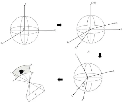
Although the state-of-the-art image completion algorithms can generate satisfactory completion results in most cases, the ground bottom area in a360◦panorama to be completed is usually large with severe distortion, which makes existing image completion algorithms very challenging or even impossible for completing it. In this paper, we propose a novel unified blending framework for image completion, especially completing panoramas with a view angle of360◦. The whole framework is comprised of five main steps as shown in Figure 1. Firstly, we reproject the cylindric-projection360◦panorama onto the ground perspective plane con-taining the whole occluded region to be completed, which greatly reduces the distortion and makes the exemplar-based image com-pletion methods feasible. Secondly, inspired by the method pro-posed by (He and Sun, 2014), we formulate the image comple-tion problem in an improved graph cuts optimizacomple-tion framework based on the statistics of similar patches by strengthening the boundary constraints in the smooth and data energy terms. Third-ly, to further eliminate image luminance differences and color de-viations and conceal geometrical parallax among the optimally s-elected patches for completion, we propose to first apply the glob-al luminance compensation followed by applying a multi-bland image blending algorithm for perfect image mosaicking from the completed patches and the originally reprojected image. Fourth-ly, we back-project the completed and blended ground bottom im-age into the cylindrical-projection panorama. Finally, to further reduce artifacts and keep the good resolution in the panorama, we propose to apply an image feathering on the original panora-ma and the back-projected one.
The remainder of this paper is organized as follows. The whole unified panorama completion framework will be detailed intro-duced in Section 2. Experimental results on some representative non-panoramic images and streetview and indoor panoramas are presented in Section 3 followed by the conclusions drawn in Sec-tion 4.
2. OUR APPROACH
Our proposed unified blending framework for panorama com-pletion will be introduced in the following five subsections. In Section 2.1, we first introduce a theoretical foundation that we can reproject a360◦panorama onto the ground perspective plane containing the whole occluded region. Inspired by the method proposed by (He and Sun, 2014), the proposed image completion method under an improved graph cuts optimization framework will be presented in Section 2.2. To generate perfect completion results, we first perform a global luminance compensation opera-tion on all the optimally selected patches for completing and the original background image and then apply a multi-bland image blending on all luminance corrected patches and the originally reprojected image, which can greatly eliminate image luminance differences and color deviations, and conceal geometrical paral-lax among the optimally selected patches. These two operations are introduced in Section 2.3. The back-projection is the reverse process of panorama perspective projection and they share the same theoretical foundation. The completed and blended image
Figure 3. An illustration of two rotation processes to get a per-spective projected image from a cylindrical-projection panorama. Along the arrow: original sphere coordinate systemS−X1Y1Z1, rotatingϕabout theY1axis to getS−X2Y2Z2, rotatingωabout theX2axis to getS−X3Y3Z3, and final projection process.
is back-projected to the cylindrical-projection panorama, which is introduced in Section 2.4. Finally, to further reduce artifacts and keep the good resolution in the panorama, we propose to apply an image feathering on the original panorama and the back-projected one, which is introduced in Section 2.5.
2.1 Panorama Perspective Projection
To reproject a360◦panorama onto the ground perspective plane, the main work is to find a transformation from a pixel on the cylindrical-projection panorama to the corresponding pixel on the perspective projection image. We introduce a virtual sphere co-ordinate system as a transition of this problem. As shown in Fig-ure 2, a pixelAon a360◦panorama has a simple correspondence with the pixelA′. These two corresponding pointsAandA′are linked by two longitude and latitude angles(θ1, θ2). The pointA′ also has three-dimensional coordinates(XS, YS, ZS)in this
vir-tual sphere coordinate system. From the virvir-tual sphere to the re-projected perspective image, it needs getting through two rotation processes with two rotation angles(ϕ, ω) and one perspective transformation as shown in Figure 3. The specific rotation angles (ϕ, ω)denote the sight direction looking at the occluded bottom region of a panorama. If we denote the three-dimensional per-spective coordinates(XP, YP, ZP), according to the principles
of rotation transformation, the perspective transformation can be formulated as:
for two rotation matrices with the rotation anglesϕandω, re-spectively. When reprojecting the panorama onto the ground per-spective plane, apart from the sight direction, the field of view and the focal length should also be specified properly to obtain a projected image in a suitable size to contain the whole occluded bottom region.
2.2 Image Completion via Graph Cuts
state-of-Figure 1. The flowchart of the proposed unified blending framework for panorama completion.
Figure 2. The perspective projection transformation from a cylindrical-projection panorama to a virtual sphere.
the-art image completion algorithms and achieves great perfor-mances in filling huge holes in images. Similarly, we formulate the image completion problem in such a graph cuts optimization framework based on the statistics of similar patches but with two improvements strengthening the boundary constraints.
(He and Sun, 2014) first matched patches in the known region of the image using a Propagation-Assisted KD-Trees (He and Sun, 2012). Then, they calculated dominant offsets based on these matched patches. These dominant offsets present the self-similarities of the image, which are referred as a set of labels to be optimized in graph cuts. After that, they defined a Markov random field (MRF) energy function as follows:
E(L) =X
x∈Ω
Ed(L(x)) + X
(x,x′)|x∈Ω,x′∈Ω
Es(L(x), L(x′)), (2)
whereΩstands for the unknown region to be completed,x de-notes a point inΩ,(x,x′)denotes a pair of four-connected neigh-bouring points, andLrefers to the label map, which assigns each unknown pixelx ∈ Ωa labelL(x). Each label corresponds to one of the pre-selected dominant offsets. If a labeliis assigned to the pixelx, i.e.,L(x) = i, it means that the color ofxwill be completed by that of the pixel atx+oiwhereoidenotes the offset coordinates of the labeli.
In (He and Sun, 2014), the data energy termEd in Eq. (2) is
defined as:
Ed(L(x)) = (
0, if the labelL(x)is valid forx, +∞, if the labelL(x)is invalid forx. (3)
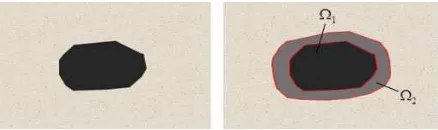
Figure 4. An illustration of an unknown region to be completed with a dilation operation: (Left) the original missing part; (Right) the dilated result.
And the smooth energy termEsis defined as:
Es(L(x),L(x′)) =kI(x+o(L(x)))−I(x+o(L(x′)))k2+
kI(x′+o(L(x)))−I(x′+o(L(x′)))k2, (4)
whereI(·)denotes the color values of a pixel in the imageI, and o(·)denotes the offset coordinates of some label.
Ω3. The data energy term is modified as follow:
whereDS is used to measure the difference of Ω3 before and
after optimization and imposes important boundary constraints. Here, we consider both color intensities and gradient magnitudes inDS, which is defined as:
DS=kI(x+o(L(x)))−I(x)k2+
k∇I(x+o(L(x)))− ∇I(x)k2
where∇Istands for the gradient map of the imageI.
For the smooth energy term, only color intensities are considered in (He and Sun, 2014). When the image of the scene is com-plex enough, it may find a pixel that has a similar color but is not suitable for the missing pixel anymore. As we know, gradient contains more information about image structure. So, we com-bine it with color intensities to construct our smooth energy to reduce the artifact, which is defined as:
ES(L(x), L(x′)) =EcolorS +α×ESgradient, (6)
whereαis a weight parameter to balance color intensity and gra-dient terms (α= 2was used in this paper),
With both improved data and smooth energy terms, the total en-ergy function can be optimized in a graph cuts enen-ergy optimiza-tion framework with a publicly available multi-label graph-cuts library1. The optimized output is a label mapL, which assigns each unknown pixel with an offset label.
2.3 Image Blending
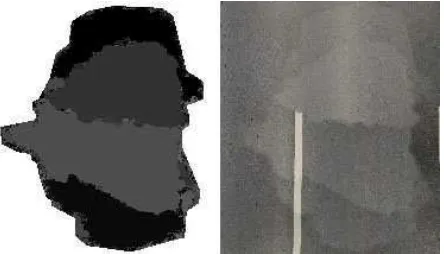
Different labels guide the pixels in the unknown region to be com-pleted to find the optimally corresponding one at different parts of an image. Different patches generated by the optimal label map maybe result in luminance differences, color deviations, and even geometrical parallax among the finally completed image re-gion, as shown in Figure 5. To greatly alleviate these issues, we choose to apply a multi-bland image blending algorithm (Burt and Adelson, 1983) for perfect image mosaicking from the com-pleted patches and the originally reprojected image.
To make use of the multi-bland image blending algorithm, we first generate the label mask map for each single label. Then, we expand these label mask maps with a dilation operation to make them having overlaps, which is the basic requirement of using this blending algorithm. For each expanded label mask map, we indi-vidually generate its corresponding image according to the patch offset the label refers to. Figure 6 presents three selected label mask maps with their corresponding sub-images. Especially, we refer to the whole background mask, which is not required to be
1Available at http://www.csd.uwo.ca/faculty/olga/
Figure 5. An illustration of the optimal label map (Left) and its correspondingly completed image region at the bottom of a streetview panorama.
Figure 6. The mask maps corresponding to three labels in the top row and the corresponding sub-images in the bottom row.
completed, as another label and the background of the uncomplet-ed projectuncomplet-ed image as a sub-image, as shown in the last column in Figure 6. In this way, we not only blend sub-images generated by different labels and but also blend them with the background to suppress the seams between completed patches and the original background image.
However, while the luminance differences between neighboring patches or one between completed patches and the original back-ground image are very apparent, only applying a multi-bland im-age blending is not enough to eliminate the artifacts. In these extreme cases, we choose a simple gain model as the luminance refinement model to correct those patches used for completion before performing the multi-bland image blending. As for each pair of adjacent sub-imagesPiandPj, as illustrated in the
bot-tom row in Figure 6, we transfer them to thelαβcolor space, in which thelchannel denotes the main luminance component. The difference betweenPiandPjafter the adjustment can be written as:
eij= (aiµ(Pi)−ajµ(Pj))2+α((ai−1)2+ (aj−1)2), (9)
whereµ(·)denotes the mean luminance of valid pixels in some sub-image,αis a fixed weight for preserving the average variance of the images after adjustment. andaiandajstand for the gain
coefficients ofPiandPj, respectively. Considering the joint ad-justment for all the pairs of adjacent sub-images in allNlabels, the total difference can be written as:
E=Xi=1...N,j=1...N PiandPjare adjacent
eij. (10)
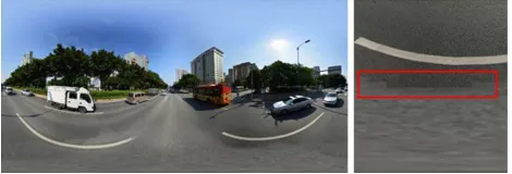
Figure 7. An illustration of obvious artifacts in a completed panorama by just back-projecting the completed image region in the ground perspective plane.
overlaps. It can be achieved by solving Eq. (10) through the linear least square algorithm.
Combining the luminance adjustment under a gain model and a multi-bland image blending algorithm can improve the luminance consistency of the completed projected image, even when the lu-minance difference is very large at the beginning, and generate a perfectly completed image as seamless as possible.
2.4 Back-Projection to Panorama
After mosaicking the completed image region, we back-project it onto the original panorama model to fill the occluded region at the bottom of the panorama. In Section 2.1, we have described the transformation from the cylindrical-projection panorama to the perspective projected image. Back-projection is its reverse process. By invertingRϕandRω, the transformation of back-projection can be formulated as:
When we back-project the whole mosaicked image region onto the panorama, the resolution has declined in the area that would be covered when the whole projected image is back-projected onto the panorama. Thus, we would just back-project the com-pleted image region corresponding to the missing one rather than projecting the whole mosaicked image. However, just back-projecting the completed image region would cause an obvious artifacts in the finally completed panorama due to different reso-lutions between the back-projected image region and the original panorama. In addition, it also introduces another issue. Although the blending result on the projected image is perfect, it changes the luminance and color of the image regions close to the com-pleted region but not inside it due to that the multi-band blending adjusts the whole image in the whole. As shown in Figure 7, if we only back-project the completed image region to the panorama, there exist obvious artifacts in the finally completed panorama.
The above mentioned two issues can be efficiently solved by ap-plying a simple feathering on the original panorama and the com-pletely back-projected one. As shown in Figure 8, we do feath-ering by adjusting the color intensities between linesAand B where the lineAdenotes the boundary of the occluded region to be completed and the lineBis far away fromAwith a fixed range. Given a pixelx between the linesA andB, the color intensities after feathering are calculated as follows:
Ip(x) =α×Iop(x) + (1−α)×Ibp(x), (12)
whereIp,Iop, andIbp stand for the feathered panorama, the o-riginal one, and the back-projected one completely from the mo-saicked image in the ground perspective plane, respectively, and
the feathering coefficientαis calculated as:
α=d(x, A)/(d(x, A) +d(x, B)),
whered(x, A)andd(x, B)represent the vertical distances from the pixelxto the linesAandB, respectively.
3. EXPERIMENTAL RESULTS
To sufficiently evaluate our proposed unified blending framework for panorama completion, we tested our algorithm on a set of representative streetview and indoor360◦ panoramas, provided by Baidu and Tencent.
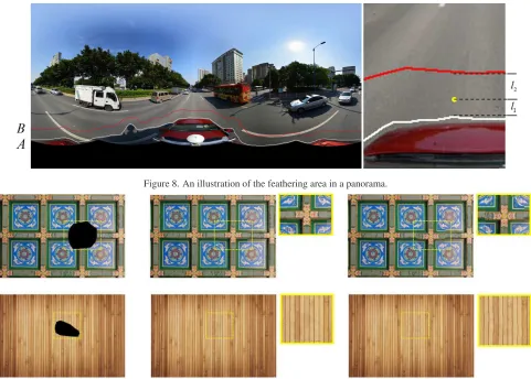
Recently, (He and Sun, 2014) proposed a graph-cuts-based image completion algorithm which is considered as one state-of-the-art method. However, their proposed method only considers color intensities in the definition of MRF energy function and its con-straints upon boundary areas are too weak to obtain some satis-factory results in some cases. To prove that our improvements do work well even in challenging cases, we tested it on some repre-sentative non-panoramic images. Figure 9 shows the completion results on two images with obvious self-similarities but with s-light deviations to some extent. From Figure 9, we observed that the completion results generated via our improved graph cuts is better than the original method proposed by (He and Sun, 2014). The misplacement between the whole completed image region and the boundary one of the original background image was ob-viously reduced as shown in the first row in Figure 9. Also, the misplacement between different patches inside the completed im-age region was alleviated to some extent as shown in the second row in Figure 9. This improvement benefits from strengthening the boundary and gradient constraints in our improved graph cuts optimization framework.
Figure 10 shows the comparative results with a multi-band blend-ing operation and without it applied in the ground perspective im-ages of the bottom regions of three streetview panoramas, from which we observed that the proposed blending strategy greatly eliminates the image luminance and color deviations, and also conceals small misplacements. The used luminance gain mod-el calculated the gain coefficients through the linear least square algorithm and adjusted the luminance of all the patches (i.e., sub-images) according to their own gain coefficients. Figure 11 shows comparative results, from which we observed that our used lumi-nance compensation strategy is able to correct all the completed patches and the original background image into a more consistent luminance. In some extreme cases with severe luminance differ-ences, directly applying the multi-band image blending would not work very well. In this condition, we first performed the lumi-nance compensation, whose advantage is illustrated in Figure 12. From Figure 12, we observed that the combined strategy slight-ly improves the blending result than just appslight-lying the multi-band blending.
Panorama feathering is a post-processing work to suppress the ar-tifacts on the completed panoramas. Figure 13 shows the compar-ative results on three streetview panoramas before and after feath-ering. From Figure 13, we observed that our proposed panorama feathering strategy can obviously eliminate the artifacts in the fi-nally completed panoramas.
Figure 8. An illustration of the feathering area in a panorama.
Figure 9. Comparisons between our improved graph cuts optimization and the original method proposed by (He and Sun, 2014): input images with black mask regions to be completed, the completion results by our method and the original one, from left to right.
Figure 12. Comparative results of performing image blending without luminance compensation in the top-right corner and com-bining two methods in the bottom-right corner
4. CONCLUSION
In this paper, we propose a unified framework for efficiently com-pleting streetview and indoor360◦panoramas due to the lack of bottom areas caused by the occlusion of the acquisition platform. The whole unified framework is comprised of five main stages. Firstly we reprojected the panorama onto the ground perspec-tive plane containing the whole occluded region to be completed. Secondly, the image completion problem was solved by formulat-ing it in an improved graph cuts optimization framework. Thirdly, we proposed to apply the luminance compensation and a multi-bland blending operations to greatly eliminate the luminance
d-ifferences of different patches used for completion, which has great effect in completing streetview and indoor360◦panoramas with complex lighting conditions. Fourthly, we back-projected the completed and mosaicked ground perspective image into the cylindrical-projection panorama. Finally, we did feathering on the completed panorama to further reduce artifacts in the panora-ma. This proposed unified framework is helpful to quickly com-plete a perfect and comcom-pleted360◦panorama. Experimental re-sults on a large amount of representative non-panoramic images and panoramas demonstrate the efficiency and robustness of our proposed panorama completion algorithm. Although the satisfac-tory results can be achieved in most cases, the current framework is not very feasible for the ground projection images with severe perspective distortion or with very cluttered backgrounds, which will be further studied in the future. In addition, we implemented the current completion optimization strategy with a single CPU, which can be further improved with multiple CPU cores and even multiple GPU ones.
ACKNOWLEDGMENT
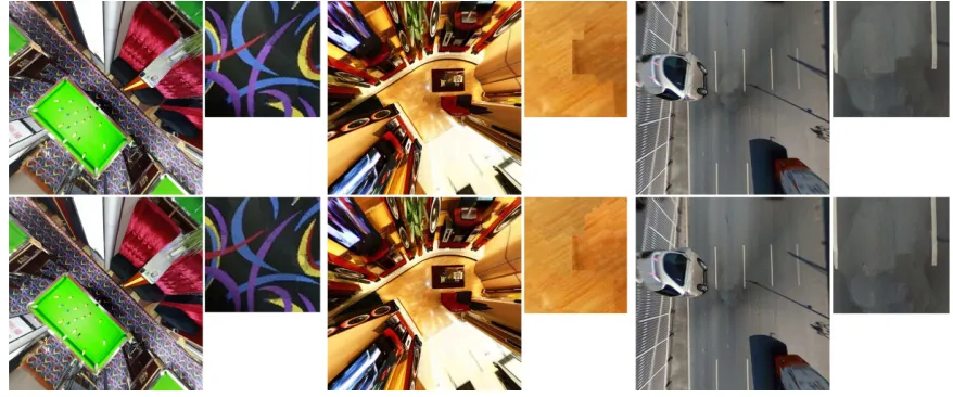
Figure 10. Comparative image completion results without applying a multi-band blending operation in the top row and with applying it in the bottom row.
Figure 11. Comparative results without the luminance compensation in the top row and with it in the bottom row.
REFERENCES
Ballester, C., Bertalmio, M., Caselles, V., Sapiro, G. and Verdera, J., 2001. Filling-in by joint interpolation of vector fields and gray levels.IEEE Transactions on Image Processing10(8), pp. 1200– 1211.
Bertalmio, M., Sapiro, G., Caselles, V. and Ballester, C., 2000. Image inpainting. In:Proceedings of the 27th annual conference on Computer graphics and interactive techniques, pp. 417–424.
Bertalmio, M., Vese, L., Sapiro, G. and Osher, S., 2003. Simulta-neous structure and texture image inpainting.IEEE Transactions on Image Processing12(8), pp. 882–889.
Boykov, Y., Veksler, O. and R.Zabih, 2001. Efficient approximate energy minimization via graph cuts. IEEE Transactions on Pat-tern Analysis and Machine Intelligence20(12), pp. 1222–1239.
Burt, P. and Adelson, E. H., 1983. A multiresolution spline with application to image mosaics. ACM Transactions on Graphics
2(4), pp. 217–236.
Criminisi, A., Perez, P. and Toyama, K., 2003. Object removal by exemplar-based inpainting. In:IEEE Computer Society Con-ference on Computer Vision and Pattern Recognition (CVPR).
Drori, I., Cohen-Or, D. and Yeshurun, H., 2003. Fragment-based image completion. In: ACM Transactions on Graphics (TOG), Vol. 22number 3, pp. 303–312.
Efros, A., Leung, T. K. et al., 1999. Texture synthesis by non-parametric sampling. In: IEEE International Conference on Computer Vision (ICCV), Vol. 2, pp. 1033–1038.
He, K. and Sun, J., 2012. Computing nearest-neighbor fields via propagation-assisted kd-trees. In:IEEE Conference on Computer Vision and Pattern Recognition (CVPR), pp. 111–118.
He, K. and Sun, J., 2014. Image completion approaches using the statistics of similar patches. IEEE Transactions on Pattern Analysis and Machine Intelligence36(12), pp. 2423–2435.
Jia, J. and Tang, C.-K., 2003. Image repairing: Robust image synthesis by adaptive nd tensor voting. In: IEEE Computer So-ciety Conference on Computer Vision and Pattern Recognition (CVPR), Vol. 1, pp. I–643.
Jia, J. and Tang, C.-K., 2004. Inference of segmented color and texture description by tensor voting. IEEE Transactions on Pat-tern Analysis and Machine Intelligence26(6), pp. 771–786.
Levin, A., Zomet, A. and Weiss, Y., 2003. Learning how to in-paint from global image statistics. In: IEEE International Con-ference on Computer Vision (ICCV), pp. 305–312.
(a)
(b)
(c)
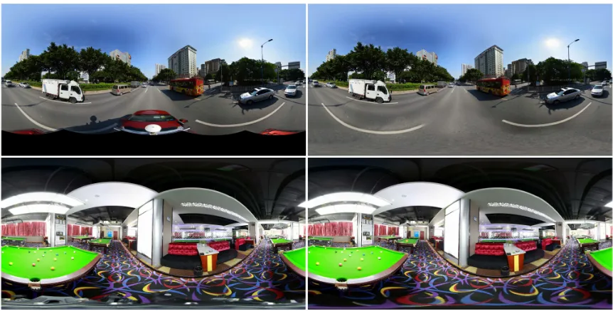
Figure 13. Comparisons of three completed streetview panoramas before feathering (top images) and after feathering (bottom images).
Figure 14. Two finally completed panoramas by our proposed unified framework.