MAPPING CROP STATUS FROM AN UNMANNED AERIAL VEHICLE FOR
PRECISION AGRICULTURE APPLICATIONS
T. Guo *, T. Kujirai, T. Watanabe
Hitachi, Ltd., Central Research Laboratory, 1-280, Higashi-koigakubo, Kokubunji-shi, Tokyo, 185-8601 Japan
[email protected]
IAG, TC I
KEY WORDS: Agriculture, Mapping, Mosaic, Spectral, Satellite, Image
ABSTRACT:
Remote sensing system mounted on unmanned aerial vehicle (UAV) could provide a complementary means to the conventional satellite and aerial remote sensing solutions especially for the applications of precision agriculture. UAV remote sensing offers a great flexibility to quickly acquire field data in sufficient spatial and spectral resolution at low cost. However a major problem of UAV is the high instability due to the low-end equipments and difficult environment situation, and this leads to image sensor being mostly operated under a highly uncertain configuration. Thus UAV images exhibit considerable derivation in spatial orientation, large geometric and spectral distortion, and low signal-to-noise ratio (SNR). To achieve the objectives of agricultural mapping from UAV, we apply a micro-helicopter UAV with a multiple spectral camera mounted and develop a framework to process UAV images. A very important processing is to generate mosaic image which can be aligned with maps for later GIS integration. With appropriate geometric calibration applied, we first decompose a homography of consecutive image pairs into a rotational component and a simple perspective component, and apply a linear interpolation to the angle of the rotational component, followed by a linear matrix interpolation operator to the perspective component, and this results in an equivalent transformation but ensures a smooth evolution between two images. Lastly to demonstrate the potential of UAV images to precision agriculture application, we perform spectral processing to derive vegetation indices (VIs) maps of crop, and also show the comparison with satellite imagery. Through this paper, we demonstrate that it is highly feasible to generate quantitative mapping products such as crop stress maps from UAV images, and suggest that UAV remote sensing is very valuable for the applications of precision agriculture.
* Corresponding author.
1. INTRODUCTION
Retrieval of spatial and spectral variability within crop field is of great importance for identifying crop stress that is one of the major factors influencing farming management decisions making. Satellite imagery has been widely utilized to address this problem due to its capacity to provide large spatial and temporal scales. But there are some basic limitations in this perspective. The first is the lack of timely imagery during the critical time of crop actively growing season when cloudy weather makes rare chance of image acquisition window existing. The second is the difficulties to reach a favourable trade-off among spatial and spectral resolution and data cost. We consider the low-cost remote sensing system mounted on unmanned aerial vehicle (UAV) could provide a complementary means to the conventional satellite and aerial remote sensing solutions especially for the applications of precision agriculture. UAV remote sensing offers a great flexibility to quickly acquire field data in sufficient spatial and spectral resolution at low cost. However a major problem of UAV is the high instability due to the low-end equipments and difficult environment conditions, and this leads to image sensor being mostly operated with a highly uncertain configuration. Thus UAV images exhibit considerable derivation in spatial orientation, large geometric and spectral distortion, and low signal-to-noise ratio (SNR). Accordingly it still remains a challenge to generate quantitative mapping products by means of a UAV remote sensing platform.
In the framework of UAV image processing, a very important task is to generate mosaic image which can be aligned with maps for later GIS integration. Image mosaicing is a very common method to generate large field of view (FOV) by aligning image sequences or video frames (thereinafter both as images) onto a predetermined reference plane (thereinafter as mosaic plane). It has popular applications in production of image map from aerial photos (Mosaics: Aligning Perspectives, 2001), and as well in creation of panorama from pictures taken by a normal digital camera.
In sequence, images are transformed to mosaic plane via a planar projective transformation so called homography. Typically the correspondence in the image and in the mosaic plane, and similarity measures along with spatial relationships among the corresponding features are used to estimate homography. Accordingly mosaicing consists of the steps: feature detection; feature matching; transformation model estimation; and image transformation and composition (Zitova and Flusser).
It is possible to spatially calibrate image through recovering the attitude of platform and geometrical relations of sensor model, and correspondence between image and terrain can be established with knowing digital terrain model (DTM). Image can be directly projected on the mosaic plane. Although commercial remote sensing and aerial photogrammetric systems work with this type of image calibration and provide very
accurate sensor parameters e.g. (yaw, pitch, roll and x, y, z), yet full self-calibration can not be achieved due to the complexities of system and terrain (Mikhail etc.). Additional ground controls are mostly required to implement highly accurate calibration. Instead of direct projection, the common method to estimate homography is implemented through analysis of corresponding image features in projected image and reference image. Lots of methods for feature detection and matching have been developed in last decades, e.g. Lucas-Kanade (Lucas and Kanade) is a very popular method for tracking optical flow features and RANSAC is normally applied to reject outliers of correspondences. Once the homography is calculated, each image can be registered to the previous image in the sequence, and aligned to mosaic plane through the previous images one by one.
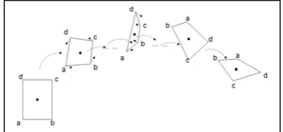
However it is in fact almost impossible to accurately align complete set of images because all images are inherently inaccurate, having displacement, distortion, motion parallax and moving objects, etc. All of this contributes to mosaicing errors and causes mosaic strip to offset from its real course and appears a curled strip when registration errors accumulate, as illustrated in figure 1. Therefore mosaic strip possibly goes any direction.
Figure 1. Mosaicing image appears a curled strip due to accumulation errors
In order to alleviate the mosaicing curling effect, it is necessary to adjust the image transformation parameters -- homography by using additional control information. Conventional methods fall into two categories according to their applications. One is bundle adjustment which is well developed in photogrammetry to minimize the image projection errors by a global optimization conducted jointly to all images and their ground truth. Bundle adjustment can achieve a high accuracy but requires considerable numbers of Ground Control Points (GCP) which impose intensive labour on its acquisition, yet it is the primary method in remote sensing industry for producing highly accurate mapping and survey products. On the other hand, efforts have been seen to reduce the requirements on GCP using camera parameters and image features, and plus proper tradeoffs between automation and accuracy makes these methods common in visualization, simulation, surveillance etc. non-measurement oriented applications.
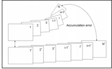
The existing methods for correcting curled mosaic strip directly adopt linear minimization of deviations and interpolate the accumulated error into each image in sequence, and result in an adjustment in transformation along the shortest path between the curled and real mosaic strips, such as the bundle adjustment and. These methods work well only without rotation or with small rotation presence. But if the mosaic strip curls very much
with a big turning angle, as illustrated in figure 2, the existing methods will fail to average accumulation error and intermediate images will appear to be flipped, and collapsed onto a line or even a point at a certain case.
Figure 2. Direct interpolation cases intermediate images to be flipped, and collapsed onto a line or even a point when a large
rotation presents.
In this paper, we focus on generating mosaics using images acquired from a small helicopter UAV with a multiple spectral camera mounted. We develop a framework to process UAV images, which mainly consists of geometric and spectral modules. Regarding geometric processing, after appropriate geometric calibration applied, we first decomposes a homography of consecutive image pairs into a rotational component and a simple perspective component, and applies a linear interpolation to the angle of the rotational component, followed by a linear matrix interpolation operator to the perspective component, and this results in an equivalent transformation but ensure a smooth evolution between two images. By suppressing the angular transformation on the mosaic plane, the drastic changes of intermediate image frame shapes, such as flipping affect can be effectively avoided, and a coarsely aligned mosaic strip is generated. Provided an image map is available, a fine adjustment is further done by applying mutual information to match the coarse mosaic with the image map so as to generate geo-referenced mosaics. To demonstrate the potential of UAV images to precision agriculture application, we perform the spectral analysis to derive some vegetation indices (VIs) maps of crop, such as normalized difference vegetation index (NDVI) etc. Meanwhile the corresponding VIs are also derived from both high resolution satellite images. A comparison shows that they are very suitable for deriving crop growth status, and suggest that UAV remote sensing is very valuable for the applications of precision agriculture.
2. METHODS
2.1 Image Registration
Given two images of the same scene taken from different viewpoints, in order to register the second image (projected image) with the first image (reference image), a homography needs to be figured out. A homography is represented as a 3x3 8-DOF 2D projective transformation matrix in this paper. Therefore at least four corresponding points are required for solving a homography. We adopt Harris corner detector (Harris and Stephens) to detect salient feature points in both images. Harris corner detector is a popular image processing tool, and it calculates 2x2 gradient co-variation matrix M over a predefined neighborhood, then it evaluates the determinant and trace of M for every pixel in destination image, and corners or other
interest points in general can be found as local maxima in the image.
Using the detected feature points in the first image, we apply a pyramid Lucas-Kanade method (Lucas and Kanade) to detect the corresponding feature points in the second image as illustrated in figure 3. Lucas-Kanade method is very effective to estimate optical flow or motion for two successive images, and it approximates the image signal using local Taylor series to derive the spatial and temporal derivatives between image sequences so that the corresponding feature point can be located. Lucas-Kanade method is usually carried out in a coarse-to-fine iterative manner, in such a way that the spatial derivatives are first computed at a coarse scale in a pyramid, one of the images is warped by the computed deformation, and iterative updates are then computed at successively finer scales.
Figure 3. Corners in the first image are detected using Harris corner detector, and then Lucas-Kanade optical flow is applied
to find corresponding feature points in the second image. Left image shows detected corners and optical flow vectors against
the detected corners on the right image.
The corresponding feature points detected cannot be guaranteed to be perfectly correct, since so many factors would lead to errors e.g. mis-matching. In order to estimate the homography, it is necessary to exclude the errors from the set of correspondence. We use RANSAC algorithm (Fischler and Bolles) to estimate homography from detected corresponding feature points. RANSAC is very robust for estimating parameters of a mathematical model from a set of observed data which contains outliers, which are data points that do not fit the model. In addition to this, the data points can be subject to noise. RANSAC starts with a random and small set of inliers to estimate the parameters of a model, then tests all of other data points whether the derived model fits the most of data points, if it does then globally optimize the parameters of model by removing outliers and including inliers only. RANSAC can achieve a high degree of accuracy when outliers are present in the data set, and the homography estimated in our scheme are generally satisfied.
2.2 Image Transformation
We estimate homography from the set of corresponding feature points, and it means that we implicitly uses a global mapping models to transform the second image to the first image, the transformation parameters will be applied to entire image. However it should be noted that image may be tessellated into patches and triangulation can be applied to transform each patch and to achieve a local mapping model. In fact, in a fine scheme of mosaicing, a global transformation is normally used to align image frame and a local transformation is carried out to stitch the seams of mosaic strip. We only discuss the global transformation in the followings and local transformation is beyond of the scope of this paper.
We use a pin-hole camera model and suppose the optical axis of camera is perpendicular to the flat scene, and the perspective
projection is defined as (1). It can map a general quadrangle onto a square while preserving straight lines and is determined by four independent control points.
(1)
(1)
2.3 Curled Mosaic Strip Correction
As discussed above, mosaic strip goes possibly any directions due to the uncertainty of image mosaicing. Generated mosaics normally cannot be directly referred to or overlaid with other geo-referenced data, such as maps. It becomes a quite annoying problem in visualization applications, such as environmental monitoring, surveillance etc. Generally geographical correction is operationally favourable to the practical applications. Applying GCPs to the mosaic strip can result in geo-referencing in some certain degree, but pixels in original images have been suppressed, merged, or discarded during image transformation process when generating mosaics, and it would greatly degrade the quality of image if simply wrap mosaic strip to GCPs. The mosaics produced in this way are very poor in either information content or image quality. The feasible way for geo-referencing should be implemented during image transformation of mosaicing, rather than after composition of mosaic strip.
Supplying a numbers of GCPs and integrating them within a global optimization process for estimating homography is the idea of the conventional bundle adjustment method, but it requires expensive, tedious and exhausting efforts for acquiring GCPs. We reduce the requirements for GCPs to a minimum level in the present method which only uses the given control information in the first and last images, that is four control points for each of the first and the last image, totally eight GCPs are required in minimum against hundreds of GCPs in conventional ways. With these given eight control points, the two ends of mosaic strip can be fixed at their “should-be” positions, then we can calculate the offset between the last image of curled mosaic strip and its should-be position, and this offset means the total amount of accumulation error, as illustrated in figure 4. Hence if we can derive some kinds of adjustment components to spread the accumulation error evenly over mosaic strip, then we can actually correct the curling effect of mosaic strip in some degree and further to generate much better visually pleased and generally-correct geo-referenced mosaic.
Figure 4. Mosaic strip can be fixed at its “should-be” position with the given control information in the first and last image, and the accumulation error can be derived as the offset of the
last image of curled strip and its ground truth.
)
The problem of curling effect correction becomes interpolation of accumulation error. As illustrated in figure 4, the accumulation error can be derived from the two transformation matrices which transform the last image to the mosaic strip and the ground truth respectively. Here we have:
M_last = M1*M2*…Mi*…Mn (2) M_last’= Homography( GCP1, GCP2, GCP3, GCP4) (3) where M_last is the homography which transforms the last image to mosaic strip, and Mi is the homography which transforms image i to image i-1; and M_last’is the homography which transforms the last image to the ground truth, and it is derived from the given four GCPs.
And the usual linear interpolation model is given by, [(1-t) * A] + (t * B), 0<=t<=1 (4) Direct interpolation of two status results in a transformation evolving from one end to another along the shortest path and it will flip intermediate images if a large rotation presents for a 3D perspective transformation as illustrated in Fig.1-2. And also (4) cannot be directly applied to matrices. Alexa provides a method for generating arbitrary linear combinations of matrices, and we adopt Alexa method to solve matrices interpolation. Two operators and developed in Alexa method are implemented using the matrix logarithm and exponential as following,
(5)
(6)
The operator implements scalar multiplication of a transformation matrix, and the operator is similar to matrix multiplication, with the exception that is commutative. For linear interpolation of matrices, rewrite (4) based on (5) and (6) as,
(7)
Replace matrix A and B with (2) and (3), we have our curled strip correction model,
(8)
We can generate adjustment matrices by directly applying (8) in most cases, but unfortunately Alexa method might be unstable as addressed in (Hawkins and Grimm). The matrix square root fails to converge for many transformations with rotational component >= 90 degree combined with a non-uniform scale. Therefore we first decompose the transformation into a rotational component and a perspective transformation component instead of directly applying (8), and then apply (4) to the rotational component and apply Alexa method only to the above perspective transformation component to ensure it always works within a stable and safe range.
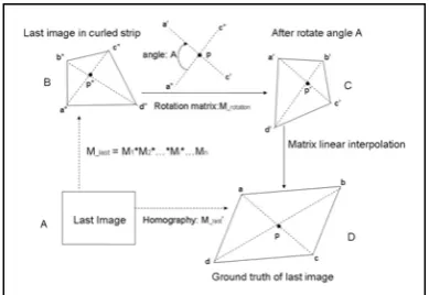
As illustrated in figure 5, the last image (status A) is transformed to an image (status B) in mosaic strip via the matrix M_last, meanwhile its ground truth (status D) is determined via the homography M_last’derived from the given ground control points. The “difference” between status B and status D in both position and shape indicates the accumulation error. As discussed above, we need to make a transformation scheme to evolve status B to status D smoothly so as to alleviate accumulation error fairly into image segments. We first rotate status B an angle to get status C, Which has generally similar orientation as status D, then apply Alexa method to linearly interpolate status C to status D. In this manner, the rotational component will be always very small from status C to status D, and it ensures Alexa method to work safely.
Figure 5. Image orientation is determined as the angle between one of the diagonals of image frame and one of axes regarding the intersection point of two diagonals as the origin. B is rotated to C, and C has generally similar orientation as D. Matrix linear interpolation is performed to evolve C to D, rather than from B
to D directly.
Since we suppose the optical axis of camera is perpendicular to the flat scene, and the principle point (PP) of perspective project is corresponding to the centre of image frame, therefore the intersection of two diagonals is approximately as the principle point. And because perspective project preserves straight lines, for an image after a perspective projection, the intersection of two diagonals of image frame is always corresponding to the principle point. In figure 5, we notate the diagonal ac, a’c’, and a”c” as primary diagonals, and bd, b’d’ and b”d” as secondary diagonals. The orientation of image is referred as the angle between the primary diagonal and x-axis in the document, but it could be an angle between any diagonal and any axis and a conversion necessary is required for the consistency. Once the orientation of image is determined, the rotation angle can be simply calculated via the difference of their orientations.
Hence, to transform status B to status D, we have the following steps:
1. Rotate status B an angle A with pp as the origin to get status C,
(9) and from (9)
(10)
A s
e
A
s
logB A
e
B
A
log log)
(
]
)
1
[(
t
A
t
B
t
[
0
,
1
]
)
'
(
]
)
1
[(
t
M
_last
t
M
_lasttemp last rotation
last M M
M_ _ * _ _
last rotation
temp
last M M
M_ _ _ 1* _
where
is the rotation matrix with rotation angle A.
2. Apply Alexa’s matrix linear interpolation operator to transform status C to status D,
(11)
Therefore, suppose the matrix M_i transform image i to the mosaic strip,
(12) where Mi is the homography which transforms image i to image i-1. Then the adjustment component consists of,
Rotational component,
(13)
Perspective component,
(14)
from (13) and (14), we have the adjustment component as, (15)
from (12) and (15), image i is finally transformed via
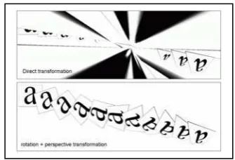
(16) As illustrated in figure 6, direct transformation seeks the shortest transformation path to reach the end, it flip the intermediate images for 3D transformation, meanwhile decomposing the transformation into rotational and perspective components will confine the transform on the mosaic plane and will not cause drastic change in shape of image frame, and it results in a smooth linear interpolation for transformation. By applying adjusted transformation matrix (16), every image is transformed to a certain amount in rotational and perspective components for compensating the accumulation errors, so that the curling effect is reasonably alleviated to achieve a much better visually pleased and generally correctly geo-referenced mosaic.
Figure 6. Direct transformation will flip intermediate images if a large rotation presents, meanwhile decomposing the transformation into rotational and perspective components will confine the transformation on the mosaic plane and results in a
smooth interpolation.
3. RESULTS AND CONCLUSION
As discussed above, the mosaicing errors are transited and accumulated to the last image. The key point of the solution for correcting curled strip is to derive a smooth interpolation scheme between the two status of last image, which indicate the accumulation error. figure 7, 8, 9 show the comparison of the present method which decomposes the transformation into rotational and perspective components against the conventional direct transformation methods.
Figure 7. Direct transformation method and the present method produce the same intermediate images while there is little
rotation presence between the two ends of status.
Figure 8. Direct transformation method changes drastically the shapes of intermediate images if there is a rotation angle present,
while the present method generates a smooth interpolation
Figure 8. When the rotation is large, direct transformation method will flip intermediate images, meanwhile decomposing
the transformation into rotational and perspective components will confine the transformation on the mosaic plane, therefore
generates smooth interpolation.
_perspectivei lasttemp M last
N
Figure 9. A comparison of curled mosaic strip correction. Left image is the mosaic generated based on image features only. Right image shows curling effect has been alleviated, control
information are applied to fix two ends of strip, and accumulation errors are spread evenly over the strip.
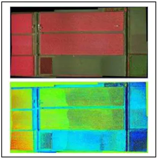
Figure 10. Generated UAV mosaic image of a crop field. The upper image is in false colour and the lower image is generated NDVI
Figure 11. A comparison of satellite image and UAV mosaic image of a crop field. Left image a pansahrpen Worldview-2 (©Digital Globe), right image is NDVI from a UAV mosaic.
In this paper, we have proposed a method to alleviate image mosaicing curling effect. Instead of direct interpolation, our method decomposes a transformation into a rotational component and a perspective component, and applies a normal linear interpolation to the angle of the rotational component, followed by a linear matrix interpolation operator to the perspective component. Our method enables a feasible transformation to ensure a smooth evolvement between two ends of status, therefore avoid drastically changing to the shape of intermediate image frames, and this provides a solution to interpolate accumulation errors of mosaicing into the even segments which are later applied to adjust the mosaic strip to generate generally correct geo-referenced mosaics. And we also demonstrate that UAV remote sensing is a very complementary means to satellite remote sensing. And we develop a framework to process UAV images in context of geometric and spectral processing. Further we show that it is highly feasible to generate quantitative mapping products such as crop stress maps from UAV images, and suggest that UAV remote sensing is very valuable for the applications of precision agriculture. References
Alexa M., 2002. Linear Combination of Transformations, in Proceedings of the 29th annual conference on Computer graphics and interactive techniques, San Antonio, Texas.
Chen H-M, Varshney p. k. and Arora M.K., 2003. Performance of Mutual Information Similarity Measure for Registration of Multitemporal Remote Sensing Images. In IEEE Transactions on geoscience and remote sensing, vol.41, No.11.
Fischler M. and Bolles R.C., 1981. Random Sample Consensus: A Paradigm for Model Fitting with Applications to Image Analysis and Automated Cartography, in Comm. ACM, 24(6). Harris C.J. and Stephens M., 1988. A Combined Corner and Edge Detector, in Proceeding of 4th Alvey Vision Conference, pp.147-151.
Hawkins A. and Grimm C. M., 2005. Animation: keyframing Using Linear Interpolation of Matrices, in ACM SIGGRAPH’05, July 2005.
Lucas, B., and Kanade, T. 1981. An Iterative Image Registration Technique with an Application to Stereo Vision, in Proc. of 7th International Joint Conference on Artificial Intelligence (IJCAI), pp. 674-679.
Mikhail E.M., Bethel J.S. and McGlone J. C., 2001. Introduction to Modern Photogrammetry. John Wiley & Sons, Inc.
Mosaics: Aligning Perspectives, 2001. GISCafe.com December 2001. http://www.integralgis.com/pdf/mosaic.pdf
Shmuel Peleg, Benny Rousso, Alex Rav-Acha and Assaf Zomet, 2000. Mosaicing on Adaptive Manifolds, in IEEE Transcations on Pattern Analysis and Machine Intelligence, Col.22, No.10.
Szeliski R. Video Mosaics for Virtual Environments. 1996. In IEEE Computer Graphics and Applications. March 1996.
Zitova B. and Flusser J., 2003. Image Registration Methods: A Survey, in Image and Vision Computing, (21) 977-1000.