ISSN: 1693-6930
accredited by DGHE (DIKTI), Decree No: 51/Dikti/Kep/2010 217
Maximum Output Power Tracking of Wind Turbine
Using Intelligent Control
Muldi Yuhendri*1,2, Mochamad Ashari2, Mauridhi Hery Purnomo2
1
Departement of Electrical Engineering, Universitas Negeri Padang (UNP) Jln. Dr. Hamka, Air Tawar, Padang 25132, Indonesia, Ph/Fax:+62751-445998/7055644
2
Departement of Electrical Engineering, Institut Teknologi Sepuluh Nopember (ITS) Campus ITS Keputih, Surabaya 60111, Indonesia, Ph/Fax:+6231-5947302/5931237
e-mail: [email protected]*, [email protected], [email protected]
Abstrak
Daya output turbin angin ditentukan oleh kecepatan angin. Daya output turbin angin dapat diatur dengan mengendalikan kecepatan generator dan sudut pitch turbin angin. Ketika kecepatan angin di bawah rating turbin, daya output generator dapat maksimum dengan mengendalikan kecepatan generator pada titik koefisien daya maksimum. Ketika kecepatan angin di atas rating turbin, daya output turbin akan melebihi rating daya generator. Dalam kondisi ini, daya output turbin perlu diregulasi agar sesuai dengan rating daya generator. Daya output turbin dapat diregulasi dengan mengatur sudut pitch turbin. Dalam paper ini dikembangkan strategi kontrol berbasis kendali cerdas untuk mengendalikan kecepatan generator dan sudut pitch turbin, sehingga daya output maksimum (MOPT) turbin angin dapat diperoleh pada setiap variasi kecepatan angin. Kecepatan generator dikendalikan dengan PI-fuzzy logic controller (PI-FLC) berbasis direct field oriented control (DFOC). Sudut pitch turbin dikendalikan dengan recurrent Elman neural network (RENN). Hasil simulasi dengan simulink Matlab menunjukkan bahwa aplikasi kedua pengendali ini sukses meregulasi daya output ketika kecepatan angin di atas rating turbin dan daya output generator dapat maksimum ketika kecepatan angin di bawah rating turbin.
Kata kunci: MOPT, turbin angin, PI-FLC, RENN, DFOC
Abstract
The Output power of wind turbine is determined by wind speed. The Output power can be adjusted by controlling the generator speed and pitch angle of wind turbine. When the wind speed below the wind turbine rated, the output power of generator can be maximized by controlling the generator speed at point of maximum power coefficient. When the wind speed above the wind turbine rated, output power of wind turbine will exceed the power generators rated. In this condition, the output power of wind turbine needs to be regulated to conform to the generator power rate. Output power of wind turbine can be regulated by adjusting the pitch angle of wind turbine. In this paper is developed the control strategies based intelligent control for controlling the generator speed and pitch angle of wind turbine, so the maximum output power tracking (MOPT) of wind turbine can be obtained at any wind speed variations. Generator speed is controlled using PI Fuzzy Logic Controller (PI-FLC) based Direct Field Oriented Control (DFOC). Pitch angle of wind turbine is controlled using Elman Recurrent Neural Network (RENN). The simulation results with Matlab Simulink shows that the both controller was successfully regulates the output power when the wind speed above the wind turbine rated and the output power can be maximum when the wind speed below the wind turbine rated.
Keywords: MOPT, wind turbine, PI-FLC, RENN, DFOC
1. Introduction
turbine. Variable speed wind generation system based on vector control has been developed in [1-9]. Vector control based on intelligent control has been developed in [10-14]. In [1-14], the wind turbine is operated with pitch angle fixed. It causes the wind turbine can not be operated on a second region. For wind turbine operation in the second region, has developed a variable speed wind turbine with pitch angle-regulated [15-17]. Several control strategies have been applied, among others, robust digital control [15], inteligent control based on RBFNN [16], and improved Elma Neural Network based Modified Particle Swarm Optimization [17].
In this paper, a MOPT strategy of WECS is developed to both operation regions, so the wind turbine can be operated for above the wind speed rated. The Maximum output power is obtained by adjusting the generator speed and pitch angle of wind turbines. Generator speed is controlled using PI-FLC based on DFOC method. Pitch angle of wind turbine is controlled using RENN. Control strategy is shown in Figure 1. In zone 1, the wind speed is lower than the wind speed rated (v1 ≤ v ≤ v2), while in zone 2 the wind speed above the wind speed rated of wind
turbine (v2 ≤ v ≤ v3). For zone 1, the generator speed
ω
m is controlled at maximum powercoefficient Cp_max with pitch angle
β
constan, such that the maximum output power can beobtained at each wind speed variations. For zone 2, the generator speed
ω
m was maintainedconstant and pitch angle
β
is controlled to lower the power coefficient, so that the output power of wind turbine in accordance with the rating of maximum power the generator.p
C
m
P
0 v1 v2
m
ω
_ max
p C
: constant
β
β
: variable
_ max_
m rat
P
v
(m/ sec) 3
v
Figure 1. Control strategy of wind turbine
2. Research Method
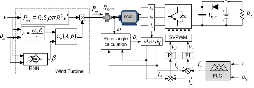
Model of WECS is shown in Figure 2. The model consists of horizontal wind turbine, squirrel cage induction generator (SCIG), voltage source converter, DC supply, resistor load and controllers. Converter is modulated by space vector pulse width modulation (SVPWM).
2 3
0.5
wt
P
=
ρπ
R v
( )
,p C λ β
mR
v ω λ =
m
ω
v
β
m
P
DC
V
− +
/ abc dq
− +
*
q
i
*
d
i
qi
d
i
q
v
dv
+
−
R
Lr
ω
eθ
r
ω gear η
v
DC supply is used for initial operation and supplying the generator when the WECS in the cut-in condition. For generator excitation, the capacitor mounted on the DC side of the converter. Model details are described in the following sections.
2.1. Squirrel Cage Induction Generator (SCIG)
In DFOC method, SCIG is modeled in dq axis. General equation of SCIG voltages in dq axis are described as [19-20]:
0
0
0
0
qs s s m qs
ds s s m ds
qr m r m r r r r qr
dr r m m r r r r dr
R
pL
pL
R
pL
pL
pL
L
R
pL
L
L
pL
L
R
pL
v
i
v
i
v
i
v
i
ω
ω
ω
ω
+
+
=
−
+
−
+
(1)
where
v
dqs andv
dqrare stator and rotor voltages in dq axis, respectively.i
dqs andi
dqr are statorand rotor currents in dq axis, respectively.
R
s andR
rare stator and rotor resitance,L
sandL
rarestator and rotor leakage inductance, respectively. Torque and power of SCIG are given by [19] :
(
)
1.5
e ds ds qs qs
P
=
v i
+
v i
(2)m m m
P
=
T
ω
(3)e m m m
T
= −
T
J
ω
&
−
D
ω
(4)where
P
e, P
m andT
m are output power of SCIG, Mechanical power of wind turbine andmechanical torque of wind turbine, respectively.
J, D
andT
e are moment inertia, damping ofwind turbine and electromagnetic torque of SCIG, respectively.
2.2. Wind Turbine
Wind turbine model is developed based on mechanical power equation of wind turbine. Mechanical power of wind turbine
P
m can be written as [18]:(
)
2 30.5 ,
m p
P
=
πρ
Cλ β
Rv
(5)where
ρ
,
λ
andR
are air density, Tip speed ratio (TSR) and blade radius of wind turbine, respectively. Power coefficient is determined by TSR and the pitch angle of wind turbine. The relationship of power coefficient, TSR and pitch angle of wind turbineC
p(λ
,
β)
can be expressedas [18] :
5 2
1 3 4 6
( , )
c i
p
i
C λ β
c
c
c
βc
e
λc
λλ
−
=
− −
+
(6)3
1 1 0, 035
0, 08 1
i
λ = λ+ β β− + (7)
where
c
1-c
6 are constants value of wind turbine. TSR is ratio of the angular velocity of windturbine with wind speed, which is formulated by [10]:
m
R
v
λ =
ω
(8)wind turbine varies on each change of wind speed and has a maximum point at the particular generator speed [18]. Maximum mechanical power
P
m_max is obtained at the point of maximum power coefficientC
p_max, as shown in Figure 3.0 0.2 0.4 0.6 0.8 1
0 0.2 0.4 0.6 0.8
Generator speed
4
v
3
v
2
v
1
v
λ opt
λ
_ max
p C
_ max
m P
p C
_ max
m
P
m ω
Figure 3. Power characteristics of wind turbines
2.3. Generator Speed Control
The generator speed is controlled by DFOC method. In this method, the generator speed is controlled by adjusting the torque component and field component. In DFOC method, rotor angle
θ
e is calculated from the stator current feedback that has been converted into the dqaxis, that defined as [20]:
1
( )
e m s dt
θ
=∫ω
+ω
(9)1
m r
s qs
r r
L R
i L
ω ψ
= (10)
(
)
1
m ds r
Lr Rr L i
s
ψ =
+ (11)
where
ω
sl andψ
r are slip frequency and rotor flux, respectively. Output controller DFOC arestator current references in dq axis (
i
ds *and
i
qs *), which can be written as:
* * 2 2
3
e r qs
m r
T L i
p L ψ
= (12)
* * 1
ds r m
i
=
ψ
L
− (13)where Lm,
p
and are magnetizing inductance and number of pole, respectively. In thispaper,
i
qs *is controlled using PI-FLC, whereas the
i
ds *is made constant, as illustrated in Figure 2. The generator speed control scheme is shown in Figure 4. This controller consists of two FLC, namely FLC1 and FLC2. FLC1 is used to tracking the generator speed reference for maximum output power. For zone 1, the speed reference of generator gives a chance varies according to wind speed variations. For zone 2, speed reference of generator is made constant at each wind speed variations, as illustrated in Figure 1. FLC2 is used to control the generator speed to fit the reference speed obtained from FLC1, so that the generator working at maximum output power point. FLC2 made in the PI-FLC scheme. In PI-FLC, the gain factor
K
iis used forr
ω
*
r
ω
∫
v
r
e
ω∂
r
e
ω*
qs
i
Figure 4. Sheme of the generator speed control
The Input of FLC1 is wind speed
v
and the output is generator speed referencesω
r *.The output FLC1
ω
r * compared with actual generator speedω
r. The speed errore
ω
r andchange of error
∂
e
ω
r are used as input of PI controller. Output gainKi
andKp
of the PIcontroller are used as input FLC2. FLC2 output is the reference of stator currents in q axis
i
qs *.
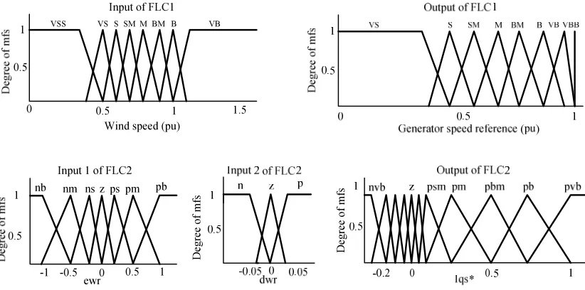
Figure 5 shows the input and output membership function of FLC1 and FLC2.
1
0 0.5
0.5 1 1.5
VSS VS S SM M BM B VB
Input of FLC1
Wind speed (pu)
1 0
ewr Input 1 of FLC2
1
0.5
-1 -0.5 0.5 z ps pm pb ns
nm nb
D
eg
re
e
o
f
m
fs
D
eg
re
e
o
f
m
fs
Figure 5. Membership function of FLC1 and FLC2
The references of stator current
i
ds *and
i
qs *are compared with feedback of stator current
i
ds andi
qs.
Stator current errors are compensated by a PI compensator to obtain thevoltage references in the dq axis
v
dq *. For obtain the references of magnitude and phase angle of voltage reference for SVPWM,
v
dq*
are converted
to
v
αβ. Themagnitude and phase angle ofof SVPWM can be written as follow [20]:
(
2 2)
V
V
m
=
α+
β andθ
=
tan
−1(
V
βV
α)
(14)where
m
andθ
are magnitude and phase angle of the voltage. SVPWM will modulate the gate of converter switch based onm
andθ
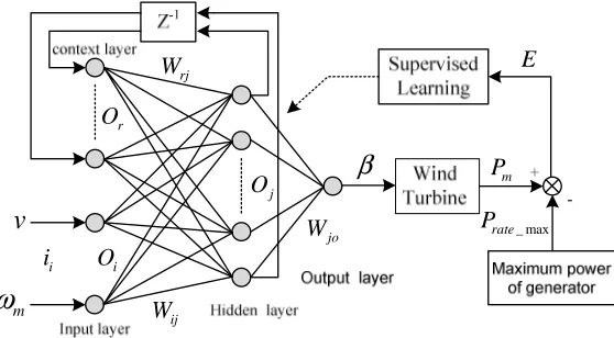
.2.4. Pitch Angle Control Using Recurrent Elman Neural Network (RENN)
RENN. Figure 6 shows the RENN scheme. RENN inputs are wind speed v and generator speed
ω
m, respectively. Output of RENN is pitch angle of wind turbineβ
.v
m
ω
β
i
i
r
O
i
O
j
O
rjW
ij
W
jo
W
m
P
_ max
rate
P
E
Figure 6. RENN scheme to control the pitch angle of wind turbine
RENN consists of Input layer, context layer, hidden layer and output layer [23]. The output of input layer RENN
O
iis defined as:( ) net ( ),
1, 2
O k i k i
i
=
i
=
i
= (15)where
(k)
represents thek
th iteration,i
iis input values of the input layer fork
th iteration. Outputthe context layer
O
rcan be written as [23]:( ) ( 1) ( 1)
,
0 1r r j
O k
=
α
O k−+
O k− ≤α
≤ (16)with
α
is gain feedback in the context layer. The output of hidden layerO
jis activated by tansigtransfer function, which is formulated by :
( )
( ) net ( ) ( )
j j ij i rj r
i r
O k
=
Tansig=
Tansig
W×
O k+
W×
O k
∑
∑
(17)( )
(
2
)
1
1
2
n
Tansig n
=
+
e
−
−
r
=
1, 2,..., 5
andj
=
1, 2,..., 5
where Wij and Wrj are the weight of input neuron to hidden neouron and weight of context
neuron to hidden neuron, respectively. The output layer RENN is activated by linear transfer function, so that the βcan be written as:
( ) net ( )o jo j( )
j
k k W O k
β
=
=
∑
×
(18)with Wjo is the weight of hidden neuron to output neuron. RENN trained with supervised learning
method. In learning process, the Wij, Wrjand Wjo is updated steepest descent algorithm [22], can
be written as:
( 1) ( )
,
, ,x x x x
where ∆Wx is change of the weight, can be formulated by:
(
1)
ij o jo j j i
W δ W O O O
∆
=
− (20)(
1)
rj o jo j j r
W δ W O O O
∆
=
− (21)jo o j
W δ O
∆
=
(22)where
δ
o is error term to be propagated, which is given by:( )
ojo j
j
W O
E
ββ
δ
∂ ∂∂
= −
×
∑
(23)(
)
2 2_ max
0.5
m rate0.5
E
=
P
−
P
=
e
(24)where
E, P
m andP
rate_max are error in learning process, mechanical power of wind turbine and maximum power rate of generator, respectively. Thepitch angle of wind turbine β is trained with wind speed 5 m/s - 20 m/s. Figure 7 shows the performance of training. RENN training reach the error goal in epochs 337 with training error 2.967e-6.Figure 7. Performance of RNN training
3. Results and Analysis
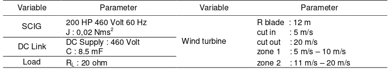
The WECS model has been designed as shown in Figure 2 is simulated using Matlab. Design parameter of WECS is shown in Table 1.
Table 1. Design Parameter of WECS
Variable Parameter Variable Parameter
SCIG 200 HP 460 Volt 60 Hz
Wind turbine
R blade : 12 m J : 0,02 Nms2
cut in : 5 m/s
DC Link DC Supply : 460 Volt cut out : 20 m/s
C : 8.5 mF zone 1 : 5 m/s – 10 m/s
Load RL : 20 ohm zone 2 : 11 m/s – 20 m/s
The first simulation is training the pitch angle β using RENN. The Figure 8 shows the pitch angle
Figure 8. P
Figure 9. Simulation resul
5 10
0 10 20
30 Pitch angle
d
e
g
re
e
Wind speed (m/
Zone 1
0 5 10 15
0 200 400 600 800
Generator speed
Time (second)
rp
m
Pitch angle and power coefficient of wind turbine
sults of zone 1 Figure 10. Simulation re
15 20
gle
m/sec)
Zone 2
5 10
0 0.2 0.4
Pow er coeffic
C
p
Wind speed (m
Zone 1
20 25 30
0 5 10 15
999 1000 1001 1002
generator spe
time (second
rp
m
reference Generator speed
results of zone 2
15 20
fficient
(m/sec)
Zone 2
20 25 30
peed
The power coefficient graph in Figure 8 is obtained from the calculation using the equation (6)-(8). The highest power coefficient found on the pitch angle 0 with
C
p_max 0.48. ForFigure 8, the wind turbine is operated with a reference speed at the
C
p_max point for zone 1 and aconstant 1000 rpm for zone 2. For zone 2, the pitch angle grows large when the wind speed increases. From the Figure 8 can be concluded that the increase in pitch angle of wind turbine will reduce the power coefficient.
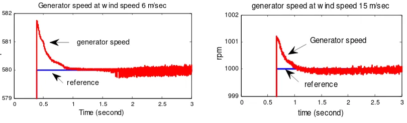
The second simulation, the generator is operated in zone 1 with varying wind speed 6 m/s, 8 m/s and 7 m/s, respectively. Figure 9 shows the results of simulation. The generator speed graph shows validility of the PI-FLC. It can be seen from the actual speed can follow the reference speed. For wind speed 6 m/s, PI-FLC just gives error 1.8 rpm at transient condition and ± 0.2 rpm at steady condition, as shown in Figure 11. The power coefficient graph shows that the values can be constant at maximum point 0.48 in each wind speed variations. Change the power coefficient value occurs only during transient changes in wind speed. The RENN controller gives the pitch angle remains constant 0 with error ± 0.00004º at every variation of wind speed.
Figure 10 shows the simulation results of zone 2 with winds speed 15 m/s, 17 m/s and 19 m/s, respectively. The generator speed graph shows the speed remains constant 1000 rpm on every variation of wind speed. Error of generator speed is shown in Figure 11. The output power graph shows the output power constant at rated generator on every variation of wind speed. It shows the validity of RENN to control the pitch angle of wind turbine. When the wind speed increases, the pitch angle also increases and the power coefficient decrease. It is gives the output power remain constant at maximum power of generator.
Figure 11 shows the error of generator speed for zone 1 and zone 2. For wind speed 6 m/s, the error is 1.8 rpm at transient condition and ± 0.2 rpm at steady state condition. For wind speed 15 m/s, the error is 1.3 rpm at transient condition and ± 0.1 rpm at steady state condition. It is shows that PI-FLC is valid for both operation regions.
This result is better compared with the results in [15]. In [15], the ripple of generator speed ± 0.7 rpm with the ripple of pitch angle ± 0.4 at wind speed 15 m/s.
Figure 11. Error of generator speed
4. Conclusion
Control strategy of MOPT for WECS is developed in this paper. The maximum output power is obtained by controlling the generator speed and pitch angle of wind turbine. The generator speed is controlled using PI-FLC and pitch angle is controlled using RENN. The both controller is valid for two operation regions of wind turbine. It was shown by the simulation results. For zone 1, the output power of generator can be maximized at maximum power coefficient point in each wind speed variations. Speed control using PI-FLC based DFOC method gives the actual speed of generator can follow the reference speed with error 1.8 rpm at transient condition and 0.2 rpm at steady state condition. Pitch angle control of wind turbine using RENN just gives error 0.00004º in each wind speed variations. The same result was also shown by the simulation result for zone 2.
0 0.5 1 1.5 2 2.5 3
579 580 581 582
Generator speed at w ind speed 6 m/sec
Time (second)
rp
m
reference generator speed
0 0.5 1 1.5 2 2.5 3
999 1000 1001 1002
generator speed at w ind speed 15 m/sec
time (second)
rp
m
Generator speed
References
[1] Chen WL, Hsu YY. Controller Design an Induction Generator Driven by a Variable Speed Wind Turbine. IEEE Transaction on Energy Conversion. 2006; 21(3): 625 – 635.
[2] Cardenas R, Pena R. Sensorless Vector Control of induction machines for variable vpeed wind energy applications. IEEE Transaction on Energy Conversion. 2006; 19(1): 196–205.
[3] AJ Mahdi, WH Tang, L Jiang, QH Wu. A Comparative Study on Variable Speed Operations of a Wind Generation System Using Vector Control. International conference on Renewable Energy and Power Quality(ICREPQ).2010.
[4] Senjyu, S Tamaki, N Urasaki, K Uezato, H Higa, T Funabashi, H Fujita. Sensor-less MPPT Control for Wind Generation System with SCIG”, ELSEIVER Renewable Energy. 2008;30: 1-6.
[5] Aouzellag D, Ghedamsi K, Berkouk EM. Network Power Fluc Control of a Wind Generator. ELSEIVER Renewable Energy. 2008; 30: 1-8.
[6] Ahmed T, Nishida K, Nakaoka M. Advanced Control of PWM Converter with Variable Speed Induction Generator. IEEE Industry Application. 2006; 42(4): 934–945.
[7] W Qiao, Wei Z, JM Aller. Wind Speed Estimation Based Sensorless Output Maximization Control for a Wind Turbine Driving a DFIG. IEEE Transactions On Power Electronics. 2008;23(3):1156-1169. [8] Agarwal V, RK Aggarwal, PK Patidar, CK Patki. A Novel Scheme for Rapid Tracking of Maximum
Power Point in Wind Energy Generation Systems Energy Conversion. IEEE Transactions on, 2010; 25(1): 228-236.
[9] R Mittal, KS Sandu, DK Jain. Isolated Operation of Variable Speed Driven PMSG for Wind Energy Conversion System. IACSIT International Journal of Engineering and Technology. 2009; 1(3): 269-273.
[10] Khalil AGA, Lee DC, Seok JK. Variable speed wind generation based on FLC for Maximum Output Power Tracking, 35th Annual IEEE Power Electronic Specialists Conference. Jerman. 2004.
[11] E Adzic, Z Ivanovic, M Adzic. Maximum Power Search in Wind Turbine Based on Fuzzy Logic Control. Journal Acta Polytechnica Hungarica. 2009; 6(1): 131-149.
[12] A Meharrar, M Tioursi, M atti, AB Stambouli. A Variable Speed Wind Generator Maximum Power Tracking Based On ANFIS. Elseiver : Expert Systems with Applications. 2011; 38: 7659–7664. [13] WM Lin, CM Hong. Intelligent Approach To MPPT Control Strategy For Variable-Speed Wind Turbine
Generation System. Elseiver: Energy. 2010; 35: 2440-2447.
[14] CY Lee, YX Shen, Jung CC. Neural Networks and PSO Based MPPT for Small Wind Power Generator. World Academy of Science, Engineering and Technology. 2009;60: 17-23.
[15] H. Camblong. Digital robust control of a Variable Speed Pitch Regulated Wind Turbine for Above Rated Wind Speeds. Elseiver: Control engineering practice. 2008; 16: 946-958.
[16] AS Yilmaz, Z Ozer. Pitch Angle Control in Wind Turbine Above the Rated Wind Speed by Multi-layer Perceptron and RBFNN. Elseiver: Expert System with Applications. 2009; 36: 9767-9775.
[17] WM Lin, CM Hong. A New Elman Neural Network-Based Control Algorithm for Adjustable-Pitch Variable Speed Wind-Energy Conversion Systems. IEEE Transactions On Power Electronics. 2011; 66(2): 1847-1853.
[18] Burton T, Sharpe D, Jenskin N, Borsanyi E. Wind Energy Handbook. West Sussex: John Wiley & Sons. 2001
[19] Boldea I, Nasar SA. The Induction Machine Handbook. Florida: CRC Press. 2002.
[20] Bose KB. Modern Power Electronic and AC Drives. Upper Saddle River: Prentice Hall. 2001. [21] Reznik L. Fuzzy Controller. Oxford: Newnes. 1997.
[22] Widi A. Stabilisator system tenaga berbasis jaringan saraf tiruan berulang untuk sistem mesin tunggal. Journal Telkomnika. 2010; 8(1): 65-72.