UNIVERSITI TEKNIKAL MALAYSIA MELAKA
EFFECT OF SURFACTANT ON EDM OF LOW
CONDUCTIVITY REACTION – BONDED SILICON CARBIDE
This report submitted in accordance with requirement of the Universiti Teknikal Malaysia Melaka (UTeM) for the Bachelor Degree of Manufacturing Engineering
(Manufacturing Process) (Hons.)
by
EHSAN BIN ABU BAKAR B051110220
920109-03-5189
UNIVERSITI TEKNIKAL MALAYSIA MELAKA
BORANG PENGESAHAN STATUS LAPORAN PROJEK SARJANA MUDA
TAJUK: EFFECT OF SURFACTANT ON EDM OF LOW CONDUCTIVITY REACTION – BONDED SILICON CARBIDE
SESI PENGAJIAN: 2014/15 Semester 2
Saya EHSAN BIN ABU BAKAR
mengaku membenarkan Laporan PSM ini disimpan di Perpustakaan Universiti Teknikal Malaysia Melaka (UTeM) dengan syarat-syarat kegunaan seperti berikut:
1. Laporan PSM adalah hak milik Universiti Teknikal Malaysia Melaka dan penulis. 2. Perpustakaan Universiti Teknikal Malaysia Melaka dibenarkan membuat salinan untuk
tujuan pengajian sahaja dengan izin penulis.
3. Perpustakaan dibenarkan membuat salinan laporan PSM ini sebagai bahan pertukaran antara institusi pengajian tinggi.
4. **Sila tandakan ( )
SULIT
TERHAD
TIDAK TERHAD
(Mengandungi maklumat yang berdarjah keselamatan atau kepentingan Malaysia sebagaimana yang termaktub dalam AKTA RAHSIA RASMI 1972)
(Mengandungi maklumat TERHAD yang telah ditentukan oleh organisasi/badan di mana penyelidikan dijalankan)
Alamat Tetap:
11, Lorong Berlian, Kampung Melayu
Majidee, 81100 Johor Bahru,
DECLARATION
I declare that this thesis entitle “effect of surfactant on EDM of low conductivity reaction – bonded silicon carbide” is the result of my own research except as cited in the references. The thesis has not been accepted for any degree and is not concurrently submitted in candidature of any other degree.
Signature : ………
Author’s Name : EHSAN BIN ABU BAKAR
APPROVAL
This report is submitted to the Faculty of Manufacturing Engineering of UTeM as a partial fulfillment of the requirements for the degree of Bachelor of Manufacturing Engineering (process) with Honors. The member of the supervisory committee is as follow:
Signature : ……….
Name : DR LIEW PAY JUN
ABSTRAK
Projek ini menumpu pada penambah baikan prestasi memesin pada silikon karbida tindak balas mengikat bahan seramik menggunakan pemesinan nyahcas elektrik dengan bantuan surfaktan. Perubahan pada kadar penyingkiran bahan (MRR), kekasaran permukaan (SR), kadar kehausan alat (TWR) dan topografi permukaan telah dikaji dengan menggunakan dua jenis surfaktan, iaitu span 20 dan span 80 dengan campuran karbon nanofiber dan minyak EDM. Sebelum eksperimen pemesinan nyahcas elektrik, surfaktan telah dicampur dengan karbon nanofiber bersama minyak EDM, kemudian, campuran itu telah dihomogenkan di dalam penghomogen ultrasonic selama 90 minit. Untuk mengkaji kesan surfaktan, nisbah bahan permukaan kepada karbon nanofiber yang berbeza telah digunakan. Hasil eksperimen menunjukkan bahawa dengan penambahan span 20 dan span 80, kadar kehausan alat (TWR) dan kekasaran permukaan (SR) telah meningkat dengan bertambahnya nisbah surfaktan. Topografi permukaan yang dihasilkan juga menunjukkan dengan bertambahnya nisbah surfaktan, kawah yang dihasilkan semakin besar. Nisbah optimum bagi memperolehi kadar penyingkiran bahan (MRR) paling tinggi adalah 1:1 bagi kedua – dua surfaktan. Sebagai perbandingan, karbon nanofiber yang ditambah dengan span 80 lebih memberi kesan bagi meningkatkan keefisienan memesin silikon karbida tindak balas mengikat berbanding span 20, dengan nisbah optimum 1:1.
ABSTRACT
This project was focusing on improving machining performance of reaction-bonded silicon carbide ceramic material using electrical discharge machine with the aid of surfactant. The changes of material removal rate, tool wear rate, surface roughness and surface topography were investigated on two different surfactants, namely span 20 and span 80 were mixed with carbon nanofiber and EDM oil. Prior to the EDM experiments, the surfactant was mixed with carbon nanofiber and EDM oil, then, the mixture was homogenized using ultrasonic homogenizer for 90 minutes. In order to investigate the effect of surfactant, different ratio of surfactant to carbon nanofiber were used. The experimental results show that with the addition of span 20 and span 80, the tool wear rate and surface roughness were increased with the increasing of surfactant ratio. The surface topography produced also shows that as increasing surfactant ratio, the crater become bigger. The optimum ratio for obtaining the highest material removal rate was 1:1 for both surfactants. In comparison, carbon nanofiber added span 80 was more effective to improve the machining efficiency of reaction bonded silicon carbide compared to span 20, with the optimum ratio 1:1.
ACKNOWLEDGEMENT
DENGAN NAMA ALLAH YANG MAHA PEMURAH LAGI
MAHA PENYAYANG
Alhamdulillah, first and foremost, praise to Allah S.W.T. for giving me the opportunity to complete my Bachelor’s degree Final Year Project from the very beginning until the very end. Without His help, I would not have been able to complete my project. My highest gratitude goes to my supervisor, Dr Liew Pay Jun, without her insight and expertise; I will not be able to finish this research smoothly. Her guidance, concern and patience which were given all the way throughout the project’s duration are very much appreciated.
I also want to express my appreciation to the staff of Faculty of Manufacturing Engineering for their cooperation and contribution throughout the semester in completing this project. Not forget to mention, Mr Raziman, the one that helps me a lot in completing this project.
Lastly, to my beloved parents and families who had been very supportive no matter how hard the times were. Last but not least, to all my friends in Faculty of Manufacturing Engineering, thanks to all.
DEDICATION
To my beloved parents and family:
Abu Bakar bin Sahari (father) Nor Azian binti Ismail (mother)
Fatinah binti Abu Bakar (sister) Ahmad Fadhil bin Abu Bakar (brother)
Ahmad Farid bin Abu Bakar (brother) Ahmad Firdaus bin Abu Bakar (brother)
Ahmad Fahmi bin Abu Bakar (brother) Fatin Aisyah binti Abu Bakar (sister)
TABLE OF CONTENT
CHAPTER 2 : LITERATURE REVIEW
2.1 Electrical Discharge Machining (EDM) 4
2.1.1 The working principle of EDM 5
2.1.2 Material removal rate (MRR) of EDM 10
2.1.3 Spark frequency of EDM 10
2.2 Electrode 11
2.2.1 Electrode polarity in EDM process 12
2.2.2 Electrode wear in EDM process 12
2.3 EDM Dielectric Fluid 13
2.3.1 Functions of the dielectric fluid 14 2.4 Reaction – Bonded Silicon Carbide (RB - SiC) 15
2.4.1 Fabrication process of RB – SiC 16 2.4.2 Material properties of RB – SiC 17 2.4.2.1 Mechanical and chemical properties 18
2.4.2.2 Band gap 18
2.4.2.3 Saturated drift velocity 18
2.4.2.4 Engineering properties 19
2.5 Carbon nanofibre (CNF) 20
2.6 Surfactant used to disperse CNF 22
CHAPTER 3 : METHODOLOGY
3.1 Flow chart of the project 24
3.2 Material preparation 27
3.2.1 Work piece preparation 27
3.2.2 Tool (electrode) preparation 28
3.3 Powder and surfactant preparation 29
3.4 Experimental equipment 30
3.4.1 Electrical discharge machine (EDM) 30
3.4.2 Balance scale 31
3.4.3 Ultrasonic homogenizer 33
3.4.4 Scanning electron microscope (SEM) 34
3.4.5 Surface roughness tester 35
3.5 Experimental condition 35
CHAPTER 4 : RESULT AND DISCUSSION
4.1 Result and data analysis 37
4.1.1 Surface roughness (Ra) 37
4.1.2 Material removal rate (MRR) 40
4.1.3 Tool wear rate (TWR) 43
4.1.4 Surface topography 46
CHAPTER 5 : CONCLUSION AND FUTURE WORK
5.1 Conclusion 49
5.2 Recommendation 50
REFERENCES 51
APPENDICES 54
A Turnitin Report
B Table of Gantt Chart for final year project I C Table of Gantt Chart for final year project II D Observation on the mixture
LIST OF TABLES
2.1 Mechanical properties of silicon carbide 19
2.2 Electrical properties of silicon carbide 20
3.1 Material properties of RB – SiC 27
3.2 Material properties of copper 28
3.3 Ratio, weight and volume of EDM oil for each sample 30
3.4 Experimental condition 36
4.1 Data of surface roughness for span 20 38
4.2 Data of surface roughness for span 80 38
4.3 Data of material removal rate for Span 20 41 4.4 Data of material removal rate for Span 80 41
4.5 Data of tool wear rate for span 20 44
4.6 Data of tool wear rate for span 80 44
LIST OF FIGURES
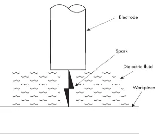
2.1 Concept of EDM 5
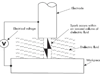
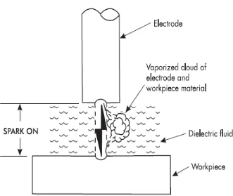
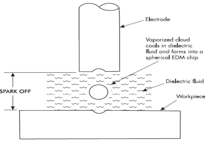
2.2 Spark occurs within a column of ionized dielectric fluid 6 2.3 Spark ON: electrode and work piece material vaporized 8 2.4 Spark OFF: vaporized cloud suspended in dielectric fluid 9 2.5 Spark OFF: vaporized cloud solidifies to form EDM chip 9
2.6 Example of Dielectric Fluid for EDM 13
2.7 Example of RB - SiC products 15
2.8 Carbon nanofibres under scanning electron microscope 20 3.1 Flow chart for chapter 1, chapter 2 and chapter 3 25
3.2 Flow chart for chapter 4 and chapter 5 26
3.3 Dimension of work piece 28
3.4 Dimension of copper electrode 29
3.5 EDM die sinking model Sodick Linear Servo Controller LN 1 31
3.6 Balance scale model Mettler Toledo 32
3.7 Ultrasonic Homogenizer Labsonic model Sartorius Stedim 33
3.8 Scanning electron microscope (SEM) 34
3.9 Surface roughness tester Mitutoyo 35
4.1 Surface roughness (Ra) 40
4.2 Material removal rate (MRR) 43
4.3 Tool wear rate (TWR) 46
4.4 Comparison of span 80 machined surface ratio 1:1, 1:2 and 1:3 47 4.5 Comparison of span 20 machined surface ratio 1:1, 1:2 and 1:3 48
LIST OF ABBREVIATIONS
EDM - Electrical Discharge Machine
MRR - Material Removal Rate
TWR - Tool Wear Rate
Ra - Surface Roughness
CNF - Carbon nanofibre
PMEDM - Powder Mix Electric Discharge Machinin
CHAPTER 1
INTRODUCTION
In this chapter, the background, the problem statement, objectives and scopes of the project are briefly explained.
1.1 Background
Electrical Discharge Machine (EDM) is a non – traditional manufacturing process based on removing material from a part by means of a series of repeated electrical discharges between a tool called electrode and the part being machined in the presence of a dielectric fluid. Electrical Discharge Machine (EDM) provides an effective manufacturing technique that enables the production of a complex shape parts that made from special materials which is difficult to machine by conventional machining process (Luis et al., 2005).
The process doesn’t include mechanical vitality, the hardness, quality and strength of the work piece material do not necessarily influences the removal rate. They are virtually zero forces between the tool and the work piece, so exceptionally sensitive work is possible. The process leaves no burns on the edges. Their use has extended quickly and now it is widely used to produce large body – forming dies in the automotive industry (DeGarmo et al., 2007).
Modern EDM tends to machine semi – conductive material with the assistance of carbon nanofibre (CNF). According to Liew et al., (2013) the addition of carbon nanofibre not only improves the electro discharge frequency, material removal rate, discharge gap, moreover decreases the electrode wear and tip concavity. However, when a high CNF concentration is used, the CNF might not disperse well. Therefore, in this experiment, surfactant will be used to disperse the CNF in order to machine the ceramic material which is Reaction – Bonded Silicon Carbide (RB - SiC).
1.2 Problem Statement
Reaction bonded Silicon Carbide (RB – SiC) is a standout amongst the most guaranteeing engineering ceramics. But, RB – SiC is to a great degree hard to be machined due to its very high hardness. According to Liew et al., (2013), EDM is one of the alternative methods that can machine hard ceramic materials. However, most ceramics including RB –SiC are not conductive enough, which is a critical issue when utilizes EDM. In order to enhance the EDM machinability, researchers have endeavored including conductive powders into the dielectric liquids. Liew et al., (2013) has conducted a research on machining RB – SiC by using EDM with the assistance of carbon nanofibre, and the result was astonishing.
However, when a high concentration of CNF is used, the CNF might not disperse well. According to Leong et al., (2012), the inclusions of surfactants in the nanoparticles samples are modifying the CNF’s surface from hydrophobic to hydrophilic. The CNF nanoparticles tend to repulse each other due to the surface modification. Therefore, in this experiment, surfactant will be added to the dielectric fluid in order to make sure that the carbon nanofibre disperses well in the dielectric fluid by modifying the CNF’s surface. The optimum concentration of carbon nanofibre and the surfactant used will be determined in this experiment
1.3 Objective
In this project, there are several objectives that need to be achieved. They are:
1. To determine the most suitable surfactant and its optimum ratio of carbon nanofibre to surfactant in order to completely disperse carbon nanofibre in the dielectric fluid (oil).
2. To determine the material removal rate (MRR), surface roughness (Ra), tool wear rate (TWR) and surface topography after the machining process of electrical discharge machine (EDM).
1.4 Scope
In this experiment, electrical discharge machine die sinking model Sodick Linear Servo Controller LN 1 was used. Next, carbon nanofibre (CNF) with 150 ~ 200 nm in diameter was used as an additive to the dielectric fluid. Work piece material that was used in this experiment is Reaction Bonded Silicon Carbide (RB - SiC). Then, copper electrode was used as electrode. After that, the dielectric fluid that was used in this experiment is EDM oil. In this experiment, a hole was machined. After the experiment, the surface roughness (Ra), material removal rates (MRR), tool wear rate (TWR) and surface topography were determined. The surfactants that are used in this experiment are span 20 and span 80.
CHAPTER 2
LITERATURE REVIEW
2.1 Electrical discharge machine (EDM)
Electrical Discharge machining (EDM) is the process of machining electrically conductive materials by utilizing accurately controlled sparks that occur between an electrode and work piece in the vicinity of a dielectric liquid. In EDM, the electrode can be considered as the cutting tool. Die - sinking (otherwise called RAM) type EDM machines require the electrode to be machined in the exact inverse shape as the one in the work piece. EDM varies from most chip - making machining operations in that the electrode does not make physical contact with the work piece for material removal. EDM has no tool force since the electrode (cutting tool) does not make physical contact with the work piece. Sparking gap, which the electrode must always be spaced away from the work piece by the distance required for sparking. If the electrode makes contact with the work piece, sparking will cease and no material removal process will occur. There are some EDM machines that do permit the electrode to contact the work piece. Regularly, these sorts of machines are utilized fundamentally for removing broken taps and drills and are not considered die - sinker or wire - cut types of EDM machines (Jameson, 2001).
2.1.1 The working principle of EDM
Figure 2.1: Concept of EDM (Adapted from Jameson, 2001)
The rule of electrical – discharge machining (EDM) is based on erosion of metals by spark discharges, likewise called electro discharge or spark erosion machining. At the point when two current – conducting wires are permitted to touch each other, an arc is produced. When we look carefully at the point of contact between the two wires, permitted has been eroded away, leaving a small crater. It was not known until 1940s, a machining process based on this principle was developed, despite the fact that this phenomenon has been known since the revelation of electricity. The EDM process has turned into a standout amongst the most essential and broadly acknowledged production technologies in manufacturing industries (Kalpakjian et al., 2003).
The EDM system (Figure 2.1) consists of a shaped tool (electrode) and the work piece, which are connected to a dc power supply and placed in a dielectric (electrically non - conducting) fluid. A magnetic field causes suspended particles in the dielectric fluid to concentrate when a voltage is applied to the tool, in the end forming a bridge for current to flow to the work piece. An intense electrical arc is then generated, causing sufficient heating to melt a portion of the work piece and usually some of the tooling material as well. In addition, the dielectric fluid is heated rapidly, causing evaporation of the fluid in the arc gap; this evaporation, in turn, increase the resistance of the interface, until the arc can no longer be maintained. Once the arc is interrupted, heat is removed from the gas bubble by the surrounding dielectric fluid, and the bubble collapses (cavitates). The flow of the dielectric fluid and associated shock wave flush debris from the surface and entrain any molten work piece material into the dielectric fluid (Kalpakjian et al., 2003).
Figure 2.2: Spark occurs within a column of ionized dielectric fluid (Adapted from Jameson, 2001)
EDM is a thermal process; material is removed by heat. High temperature is presented by the stream of electricity between the electrode and work piece in the form of spark. Material that are put at the closest point between the electrode and work piece, are heated to the point where the material vaporizes, this is where the spark begins and ends. While the electrode and work piece should never feel more than warm to the touch during EDM, the area where each spark occurs is very hot. The area that heated by the spark is very minimal; therefore, the dielectric fluid quickly cools the vaporized material, electrode and work piece surfaces. However, it is feasible for metallurgical changes to occur because of the spark heating the work piece surfaces. The main characteristic of dielectric fluid is that it is an electrical insulator until enough electrical insulators except at the closest points between work piece and electrode. At these points, spark occurs by the dielectric fluid to change from an insulator to a conductor causes by the sparking voltage. Ionization point is the place the time at which the fluid changes into an electrical conductor. At the point when the spark is turned off, the dielectric fluid deionizes and the fluid returns to being an electrical insulator. This change of the dielectric fluid from an insulator to a conductor, and then back to insulator, happens for each spark. Figure 2.2 shows that the EDM spark occurring within an ionized column of the dielectric fluid (Jameson, 2001).
The dielectric fluid used in EDM machines provides important functions in the EDM process. They are:
a) Controlling the sparking – gap spacing between the electrode and work piece. b) Cooling the heated material to form the EDM chip.
c) Removing EDM chips from the sparking area.
A little measure of electrode and work piece is vaporized as each spark occurs. A cloud is the place where the vaporized material is positioned in the sparking gap between the electrode and the work piece. At the point when the spark is turned off, the vaporized cloud has a tendency to turn into a solid. Each spark then produces an EDM chip or a
very tiny hollow sphere of material made up from the electrode and work piece material. In Figure 2.3, Figure 2.4 and Figure 2.5 will show the spark producing vapour cloud, the cloud in suspension, and the vaporized cloud being cooled and forming into an EDM chip (Jameson, 2001).
Figure 2.3: Spark ON: electrode and work piece material vaporized (Adapted from Jameson, 2001)
Figure 2.4: Spark OFF: vaporized cloud suspended in dielectric fluid (Adapted from Jameson, 2001)
Figure 2.5: Spark OFF: vaporized cloud solidifies to form EDM chip (Adapted from Jameson, 2001)
2.1.2 Material Removal Rate (MRR) of Electrical Discharge Machining
The EDM process can be used on any material that can conduct electricity. The melting point and the latent heat of melting are important physical properties that determine the volume of metal removed per discharge. As these quantities increases, the rate of material removal decreases and vice versa. The material removal rate can be estimated from the approximate empirical formula:
MRR = 4 x 10⁴ ITw-1.23 (2.1)
Where MRR is in mm3/min, I is the current in amperes, and Tw is the melting point of the work piece in oC. The work piece is hold by a fixture within the tank that contains dielectric fluid, and its movements are controlled by numerically controlled systems. The gap between the tool and the work piece (overcut) is critical. Thus, the downward feed of the tool is controlled by a servomechanism, which automatically maintains a constant gap. Since the process doesn’t involve mechanical energy, therefore, the hardness, strength, and toughness of the work piece material do not necessarily influence the removal rate. To control the removal rate, the frequency of discharge or the energy per discharge, the voltage, and the current are varied. The removal rate and surface roughness increase with increasing current density and decreasing frequency of sparks (Kalpakjian et al., 2010).
2.1.3 Spark Frequency of EDM
ON time and OFF time for an EDM – power supply is normally set in a range from 1 to 250 microseconds. Figure 10 shows the normal spark frequency range if EDM – power supplies based on equal spark – ON/OFF microsecond timing. The spark frequency