PARKING CONTROL SYSTEM USING MICROPROCESSOR
HANI AIMI BINTI HASHIM
This report is submitted in partial fulfillment of the requirements for the award of Bachelor of Electronic Engineering (Industrial Electronics) with Honors
Faculty of Electronic and Computer Engineering Universiti Teknikal Malaysia Melaka
UNIVERSTI TEKNIKAL MALAYSIA MELAKA
FAKULTI KEJURUTERAAN ELEKTRONIK DAN KEJURUTERAAN KOMPUTER
BORANG PENGESAHAN STATUS LAPORAN
PROJEK SARJANA MUDA II
Tajuk Projek : PARKING CONTROL SYSTEM USING MICROPROCESSOR
Sesi Pengajian : 2010/2011
Saya HANI AIMI BT HASHIM
mengaku membenarkan Laporan Projek Sarjana Muda ini disimpan di Perpustakaan dengan syarat-syarat kegunaan seperti berikut:
1. Laporan adalah hakmilik Universiti Teknikal Malaysia Melaka.
2. Perpustakaan dibenarkan membuat salinan untuk tujuan pengajian sahaja.
3. Perpustakaan dibenarkan membuat salinan laporan ini sebagai bahan pertukaran antara
institusi pengajian tinggi.
4. Sila tandakan ( √ ) :
SULIT*
(Mengandungi maklumat yang berdarjah keselamatan atau kepentingan Malaysia seperti yang termaktub di dalam AKTA RAHSIA RASMI 1972)
TERHAD* (Mengandungi maklumat terhad yang telah ditentukan oleh
organisasi/badan di mana penyelidikan dijalankan)
TIDAK TERHAD
Disahkan oleh:
__________________________ ___________________________________
iii
“I hereby declare that this report is the results of my own work except for quotes as cited in the reference.”
Signature : ………
Author : HANI AIMI BT HASHIM
iv
“I hereby declare that I have read this report and in my opinion this report is sufficient in
terms of the scope and quality for the award of Bachelor of Electronic Engineering
(Industrial Electronics) With Honors”
Signature : ………
Supervisor’s name : MS. NURMALA IRDAWATY BINTI HASSAN
v
Dedicated to my parents, Hashimn bin Omar and Fatimah binti Osman ,my siblings,
vi
ACKNOWLEDGEMENT
First of all, I would like to thank God for his blessing, and I also want to express my deepest gratitude to my supervisor Ms. Nurmala Irdawaty binti Hassan for support and guidance throughout this project running and completion of this report.
My deepest appreciation also goes out to Miss Muzalifah binti Haji Mohd Said
who gave me many needed support, encouragement and help throughout my project’s
improvement, not to forget, thanks to my family and fellow friends who encouraged me.
Finally, thank you to all those involved directly and indirectly helping me out
during my PSM 1 & PSM II which I can’t state out every one of them. A special
vii
ABSTRACT
The purpose of this project is to develop a parking system that can solve the problem regarding the availability of parking space with high efficiency through application of microprocessor. The objective of this project is to develop a prototype which is fully functional, usable and can sufficiently accurate follow the available number of free space. This parking system will be able to detect and count the incoming and outgoing vehicles (cars/vans) at a parking space and at the same time each of the parking lot will provide some indicators to indicate the availability of the parking area. In addition, this research also includes the mechanism on how the FULL indicator will be triggered by a chosen metal detector. As an early indication for available parking space, a screen will be posted in front of the ticket machine as a way to visualize and information medium to drivers. This screen will be used Visual Basic software to design the required output that should be display on the screen and the display will be updated time to time depend on the availability of parking space. Furthermore, the drivers
viii
ABSTRAK
Tujuan projek ini itu adalah bagi membangunkan satu sistem tempat letak kereta yang dapat menyelesaikan masalah-masalah mengenai kekosongan tempat letak kereta dengan kecekapan yang lebih tinggi melalui Programmable Logic Controller (PLC). Objektif projek ini adalah untuk membina sebuah prototaip yang berfungsi sepenuhnya, dapat digunakan dan tepat mengikut jumlah kekosongan .Sistem tempat letak kereta ini mampu mengesan dan mengira kenderaan keluar masuk pada tempat letak kereta dan pada masa yang sama juga, setiap tempat letak kenderaan akan menyediakan beberapa penunjuk untuk menunjukkan kekosongan kawasan tempat letak. Tambahan lagi, penyelidikan ini juga termasuk mekanisme tentang bagaimana penunjuk
‘FULL’ itu akan diaktifkan oleh satu pengesan logam yang dipilih. Sebagai satu
penunjuk awal untuk kekosongan tempat letak kenderaan, sebuah skrin akan diletakkan di depan mesin tiket sebagai satu cara untuk memvisualkan dan menjadi perantara maklumat untuk pemandu-pemandu. Skrin ini akan menggunakan asas visual untuk mereka keluaran yang dikehendaki dan dipaparkan melalui skrin. Paparan itu akan
CHAPTER 1
INTRODUCTION
1.0 Project Introduction
The conventional car park system normally just have some signboard of direction of vehicles need to follow. It does not have any display panel and it cannot show the total vacancy of parking lot in the parking area. The drivers has taken risk to seek either there are any vacancy or not. By developing a parking system that includes the availability of vacancy display can help
the drivers as a user to shorter their searching time. This Microprocessor based Parking system is an electronic application will be improved the conventional parking system by using suitable sensor and display panel.
2
1.1 Project Objectives
1.2.1 To build a system based on Microprocessor based parking system.
1.2.2 To design a system that can detect any changes of number of available parking space and inform the drivers through Indicators.
1.2.3 To build a mini prototype of this parking system.
1.2.4 To build parking lot by using numeral system..
1.2 Problem Statement
3
1.3 Scope of Work
SOFTWARE
i. Counting the free parking space
The system must able to calculate the number of available parking space. A sensor will be used to sense a vehicle and will be an input to the counting program. Increasing or decreasing the total number of free parking space (output) is depends on the number of car entering and leaving the
parking area [3].
ii. Display number of available parking space and display the info of available parking space through a screen.
The number of free parking space will be displayed on a 7 segment as the output. The 7-Segments will be displayed at the main Entrance/Exit. It also needed to ensure the hardware can trigger the Visual Basic on a screen that will display the total vacancy of parking lots [3].
iii. Build a parking system that can operate at real time.
4
iv. To build parking lot by using numeral system
CHAPTER 2
LITERATURE REVIEW
2.0 Introduction
For this chapter, the whole description is about methodology choice, techniques applied and technology used in completing process of Parking Control System by using Microprocessor. A methodology tells developer what he or she has to do, to manage the projects from start to finish. It describes every step in the project life cycle in depth, so developer knows exactly which tasks to complete, when and how. Whether they are an expert or a novice, it helps in completing tasks faster than before.
2.1 Literature Review
This part will focus to explain about the processes that used when undertaking this project, and survey that carried out to incorporate and renew under total that is in project that earlier. In this part, information of component that used and that component advantage to this project will be explained.
17
2.2 Car parking knowledge
Nowadays, the conventional parking system that preparing need to be confirmed own system that can facilitate user to attract consumer interest. Although system that is in
supermarket now has been dignified but still is weakness that need to be repaired. For example present system never mentions proper place Consumer Park their vehicles. By renew this system, it stated to parking consumer that they achieve. This can facilitate user and able to save time consumer to find parking vacancy.
2.2.1 Project Significant
This parking system that renewable, provide LCD display to facilitate consumer know
the true position of vacancy parking. Consumer only required to key in the car number and LCD display the parking that available. Parking guidance and information can improve network efficiency significantly, reported benefits include able to save time consumer to find vacancy parking, apart from that can facilitate user know their parking and also consumer no need go around and around to find the available parking.
2.3 LCD (Liquid Crystal Display).
The LCD is used to display the output of the devices. This LCD is a 5x8 dots Crystal Display controller/driver which is manufacturer by Vishay. It is suitable for any portable battery driven product that required low power because the power supply for this LCD is about (2.7V to 5.3V). The LCD 016M002B dot matrix liquid crystal controller and driven LSI able to display alphanumeric, Japanese kana character and symbols. It can b configured to driver a dot matrix liquid crystal display under the control of a 4 or 8 bit microprocessor. A single LCD-016M002B contains the display controller/driver, so the output pins was simplified to 16 pins only.
18
Figure 1- LCD - 016M002B
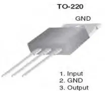
2.4 Voltage Regulator LM7805
Figure 2 Pin Assigment of Voltage Regulator
The LM78XX series of three terminal positive regulators are available in the TO-220 package and with several fixed output voltages, making them useful in a wide range of
applications. Each type employs internal current limiting, thermal shut down and safe operating area protection, making it essentially indestructible. If adequate heat sinking is provided, they can deliver over 1A output current. Although designed primarily as fixed voltage regulators, these devices can be used with external components to obtain adjustable voltages and currents.
19
2.4.1 Features
• Output Current up to 1A
• Output Voltages of 5, 6, 8, 9, 10, 12, 15, 18, 24
• Thermal Overload Protection • Short Circuit Protection
• Output Transistor Safe Operating Area Protection
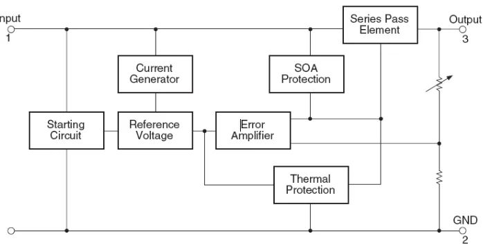
2.4.2 Block Diagram
Figure 3 Block Diagram of Voltage Regulator
2.43 Absolute Maximum Ratings
Absolute maximum ratings are those values beyond which damage to the device may occur. The datasheet specifications should be met, without exception, to ensure that the system design is reliable over its power supply, temperature, and output/input loading variables.
20
Table 1 : Absolute Maximum Ratings
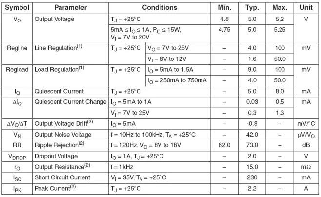
2.4.4 Electrical Characteristics (LM7805)
Load and line regulation are specified at constant junction temperature. Changes in VO due to heating effects must be taken into account separately. Pulse testing with low duty is used. These parameters, although guaranteed, are not 100% tested in production.
Table 2 : Electrical Characteristic LM (7805)
21
Figure 4 : Adjustable Output Regulator
IRI ≥ 5IQ
VO = VXX (1+R2/R1) + IQR2
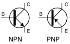
2.5 Transistor
There are two types of standard transistors, NPN and PNP, with different circuit symbols. The letters refer to the layers of semiconductor material used to make the transistor. Most transistors used today are NPN because this is the easiest type to make from silicon. The leads are labeled base (B), collector (C) and emitter (E).
Figure 5 : Transistor Circuit Symbols
22
2.5.1 Transistor Current
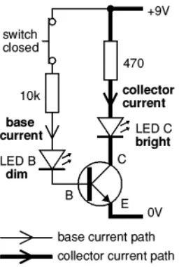
Figure 6 : Transistor Current
2.5.2 The small base current controls the larger collector current.
When the switch is closed a small current flows into the base (B) of the transistor. It is just enough to make LED B glow dimly. The transistor amplifies this small current to allow a larger current to flow through from its collector (C) to its emitter (E). This collector current is large enough to make LED C light brightly.
When the switch is open no base current flows, so the transistor switches off the collector current. Both LEDs are off.
2.5.3 A transistor amplifies current and can be used as a switch.
This arrangement where the emitter (E) is in the controlling circuit (base current) and in the controlled circuit (collector current) is called common emitter mode. It is the most widely used arrangement for transistors so it is the one to learn first.
23
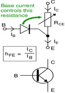
2.5.4 Functional model of an NPN transistor
The operation of a transistor is difficult to explain and understand in terms of its internal structure. It is more helpful to use this functional model:
The base-emitter junction behaves like a diode.
A base current IB flows only when the voltage VBE across the base-emitter junction is
0.7V or more.
The small base current IB controls the large collector current Ic. Ic = hFE × IB (unless the transistor is full on and saturated)
hFE is the current gain (strictly the DC current gain), a typical value for hFE is 100 (it has no units because it is a ratio)
The collector-emitter resistance RCE is controlled by the base current IB:
o IB = 0 RCE = infinity transistor off o IB small RCE reduced transistor partly on
o IB increased RCE = 0 transistor full on ('saturated')
Figure 7 : NPN Transistor