UNIVERSITI TEKNIKAL MALAYSIA MELAKA
DEVELOPMENT OF A SOLAR-POWERED CONTROLLER FOR
DRAINAGE SYSTEM WITH WATER TREATMENT
This report submitted in accordance with requirement of the Universiti Teknikal Malaysia Melaka (UTeM) for the Bachelor Degree of Manufacturing Engineering
(Robotic and Automation) with Honours.
by
MOHD IBRAHIM BIN RAHAMAT B050810336
UNIVERSITI TEKNIKAL MALAYSIA MELAKA
BORANG PENGESAHAN STATUS LAPORAN PROJEK SARJANA MUDA
TAJUK: Development of Solar-Powered Cont roller for Drainage Syst em Wit h Wat er Treat ment
SESI PENGAJIAN: 2010/ 11 Semest er 2
Saya MOHD IBRAHIM BIN RAHAMAT
mengaku membenarkan Laporan PSM ini disimpan di Perpust akaan Universit i Teknikal Malaysia Melaka (UTeM) dengan syarat -syarat kegunaan sepert i berikut :
1. Laporan PSM adalah hak milik Universit i Teknikal Malaysia Melaka dan penulis. 2. Perpust akaan Universit i Teknikal Malaysia Melaka dibenarkan membuat salinan
unt uk t uj uan pengaj ian sahaj a dengan izin penulis.
3. Perpust akaan dibenarkan membuat salinan laporan PSM ini sebagai bahan pert ukaran ant ara inst it usi pengaj ian t inggi.
4. **Sila t andakan (√)
SULIT
TERHAD
TIDAK TERHAD
(Mengandungi maklumat yang berdarj ah keselamat an at au kepent ingan Malaysia yang t ermakt ub di dalam AKTA RAHSIA RASMI 1972)
(Mengandungi maklumat TERHAD yang t elah dit ent ukan oleh organisasi/ badan di mana penyelidikan dij alankan)
(TANDATANGAN PENULIS)
DECLARATION
I hereby, declared this report entitled Development of Solar-Powered for Drainage System With Water Treatment is the results of my own research except as cited in
references.
Signature : ……….
Author’s Name : ………
APPROVAL
This report is submitted to the Faculty of Manufacturing Engineering of UTeM as a partial fulfillment of the requirements for the degree of Bachelor of Manufacturing Engineering (Robotic and Automation) with Honours. The member of the supervisory committee is as follow:
………
i
ABSTRAK
ii
ABSTRACT
iii
DEDICATION
I would like to dedicate this report for my lovely mother and family, all lecture in manufacturing engineering department, all staff, and also for all my friends. They keep me in track and encourage me to do my best.
iv
ACKNOWLEDGEMENTS
First of all, I would like to express my gratitude to Mr. Ahmad Yusairi Bin Bani Hashim
as a PSM supervisor. This is for her invaluable support, encouragement, supervision, ideas, opinions and suggestions throughout this PSM. Without her moral support and continuous guidance, this project will not complete successfully.
My deepest grace and thank goes to my beloved mother, Mrs. Zainon Binti Abd Manap for their love and who gave me an endless supports and patience toward the completion of the dissertation. Their supports and advices have boosted up my spirit to do the best in my final year project. I also wish to thank to my siblings for their support and understanding during my final year project.
v
2.2.1 History of the Photoelectric Phenomenon 5
vi
2.5.1.f) Changing the Direction of Rotation of Motor Armature 17
2.5.1.g) Example of DC Motor 18
2.5.2 AC Motor 20
5.2.2.a) Introduction of Amplitude Current Motor 20
5.2.2.b) AC Motor Principle 21
2.5.2.c) Basic of AC Motor Cross Sectional 22
2.6. Motor Torque 22
2.9.3 Solar Power Telecommunication Station 27
2.10 Review 28
3: METHODOLOGY 30
vii
3.4.4 Testing, Analysis, Improvement and Modification Stage 37
4: DESIGN AND DEVELOPMENT 39
4.1 Introduction 39
4.2 Electronic Circuit Design 39
4.2.1 Motor Rotational Control Circuit 40
4.2.2 Automatic Recharge Battery Circuit 42
4.3 Station Design 45
4.3.1 Box for Store Electronic Circuit 46
4.3.2 Station Body 48
4.4.1 Motor Rotational Control Circuit 52
4.4.2 Automatic Recharge Battery Circuit 53
viii
5 : RESULT AND DISCUSSION 60
5.1 Introduction 60
5.2 Result 61
5.2.1 Motor Rotation 61
5.2.2 Motor Torque 62
5.2.3 Battery Charging Evaluation 64
5.2.4 Water Sensor 67
5.3 Discussion 67
5.3.1 Motor circuit 67
5.3.2 Automatic Recharge Battery Circuit 69
5.3.3 Water Sensor 69
5.3.4 Stop Cork 69
5.3.5 Concluding Remarks 69
6: CONCLUSION AND RECOMMENDATION 70
6.1 Conclusion 70
6.2 Recommendation 71
ix
LIST OF TABLES
Table 4.1 Components list on Automatic Recharge Battery Circuit 43
x
LIST OF FIGURES
Figure 2.1: Solar Panel 5
Figure 2.2: The photoelectric effect experiment 6
Figure 2.3: Photovoltaic module operational diagrams 7
Figure 2.4: AC Generating System 9
Figure 2.5: Battery Form 10
Figure 2.6: Battery Circuit Diagram 11
Figure 2.7: Example of Battery Structure-Dry Cell 12
Figure 2.8: DC Motor Part 18
Figure 2.9: Illustration on how the DC motor working principle 15
Figure 2.10: DC motor circuit 16
Figure 2.11: Shunt DC motor circuit 16
Figure 2.12: a. Connection diagram of a dc compound motor. 17 b. Schematic diagram of the motor 17 Figure 2.13: Circuit(a,b,c) for changing the DC motor rotating direction 18
Figure 2.14: Power Window Motor 18
Figure 2.15: Stepper Motor 19
Figure 2.16: Servo Motor 20
Figure 2.17: AC Motor Cross Sectional 22
Figure 2.18: Motor circuit control 24
Figure 2.19: Sensor detect water ON and Detect water OFF 25
Figure 2.20: Voltage Regulator Circuit 25
Figure 2.21: Solar Power Indicator Light 26
Figure 2.22: Solar Power Weather Station 27
xi
Figure 3.1: PSM 1 Gantt Chart 31
Figure 3.2: PSM 2 Gantt Chart 32
Figure 3.3: Flow chart of the overall project process 33 Figure 3.4: Flow chart of the title selection and approved stage 34 Figure 3.5: Flow chart of the research and data collection stage 35
Figure 4.4: Solar charger schematic circuit 44
Figure 4.5: Circuit design by using Livewire Professional Edition 45
Figure 4.6: Box sketching 47
Figure 4.7: Box re-draws by using Solid Work 47
Figure 4.8: L-Bracket 48
Figure 4.9: Hollow metal bar 49
Figure 4.10: Sketch of based, pillar and box holder after joining 49
Figure 4.11: Whole sketch of station 50
Figure 4.12: Solid Work full drawing 50
Figure 4.13: Soldering iron 51
Figure 4.14: Soldering lead 51
Figure 4.15 : Soldering process 52
Figure 4.16 : Motor rotational circuit 52
Figure 4.17 : Component testing and measuring 53
Figure 4.18 : Finish circuit 54
Figure 4.19 : Circuit assembly inside the box 54
Figure 4.20 : Full assemble for electronic circuit 54
Figure 4.21 : Picture blade cutting 55
Figure 4.22 : Drawing for cutting the acrylic and zink plate 56
xii
Figure 4.24: Clamping process 57
Figure 4.25: Welding Process 58
Figure 4.26: Hand grinder 58
Figure 4.27: Final station 59
Figure 5.1 : Motor with limit switch picture 61
Figure 5.2 : Evaluating process 64
Figure 5.3 : Voltage form in battery after charging 65
Figure 5.4 : Current form in battery after charging 66
Figure 5.5 : Water sensor 67
Figure 5.6 : Old circuit 68
xiii
1
CHAPTER 1
INTRODUCTION
1.1 Overview
An introduction is a beginning section which states the purpose and goals of the following writing. This section is usually interesting and it intrigues the reader and causes reader to read on. This chapter is about introducing the research of this project. The project is research and development about drainage system for paddy-field. The drainage system typically refers to the method for control the water level on that paddy-field. Also, it is will state the problems occur during the development, the objectives of this project and expected result at the end of the semester.
1.2 Introduction
In Malaysia, some drainage system for paddy-field was prepared by government to full their paddy-partition with water. This make paddy farmer not worried to get water from natural river and pump the water by water pump to their paddy-field. This system only have small pipe from the drainage to the paddy-field. This small pipe doesn’t have any device to control the water flow. Manual methods are use for control that water to past that’s pipe and flow to the personel paddy-field from main drainage.
2
pipe with water and use the vacuum concept for maintain the water flow. This method also causes farmer need to open and closed the pipe by bung it using un-used cloth, wood or plastic to control the water flow. Farmer also needs to wait in long time to ensure the water was enough and take out the ‘L’ pipe. This situation cause farmer difficult to do other activities because need to wait.
It is important to develop a system that makes farmer no need to wait at in long time to full their paddy-partition by water. This system is using solar panel to collect the power for drive a direct current motor. Direct current motor will assemble to the inlet outlet valve to operate it. Battery will use to save the solar power for system operate in cloudy weather and night. This system also will stabilize the level of water in the paddy-field.
1.3 Problem Statement
3 1.4 Objective
The objective of this project are:
1. To develop a controller for Drainage System with Water Treatment. 2. To design a limit switch that use for maintain the level of water. 3. To design circuit for re-charge the battery voltage by using solar panel.
1.5 Project Scope
1. This project only focus on developing a controller for control the rotation of DC motor where assemble for Drainage System With Water Treatment. 2. Solar panel will be use for supply a power to operate this project.
1.6 Expected Result
4
CHAPTER 2
LITERATURE REVIEW
2.1 Overview
A literature review is a body of text that aims to review the critical points of current knowledge including substantive findings as well as theoretical and methodological contributions to a particular topic. Most often associated with academic-oriented literature, such as theses, a literature review usually precedes a research proposal and results section. This section will review a logical flow of ideas current and relevant references with consistent, appropriate referencing style proper use of terminology and an unbiased and comprehensive view of the previous research on the topic. For this reports, literature review will explain about the related equipment, theory, formula, electronic circuit and mechanical part that’s use for this project.
2.2 Solar Power
5
Solar cell do not store electricity, but the batteries can be used to store the energy. One of the most fascinating aspects of solar cell is their ability to convert the most abundant and free form of energy into electricity, without moving parts or components and without producing any adverse form of pollution that affect the ecology, as is associated with most known forms of nonrenewable energy production methods, such as fossil fuel, hydroelectric, or nuclear energy plants.
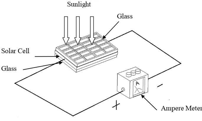
Figure 2.1: Solar Panel (Personel Capture August 2010).
2.2.1 History of the Photoelectric Phenomenon
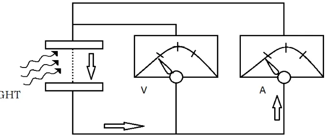
In late of the century, physicist discover a phenomenon, when light is incident on liquids or metal cell surfaces, electrons are released. However, no one had an explanation for this bizarre occurrence. At the turn of the century, Albert Einstein provided a theory for this which won him the Nobel Prize in physics and laid the groundwork for the theory of the photoelectric effect. Figure 1.0 shows the photoelectric effect experiment. When light is shone on metal, electrons are released. These electrons are attracted toward a positively charged plate, thereby giving rise to a photoelectric current.
6
consequently led to the discovery of transistor in the 1950s and to the development of semiconductor electronics.
Figure 2.2: The photoelectric effect experiment (Solar Power in Building Design 2008).
2.2.2 Solar Cell Physics
Most solar cell are constructed from semiconductor material, such as silicon(the fourteen element in the Mendeleyev table of elements). Silicon is a semiconductor that has the combined properties of a conductor and an insulator. Metals such as gold, copper, and iron are conductor. They have loosely bound electrons in the outer shell or orbit of their configuration. These electrons can be detached when subjected to an electric voltage or current. On the contrary, atoms of insulators, such as glass, have very strongly bonded electrons in the atomic configuration and do not allow the flow of electrons even under the severest application of voltage or current. Semiconductor materials, on the other hand, bind electrons midway between that of metals and insulators.
7
The N-type material has a propensity to lose electrons and gain holes, so it acquires a positive charge. The P-type (positive type) material has a propensity to lose and gain electrons, so it acquires a negative charge.
When N-type and P-type doped silicon wafers are fused together, they form a PN junction. The negative charge on P-type material prevents electrons from crossing the junction, and the positive charge on the N-type material prevents hole from crossing the junction. A space created by the P and N, or PN, wafers create a potential barrier across the junction.
2.2.3 Solar Cell Electronics
An electrostatic field is produced at a PN junction of solar cell by impinging photons that create 0.5V of potential energy, which is characteristic of most PN junction and all solar cell. This miniscule potential resembles in function a small battery with positive and negative leads. These are then connect front to back in series to achieve higher voltages.