UNIVERSITI TEKNIKAL MALAYSIA MELAKA
DEVELOPMENT OF A PROTOTYPE FOR SOLAR POWERED
SMART WATER WASTE UNIT (OVERALL STRUCTURE)
This report is submitted in accordance with the requirement of Universiti Teknikal Malaysia Melaka (UTeM) for the Bachelor of Manufacturing Engineering
Technology (Product Design) with Honours
by
MUHAMMAD YUSRAN BIN MUHAIYUDDIN B071210349
900610-10-5701
DECLARATION
I hereby, declared this report entitled “Development of a Prototype for Solar Powered Smart Water Waste Unit (Overall Structure)” is the results of my own
research except as cited in references.
Signature : ……….
Author‟s Name : ……….
APPROVAL
This report is submitted to the Faculty of Engineering Technology of UTeM as a partial fulfilment of the requirements for the degree of Bachelor of Manufacturing Engineering Technology (Product Design) with Honours. The member of the supervisory is as follow:
i
ABSTRACT
ii
ABSTRAK
iii
ACKNOWLEDGEMENT
In this section, I would like to give my deepest gratitude to my parents, Muhaiyuddin Bin Ahmad and also Madam Zaini Binti Baba that always support and believe in the thing that I am done. Very special thanks to my dearest supervisor, Madam Umi Hayati Binti Ahmad whose help, guide and encourage me to coordinate my project especially in completing this report. Without her patience, advices, and also guidance, I might be stuck and lost from the project that I am doing. As this project is my last task before I stop my journey as a bachelor student, I fell honoured to express my appreciation to all those who gave me the possibility to comprehend this project report especially my dear housemate. They keep reminding me to settle down my work in an appropriate way and also help me in generating a new idea for the Solar Panel Smart Water Waste Unit (Overall Structure). Further ado, I also want to deliver a special thanks to my classmate that helps me in making this project done. I also would like to thanks to the other supervisors as well as the panels especially in my project presentation in helping me to improve my presentation skills with their statement, comment, and tips.
Sincerely,
iv
DEDICATION
Especially for beloved father and mother: Muhaiyuddin Bin Ahmad
Zaini Binti Baba
To all my siblings:
Muhammad Hilman Bin Muhaiyuddin Muhammad Syukran Bin Muhaiyuddin Muhammad Dzarfan Bin Muhaiyuddin
Syajaratul Dur Binti Muhaiyuddin Rabiatul Dur Binti Muhaiyuddin
v
List Of Abbreviations, Symbols and Nomenclature xii
CHAPTER 1 INTRODUCTION 1
1.0 Introduction 1
1.1 Background 1
1.2 Objective 2
1.3 Scope 2
1.4 Problem Statement 2
CHAPTER 2 THEORETICAL BACKGROUND 4
2.1 Hull Structure Design 4
2.1.1 Hull Structure Design Policy 4
2.1.2 Basic Idea of Hull Structure Design 5
2.1.3 Design Flow 6
2.1.4 Boat Hull Design 7
2.1.5 Gross Tonnage Formulation (Twin Hull Vessels) 9
2.2 Trends of Smart Water Waste Unit 10
2.2.1 Baltimore Water Wheel 10
2.2.2 Sv Newark Bay‟s 11
2.2.3 Ocean Cleanup Array 12
2.3 Layout of Smart Water Waste Unit 12
2.3.1 Layout of Baltimore Water Wheel 12
vi
2.4.1 Structure of Sv Newark Bay‟s 13
2.4.2 Structure of Water Witch 14
2.5 Mechanical 15
2.5.1 Water Wheel 15
2.5.1.1 Types of Water Wheel 15
2.5.1.2 Horizontal Water Wheel 16
2.5.1.3 Vertical Water Wheel 16
2.5.2 Conveyor Types and Conveyor System 18
2.6 Solar Panel Arrangement 20
2.7 Material of Boat 21
2.7.1 Strength 22
2.7.2 Fibreglass Properties 23
2.8 Buoyancy 26
2.8.1 Buoyancy Boat 27
2.8.2 The Basic of Stability: Buoyancy and Gravity 28
2.8.3 How the Centre Of Gravity Moves 29
2.9 Stability 30
2.9.1 Static Stability 30
2.9.2 Form Stability (Effect of Section Shape) 31
2.10 Cad Design Software 32
2.10.1 Solidwork Software 32
2.11 CAE Analysis 33
2.11.1 FEA (Finite Element Analysis) 33
2.11.2 Applications of the Finite Element Method 33
2.11.3 Advantages of the Finite Element Method 34
2.11.4 CAE Analysis Software 35
2.11.4.1 General-purpose Advantages and Disadvantages 36
CHAPTER 3 METHODOLOGY 37
3.1 Introduction 37
3.2 Methodology Process Flow 38
3.2.1 Concept Design 39
vii
3.2.5 Buoyancy and Stability 43
3.2.5.1 Calculation of Buoyancy 43
3.2.5.2 Stability 44
3.2.6 Built Up Prototype 44
CHAPTER 4 Development of a prototype for Solar Powered Smart Water
Waste Unit (Overall Structure) 45
4.1 Overview 45
4.2 Process of Generating Idea of a prototype for Solar Powered Smart Water
Waste Unit 45
4.3 Development of a Prototype for Solar Powered Smart Water Waste Unit
(Overall Structure) 48
4.3.1 Structure designs evaluation 48
4.3.2 Final Concept Selection 52
4.4 Evaluation of Solar Powered Smart Water Waste Unit structure 53
4.4.1 Stability of the Structure (Design 4) 53
4.4.2 Simulation FEA Using Solidwork Simulation 55
4.5 Overall Design of Solar Smart Water Waste Unit (Overall Structure) 58 4.6 Fabricating of Structure Smart Water Waste Unit Prototype 59
4.7 Prototype of Smart Water Waste Unit 61
CHAPTER 5 CONCLUSION 62
5.0 Introduction 62
5.1 Summary of Research 62
5.2 Achievement of Research Objectives 63
viii
APPENDICES 64
APPENDIX A 65
APPENDIX B 67
APPENDIX C 69
APPENDIX D 74
APPENDIX E 76
APPENDIX F 78
APPENDIX G 80
ix
LIST OF TABLE
Table 2.1: Types of hull design ... 8
Table 2.2: Structure of sv newark bay‟s ... 14
Table 2.3: Structure of water witch ... 14
Table 2.4: Fiberglass properties according to Azom , 2001. ... 23
Table 4.1: First concept ... 46
Table 4.2: Second concept ... 46
Table 4.3: Third concept ... 47
Table 4.4: Final concept ... 47
Table 4.5: Evaluation data of first design ... 48
Table 4.6: Evaluation data of second design ... 49
Table 4.7: Evaluation data of third design ... 50
Table 4.8: Evaluation data of fourth design ... 51
Table 4.9: Von misses stress result ... 56
Table 4.10: Displacement result ... 57
Table 4.11: Bill of material ... 58
x
LIST OF FIGURES
Figure 2.1: Hull structure design policy. ... 5
Figure 2.2: Basic design ... 6
Figure 2.3: Detail design ... 7
Figure 2.4: Production design ... 7
Figure 2.5: D and B1 ... 9
Figure 2.6: shape factor (s)... 9
Figure 2.7: Keel factor (K) ... 9
Figure 2.8: The deck structure dimensions ... 10
Figure 2.9: Baltimore water wheel ... 11
Figure 2.10: SV newark bay... 11
Figure 2.11: Ocean Cleanup Array ... 12
Figure 2.12: The layout of baltimore water wheel ... 13
Figure 2.13: SV newark bay... 13
Figure 2.14:Water witch... 14
Figure 2.15: Horizontal water wheel ... 16
Figure 2.16: Undershot water wheel ... 17
Figure 2.17: Overshot water wheel ... 17
Figure 2.18: Breast shot water wheel ... 18
Figure 2.19: Pitch back water wheel ... 18
Figure 2.20: Aluminium frame conveyor... 18
Figure 2.21: Belt conveyor ... 19
Figure 2.22: Modular conveyors for curves & turns ... 19
Figure 2.23: Z-frame conveyor ... 20
Figure 2.24: The components of a pv system ... 21
Figure 2.25: Tensile strength (ultimate and yield) graph ... 22
Figure 2.26: Placement of buoyancy ... 28
Figure 2.27: Buoyancy acting on the hull ... 28
Figure 2.28: The Weight of the Vessel ... 29
Figure 2.29: The effect of adding weight on deck ... 29
xi
Figure 2.31: Static stability ... 31
Figure 2.32: Form stability ... 31
Figure 2.33: Solidworks model ... 33
Figure 2.34: Finite element model of a chimney stack section (end view rotate 45deg) (584 beam and 252 flat-plate elements) ... 34
Figure 2.35: Model of a high-strength steel die (240 axisymmetric elements) used in the plastic film industry ... 34
Figure 2.36: 3D solid element model of a swing casting for a backhoe frame ... 35
Figure 3.1: Flow chart of methodology ... 38
Figure 3.1: 3D model of solar powered smart water waste unit ... 40
Figure 3.2: Detail drawing of solar powered smart water waste unit ... 41
Figure 3.3: Flow of FEA analysis ... 42
Figure 3.4: Stability ... 44
Figure 4.1: First design of base structure. ... 48
Figure 4.2 : Second design of base structure... 49
Figure 4.3 : Third design of base structure ... 50
Figure 4.4: Fourt design of base structure ... 51
Figure 4.5: Final design selection ... 52
Figure 4.6: Centre of gravity ... 53
Figure 4.7: Stability reaction ... 54
Figure 4.8: Process of FEA analysis using Solidworks ... 55
Figure 4.9:Overall design of solar powered smart water waste unit structure (overall structure) ... 58
xii
LIST OF ABBREVIATIONS, SYMBOLS AND
1
CHAPTER 1
INTRODUCTION
1.0 Introduction
In this project, a solar powered Smart water waste unit is designated to be placed on the river, referring to a similar project, the Inner Harbour Water Wheel at Baltimore City, United States of America. This waste water unit will be collecting floating trash on the river. Not only as an initiative to improve the condition of Malacca River, it is also hoped that the prototype for solar powered Smart water waste unit will be able to promote the tourism in Malacca by creating cleaner environment and act as an attraction itself.
1.1 Background
2 1.2 Objective
(a) To produce prototype of smart water waste unit that help clean trash pollution in Malacca River cruise.
(b) To study about the suitable structure of Smart Water Waste Unit for Malacca River cruise.
(c) To produce a product that can reduce the workers work load
1.3 Scope
(a) Focuses on the overall structure of the Smart Water Waste Unit.
(b) The overall structure of Smart Water Waste Unit must be suitable for Malacca river cruise.
(c) The design layout of the Smart Water Waste Unit consist of conveyor, water wheel, dumpster, solar panel, and water pump
(d) To ensure the Smart Water Waste Unit structure can support the overall weight of the component.
1.4 Problem Statement
(a) The current problem statements for this proposal are Malacca river has been polluted due to the rubbish that been throw by the people and its required a lot of manpower and time in order to keep and maintain the cleanliness of the river.
(b) Comparing whether the current river trash collector and Smart Water Waste Unit are suitable for Malacca river cruise.
3 problem. The river spans over a distance of around 10 km and it is not easy to maintain the cleanliness of the river. It takes a lot of main power and time to clean the river at one time.
4
CHAPTER 2
THEORETICAL BACKGROUND
This chapter covered with a fully-referenced review of the relevant literature. This chapter provides a review of the concept based on the previous citation using the journals, books and previous data before. An all through review of information case study is distributed in this chapter for all fields and regulation of study needed for this project. The case study conducted comprise of general definitions, historical data, previous case studies and white papers done by experts. This chapter will guide the planning and implementation of the whole project, which are the design of the Smart Water Waste Unit structure. The reviews on the mentioned topics generally consist of the type, design criteria, and relevant calculations and formulas to make the best design.
2.1 Hull Structure Design
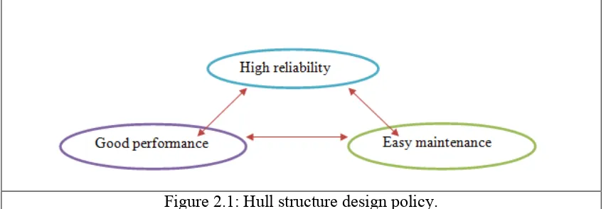
2.1.1 Hull Structure Design Policy
5 good balance of those three elements a rational design must be develop based on theoretical approach and plentiful experience. (Yasuhisa Okumoto, 2008).
Figure 2.1: Hull structure design policy.
2.1.2 Basic Idea of Hull Structure Design
A ship will break when the load applied is bigger than the ships strength, when a failure such as crack, buckling and collapse happen at a ship; it is regarded as a good chance to gain engineering knowledge, though the damage is not pleasing in itself:
(a) To go the spot on board
(b) To see the appearance of the failure
(c) To consider the phenomenon at the locality
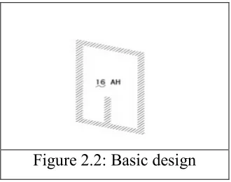
6 2.1.3 Design Flow
The design of a hull structure is generally carried out in three stages that is:
(a) Basic design
(i) Following the purpose of a previous structural arrangement in the project step, the mid ship part drawing are ready, followed by the rule-based calculations, strength, and wavering calculation, and hull steel weight estimate.
(ii) Rough shape of boundaries, plate thickness, materials, outline of slot, arrangement of web stiffeners.
Figure 2.2: Basic design
(b) Detail design
(i) Following the accomplishment of the detailed mid ship part drawing, which also contain the production process: the bow, stern, engine room, and super structure are design in detail. These designs take into account the suitable arrangement and hull block assembly procedure.
7 Figure 2.3: Detail design
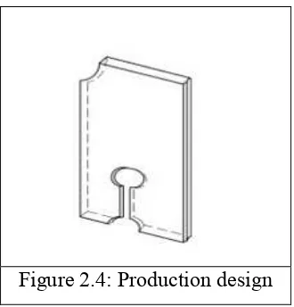
(c) Production design
(i) To the above detailed design further information for structured manufacturing is added, and all the information about the fabrication process is listed.
(ii) The 3-dimensional design is developed taking into examination of elongation to compensate for welding shrinkage, the readiness of plate edges. This is assign to the precision guide and detail work practice.
Figure 2.4: Production design
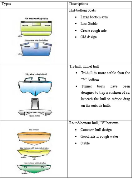
2.1.4 Boat Hull Design
8 Table 2.1: Types of hull design
Types Descriptions
Flat-bottom boats
Large bottom area
Less Stable
Create rough ride
Old design
Tri-hull, tunnel hull
Tri-hull is more stable than the “V”-bottom
Tunnel boats have been designed to trap a cushion of air beneath the hull to reduce drag on the outside hulls.
Round-bottom hull, ”V” bottoms
Common hull design
Good ride in rough water
9 2.1.5 Gross Tonnage Formulation (Twin Hull Vessels)
According to Coast Guard Marine Safety Center Tonnage Division (2004) the basic simplified tonnage formula for gross register tons of a twin hull vessel is :
Where, Gross Tonnage Formulation (GRT), Hull Volume = S x K x L x B1 x D, Deckhouse Volume = Ls x Bs x Ds
Figure 2.5: D and B1
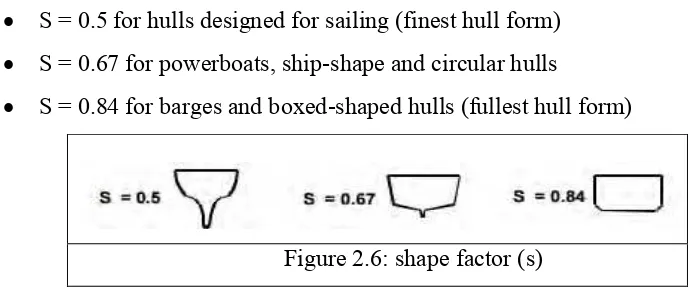
The shape factor (S) is as follows:
S = 0.5 for hulls designed for sailing (finest hull form)
S = 0.67 for powerboats, ship-shape and circular hulls
S = 0.84 for barges and boxed-shaped hulls (fullest hull form)
Figure 2.6: shape factor (s)
The keel factor (K) is as follows:
(a) K = 1.0 for all hull configuration except those designed for sailing wherein the Overall Depth includes the keel
(b) K = 0.75 for hulls designed for sailing wherein the Overall Depth includes the keel