UNIVERSITI TEKNIKAL MALAYSIA MELAKA
DEVELOPMENT OF A PROTOTYPE FOR SOLAR POWERED
SMART WATER WASTE UNIT (MACHINE ELEMENTS)
This report is submitted in accordance with the requirement of Universiti Teknikal Malaysia Melaka (UTeM) for the Bachelor of Manufacturing Engineering
Technology (Product Design) with Honours
by
NG SHEA CHEING B071210466 920130-10-5591
________________________________ ________________________________
UNIVERSITI TEKNIKAL MALAYSIA MELAKA
BORANG PENGESAHAN STATUS LAPORAN PROJEK SARJANA MUDA
TAJUK: Development of a Prototype for Solar Powered Smart Water Waste Unit (Machine Elements)
SESI PENGAJIAN: 2015/16 Semester 1
Saya NG SHEA CHEING
mengaku membenarkan Laporan PSM ini disimpan di Perpustakaan Universiti Teknikal Malaysia Melaka (UTeM) dengan syarat-syarat kegunaan seperti berikut:
1. Laporan PSM adalah hak milik Universiti Teknikal Malaysia Melaka dan penulis. 2. Perpustakaan Universiti Teknikal Malaysia Melaka dibenarkan membuat salinan
untuk tujuan pengajian sahaja dengan izin penulis.
3. Perpustakaan dibenarkan membuat salinan laporan PSM ini sebagai bahan pertukaran antara institusi pengajian tinggi.
4. **Sila tandakan ( )
SULIT
TERHAD
TIDAK TERHAD
(Mengandungi maklumat yang berdarjah keselamatan atau kepentingan Malaysia sebagaimana yang termaktub dalam AKTA RAHSIA RASMI 1972)
(Mengandungi maklumat TERHAD yang telah ditentukan oleh organisasi/badan di mana penyelidikan dijalankan)
Alamat Tetap:
iv
DECLARATION
I hereby, declared this report entitled “Development of a Prototype for Solar
Powered Smart Water Waste Unit (Machine Elements)” is the results of my own
research except as cited in references.
Signature : ………
Name : Ng Shea Cheing
v
APPROVAL
This report is submitted to the Faculty of Engineering Technology of UTeM as a partial fulfillment of the requirements for the Bachelor of Manufacturing Engineering Technology (Product Design) with Honours. The member of the supervisory is as follow:
vi
ABSTRACT
vii
ABSTRAK
viii
DEDICATIONS
To my beloved family, my mother especially.
ix
ACKNOWLEDGMENTS
First and foremost, I would like to express my gratitude towards my project supervisor, Madam Umi Hayati for the opportunity given to me to be involved in this project. Without the chance, I will never come to where I am right now. During the project period, your guidance had shine my path and made the journey much easier. Without you pointing out my mistakes and suggesting ways to further improve my project, the project would never have reached this height and depth. For that I am extremely grateful.
To my family members, nothing is comparable to the amount of support that you all have shown to me. Other than the care from all these years, you all have shown even more understanding towards me especially in my trying times. Not only that I wanted to thank you all, I would also like to tell you all that I love you all and I would not ask for anything more.
x
TABLE OF CONTENTS
DECLARATION ... iv
APPROVAL ... v
ABSTRACT ... vi
ABSTRAK ... vii
DEDICATIONS ... viii
ACKNOWLEDGMENTS ... ix
TABLE OF CONTENTS ... x
LIST OF FIGURES ... xiii
LIST OF TABLE ... xiv
LIST OF SYMBOLS AND ABBREVIATIONS ... xv
CHAPTER 1 ... 1
1.0 Introduction ... 1
1.1 Background ... 1
1.2 Objective ... 2
1.3 Problem Statement ... 2
1.4 Scope ... 3
CHAPTER 2 ... 4
2.0 Introduction ... 4
2.1 Water Wheel ... 4
xi
2.2 Conveyor ... 8
2.2.1 Types of Conveyor ... 9
2.2.2 Conveyor Design Criteria ... 12
2.3 Machine Elements ... 13
2.3.1 Gears ... 13
2.3.2 Flexible Machine Element ... 16
2.3.3 Shaft ... 17
2.3.4 Bearing ... 18
2.4 Machine Design ... 21
2.4.1 Safety... 21
2.4.2 Reliability ... 24
2.5 Machine of Similar Operation ... 25
CHAPTER 3 ... 27
3.0 Introduction ... 27
3.1 Project Planning ... 27
3.2 Process Flow ... 27
3.2.1 Literature Review & Research ... 28
3.2.2 Concept Sketch... 29
3.2.3 Selection of Machine Elements ... 30
3.2.4 Generate CAD Drawings ... 30
3.2.5 Simulate CAE Analysis ... 31
xii
3.3 Data Collection ... 32
CHAPTER 4 ... 36
4.0 Introduction ... 36
4.1 Design Sketches ... 36
4.2 Calculations for Structure ... 38
4.3 Detailed Design ... 41
4.4 Calculation for Machine Elements ... 47
4.5 Prototype ... 49
4.6 Design Simulation ... 51
4.7 Machine Safety Analysis ... 54
4.8 Discussion ... 56
4.8.1 Structural Simulation ... 57
4.8.2 Preliminary Hazard Analysis Results... 59
CHAPTER 5 ... 60
5.0 Introduction ... 60
5.1 Summary of Conclusion ... 60
5.2 Suggestion for Future Work ... 60
APPENDIX A ... 63
APPENDIX B ... 65
APPENDIX C ... 67
APPENDIX D ... 77
APPENDIX E ... 79
xiii
LIST OF FIGURES
Figure 2.1: Poncelet Water Wheel ... 8
Figure 2.2: Standard Belt Conveyor Parts... 9
Figure 2.3: Cleated Belt Conveyor... 10
Figure 2.4: Throughed Belt Conveyor ... 10
Figure 2.5: Static Roller Conveyor ... 11
Figure 2.6: Static Wheel Conveyor ... 11
Figure 2.7: Flexible Wheel Conveyor ... 11
Figure 2.8: Roller Conveyor Gate ... 11
Figure 2.9: Vibrating Conveyor ... 12
Figure 2.10: Bucket Conveyor ... 12
Figure 2.11: Screw Conveyor ... 12
Figure 2.12: Standard Spur Gear Geometries ... 14
Figure 2.13: Standards Structure ... 22
Figure 2.14: Risk Assessment Flowchart ... 24
Figure 3.1: Project Flowchart ... 28
Figure 3.2: Topography of Sungai Melaka ... 32
Figure 3.3: Sungai Melaka Phase 2 project coverage ... 33
Figure 3.4: Trash Collection Boat by PPSPM ... 33
Figure 3.5: Grundfos Unilift KP 250A ... 35
Figure 3.6: 4-footer roll-on roll-off dumpster ... 35
Figure 4.1: Design Sketches ... 37
Figure 4.2: Examples of Design Modifications for Structure ... 58
xiv
LIST OF TABLE
Table 2.1: Types of Water Wheel and its Description ... 5
Table 2.2: Water Wheel Calculation Formulas ... 6
Table 2.3: Types of Gears and Its Description ... 13
Table 2.4: Gear Parameter Calculation Formula... 14
Table 2.5: Comparison of Power Transmission Devices ... 16
Table 2.6: Belt and Chain Drive Parameter Calculations ... 17
Table 2.7: Types of Rolling Element Bearings and Their Description ... 19
Table 2.8: Examples of Related Machine Safety Standards ... 22
Table 2.9: Risk Analysis Methods ... 23
Table 2.10: Similar Types of Machines ... 25
Table 3.1: River Flow Velocity ... 34
Table 4.1: Calculations for Structure ... 38
Table 4.2: CAD Design of Water Waste Unit... 42
Table 4.3: Bill of Materials ... 44
Table 4.4: Calculations for Machine Elements ... 47
Table 4.5: Prototype of Design ... 50
Table 4.6: Simulation Parameters and Results ... 51
Table 4.7: PHA Results ... 55
Table 4.8: Frequency and Severity Ranking ... 55
xv 2D = Two Dimension
3D = Three Dimension
ANSI = American National Standards Institute
BOR = Belt-on-Roller
CAD = Computer-Aided Design
CAE = Computer-Aided Engineering
CEN = European Community for Standardization
EM = Effective Microorganisms
FEA = Finite Element Analysis
FMECA = Failure Modes, Effects, and Criticality Analysis
FTA = Fault Tree Analysis
ISO = International Organization for Standardization
MSST = Maximum Shear Stress Theory
PHA = Preliminary Hazard Analysis
1
CHAPTER 1
INTRODUCTION
1.0 Introduction
We as humans face problems every day, and we also as humans are great problem solvers. New ways are developed every day to counter the problems that we face, and developing new machines is one of the popular methods used. Machines can overcome the physical limits of humans, carrying out task that could not be done by humans or simplifying the work. Machines need to be tailored carefully to ensure that it functions accordingly, therefore machine elements needs to be studied in detail so that we can design the most suitable elements to be used on the machine.
1.1 Background
The tourism industry is a very promising source of income for Malaysia. According to figures from Tourism Malaysia (2015), the amount of foreign tourist arrivals has been gradually increasing for the past 10 years, with the highest recorded total of 27.44 million for the year 2014. According to an article published by Utusan Online on 14th March 2015, Malacca alone had received a total of 15.4 million domestic and foreign tourists in the year 2014. Hence, the tourism industry should continue to be flourished to bring more benefit to the country, and adding more attractions or preserving the existing attractions are among the measures that can be taken.
2
Melaka River Pirate Park to further promote the tourism of Sungai Melaka.
It is clear that Sungai Melaka is significant towards the tourism of the state of Malacca. Hence it is important for the upkeep of the river to be continuously carried out to preserve the river’s condition so that the river can continue to contribute and benefit the people of Malacca.
1.2 Objective
The purpose of this research is to develop a prototype of a machine which is able to assist in the maintenance of Sungai Melaka. This machine is a solar powered Smart water waste unit and it is almost similar to the Inner Harbour Water Wheel at Baltimore City, United States of America. The development is consist of four parts; the overall structure, machine elements, solar power, and sensor system. The development goal focused in this paper is to be able to develop the machine elements as well as the mechanical operations for the water waste unit.
1.3 Problem Statement
A 140-person survey done by Er (2013) on tourists’ perspective on tourism development in Malacca shows that there are still 7.14% of the respondents think that Sungai Melaka is not well maintained whereas 22.14% of the respondents think that the shores of Sungai Melaka is not well maintained, despite the extensive efforts by local authorities such as the use of Effective Microorganisms (EM) mud balls to naturally purify the river. In another research, Manap et al. (2011) found that tourism gives a strong negative perception towards the environmental impact to the residents residing around. The main environmental impact of tourism is pollution, such that air pollution from vehicle emissions, solid waste and littering at high tourist activity areas, and also sewage pollution where wastewater pollutes rivers and seas.
3
floating trash on the river surface and removing them from the river. This water waste collecting barge aims to improve the cleanliness of the river cleaning up solid wastes, creating a cleaner environment for the tourists and even act as an attraction itself. This unit must not increase the environmental impact already suffered by the river due to tourism and it can be achieved by utilizing green technology, in line with Malacca state’s slogan: “Melaka Maju Negeriku Sayang, Negeri Bandar Teknologi Hijau”. Green technology uses natural resources without damaging or depleting them. Hence the water waste unit should just be powered by natural resources: solar power and river flow. The development of the unit needs to be able to harvest the two types of resources and utilizing them to drive the machine elements of the unit to generate desired operations.
1.4 Scope
The development of this water waste unit only focuses on its machine elements. Parts to be designed are the mechanical parts, which consist of a water wheel, conveyor, rake, and the machine elements such as gears, shafts, chains and other relevant elements for the water waste unit to carry out its functions. The machine elements will be analysed and calculations will be made to select the most suitable element type and parameters. The parts will then be assembled together in an overall design with correct arrangement and positioning, together with a frame to hold them together. A scaled down prototype with substituted materials will then be fabricated as an early sample to test out each part to ensure they function together accordingly. Other aspects of the development such as the overall structure, solar power and the sensor system will not be covered in this paper.
4
CHAPTER 2
THEORETICAL BACKGROUND
2.0 Introduction
Literature reviews are based on past works and researches done by other scholars who are published in forms of books, journals, articles and other form of publications. Their publications will be studied, and from them relevant and essential theories or methods are extracted as knowledge to be used and implemented in the project. This chapter reviews and summarize past researches related to this project, which are the water wheel, conveyor, and machine elements. The reviews on the mentioned topics generally consist of the type, design criteria, and relevant calculations and formulas for us to make the best selection.
2.1 Water Wheel
Water wheels, also known as water mills are a type of machine assembly which acts as an energy extractor. The energy extracted by water wheels is the potential energy of flowing or free-flowing water which is converted into kinetic energy in the form of the rotation of the wheel. This is achieved by using the force of the water to move the blades or buckets at the outer rim of the water wheel, creating rotation which can be transferred into other forms of movement.
2.1.1 Types of Water Wheel
5
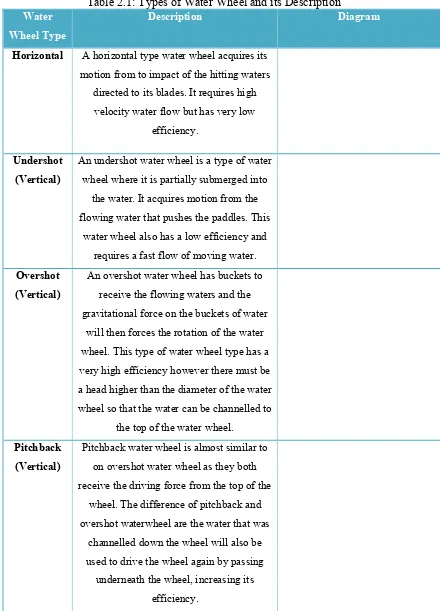
Table 2.1: Types of Water Wheel and its Description
Water Wheel Type
Description Diagram
Horizontal A horizontal type water wheel acquires its motion from to impact of the hitting waters
directed to its blades. It requires high velocity water flow but has very low
efficiency.
Undershot (Vertical)
An undershot water wheel is a type of water wheel where it is partially submerged into
the water. It acquires motion from the flowing water that pushes the paddles. This
water wheel also has a low efficiency and requires a fast flow of moving water. Overshot
(Vertical)
An overshot water wheel has buckets to receive the flowing waters and the gravitational force on the buckets of water
will then forces the rotation of the water wheel. This type of water wheel type has a very high efficiency however there must be a head higher than the diameter of the water wheel so that the water can be channelled to
the top of the water wheel. Pitchback
(Vertical)
Pitchback water wheel is almost similar to on overshot water wheel as they both receive the driving force from the top of the
wheel. The difference of pitchback and overshot waterwheel are the water that was
channelled down the wheel will also be used to drive the wheel again by passing underneath the wheel, increasing its
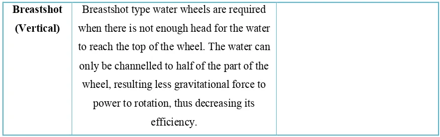
6
(Vertical) when there is not enough head for the water to reach the top of the wheel. The water can only be channelled to half of the part of the wheel, resulting less gravitational force to
power to rotation, thus decreasing its efficiency.
2.1.2 Water Wheel Design Criteria
To design a water wheel, the main criteria that needs to be considered is the head, which is the velocity of the water, the diameter of the wheel, the number of blades and their spacing, the power of the wheel and the site. A higher head is required for better efficiency as it relates to the impact force of the water hitting the blades, where higher heads means higher potential energy. The amount of potential energy can also be increased by having a larger volume of water. The diameter of the water wheel and its number of blades are determined based on the amount of head, where the head depends on the condition of the site.
For our project, the water wheel will be placed on a river; hence the type of water wheel to be used is an undershot water wheel. Table 2.2 below shows several formulas to be used in the design of the water wheel.
Table 2.2: Water Wheel Calculation Formulas
Parameter Formula Description
Head
=
=
=
The formula used is a formula for sprouting velocity, where it will translate the velocity into head, which is
the height for water to fall to reach the velocity.
Diameter of
water wheel =
= ℎ
Optimum diameter is for the diameter of the water wheel is 3 to 6 times the
7 Number of
blades =
= =
The distance between each submerged blades need to be equal to or less than
the head.
The most efficient energy transfer occurs when wheel speed is 67% to 90%
of the water speed. 67% is used to compensate slow river flow. Behrens
(1992)
The power calculated is the theoretical value. Real power of wheel can only be
acquired after knowing its efficiency rating.
Spouting velocity is the velocity of water moving vertically towards the
ground due to gravitational force.
Speed of
rotation =
Speed of rotation of wheel in terms of revolution per second.
8
Figure 2.1: Poncelet Water Wheel
2.2 Conveyor
A conveyor system is a type of material handling equipment, where it is generally used to move materials from one place to another which will minimize or even eliminate the need of manual handling. This existence of the conveyer system dates back to 1795, and was used to move grains over a short distance. (Russell, 2004) Over the years, development of conveyor systems allows them to carry heavier objects over a longer distance, and the longest conveyor by date is a total of 60 miles long used to transport phosphate at Western Sahara. Some of the major objectives of conveyor application according to McGuire (2010) are:
• Reduce actual manual handling to a minimum
• Perform all handling operations at the lowest reasonable cost
• Eliminate as many manual operations as possible
• Improve workflow between operations
• Increase throughput
9 2.2.1 Types of Conveyor
Over the years, conveyors have been developed where more types of conveyor has been made available to suit different applications. Among them, the main types of conveyors are:
1. Belt Conveyor
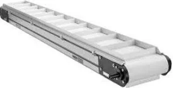
Belt conveyors as per named is a type of conveyor that uses a belt to carry materials. Belt conveyors can be used to carry a wide range of materials and is less expensive compared to other types of conveyors, hence they are the most commonly used conveyor system today. Figure 2.2 below shows the standard parts of a belt conveyor. The drive roller drives the movement of the belt whereas the tension roller acts as a counterpart in the same time ensuring the tautness of the belt. The skid pan supports the weight of the material as they are passed through the conveyor.
Figure 2.2: Standard Belt Conveyor Parts
10
Figure 2.3: Cleated Belt Conveyor
Figure 2.4: Throughed Belt Conveyor
2. Static (Gravity) Conveyor