U S E R
Username liejasa Password ●●●●●●●●●●
Remember me
Login
N O T I F I C A TI O N S View Subscribe
J O U R N A L C O N T E N T Search
Search Scope All
Search
Browse By Issue By Author By Title
F O N T S I Z E
I N F O R M A T I ON For Readers For Authors For Librarians
Journal Help
HOME ABOUT LOGIN REGISTER SEARCH CURRENT
ARCHIVES ANNOUNCEMENTS
Home > V ol 4 , N o 4 ( 2 0 1 4 )
The I nt er nat ional Jour nal of Renew able Ener gy Resear ch (IJRER) seeks to promote and disseminate knowledge of the various topics and technologies of renewable (green) energy resources. The journal aims to present to the international community important results of work in the fields of renewable energy research, development, application or design. The journal also aims to help researchers, scientists, manufacturers, institutions, world agencies, societies, etc. to keep up with new developments in theory and applications and to provide alternative energy solutions to current issues such as the greenhouse effect, sustainable and clean energy issues.
The I nt er nat ional Jour nal of Renew able Ener gy Resear ch is a quarterly published journal and operates an online submission and peer review system allowing authors to submit articles online and track their progress via its web interface. The journal aims for a publication speed of 60 days from submission until final publication.
The coverage of IJRER includes the following areas, but not limited to:
Green (Renewable) Energy Sources and Systems (GESSs) as Wind power,Hydropower, Solar Energy, Biomass, Biofuel, Geothermal Energy, Wave Energy, Tidal energy, Hydrogen & Fuel Cells, Li-ion Batteries, Capacitors
New Trends and Technologies for GESSs Policies and strategies for GESSs
Production of Energy Using Green Energy Sources Applications for GESSs
Energy Transformation from Green Energy System to Grid Novel Energy Conversion Studies for GESSs
Driving Circuits for Green Energy Systems Control Techniques for Green Energy Systems
Grid Interactive Systems Used in Hybrid Green Energy Systems Performance Analysis of Renewable Energy Systems
Hybrid GESSs
Renewable Energy Research and Applications for Industries GESSs for Electrical Vehicles and Components
Artificial Intelligence Studies in Renewable Energy Systems Computational Methods for GESSs
Machine Learning for Renewable Energy Applications GESS Design
Energy Savings
Sustainable and Clean Energy Issues
Public Awareness and Education for Renewable Energy Future Directions for GESSs
On lin e I SSN : 1 3 0 9 - 0 1 2 7
International Journal of Renewable Energy Research (IJRER) http://www.ijrer.org/ijrer/index.php/ijrer/index
I JRER is cit e d in SCOPU S
An n oun cem en ts
J ourn al Statistics
Statistics of IJRER
Year << 2014 >>
Issues published 4 Items published 113 Total submissions 707 Peer reviewed 603
Accept 131 (22%)
Decline 472 (78%)
Days to review 32 Days to publication 91
Registered users 2615 (916 new)
Registered readers 2120 (767 new)
Post ed: 2015- 01- 04
http:/ / sites.un in ova.pt/ cpe20 15
9th International Conference on Compatibility and Power Electronics
Post ed: 2014- 11- 20
Se le ct Cit e d Au t h or
Cit e d W or k
[SH OW EX PAN D ED TI TLES]
Ye a r Volu m
Aydin, E.
[Show all authors]
INT J RENEWABLE ENER 2012 2
Mahersi, E.
[Show all authors]
INT J RENEWABLE ENER 2012 2
Maruta, H.
[Show all authors]
INT J RENEWABLE ENER 2011 1
Obaidullah, M.
[Show all authors]
INT J RENEWABLE ENER 2012 2
Okedu, Kenneth E. INT J RENEWABLE ENER 2012 2
Olaofe, ZO
[Show all authors]
INT J RENEWABLE ENER 2012 2
Olaofe, ZO
[Show all authors]
INT J RENEWABLE ENER 2012 2
Roy, A INT J RENEWABLE ENER 2011 4
Salmi, T
[Show all authors]
INT J RENEWABLE ENER 2012 2
Siddiqui, R
[Show all authors]
INT J RENEWABLE ENER 2012 2
Tankari, M. A.
[Show all authors]
INT J RENEWABLE ENER 2011 1
e le ct Cit e d Au t h or
Cit e d W or k
[SH OW EX PAN D ED TI TLES]
Ye a r V olu m
Belfedhal, S.
[Show all authors]
IJRER 2011 1
International Journal of Renewable Energy Research (IJRER) http://www.ijrer.org/ijrer/index.php/ijrer/index
Mansour, Mohamed
[Show all authors]
INT J RENEWABLE ENER 2011 1
Salmi, Tarak
[Show all authors]
IJRER 2012 2
e le ct Cit e d Au t h or
Cit e d W or k
[SH OW EX PAN D ED TI TLES]
Ye a r Volu m
Aslani, A.
[Show all authors]
INT J RENEWABLE ENER 2012 2
Ben Amar, F.
[Show all authors]
INT J RENEWABLE ENER 2011 1
Ibrahim, A. INT J RENEWABLE ENER 2011 1
Se le ct Cit e d Au t h or Cit e d W or k Ye a r V olu m
Post ed: 2013- 11- 12
Com petition An n oun cem en ts 20 14
h p://www.eni.com/eni‐award/eng/bandi.shtml
Post ed: 2013- 10- 02
Coun try List of Authors
Countries
IJRER Volumes/Issues
Volume 1 Volume 2 Volume 3
1 2 3 4 1 2 3 4 1 2 3 4
India 2 3 4 8 7 10 9 11 9
Bangladesh 1 2 1 3 3 2 5 3 4
Algeria 2 1 2 3 9 4 3 2
Iran 1 3 1 1 3 4 2 1 3
Nigeria 1 1 1 2 3 2 5 5
Turkey 2 2 2 1 2 1 3 2 1
Tunusia 1 1 1 1 1 2 1 1 1 1
Malaysia 1 2 1 1 1 1
Egypt 2 2 1 1 2
Thailand 3 3 2
Japan 1 1 2 3
USA 1 1 1 2
Canada 1 1
Germany 3 1 1
South Africa 2 1 1 1
Oman 1 2 1 1
France 1 1
Italy 1 1
Ethiopia 1 3
Palestinian 1 1
Portugal 2
Kuwait 1 1
Pakistan 1 1
Indonesia 1
Tanzania 1
Tobago 2
Jordan
Australia 1
Rusia 1
U. Arab
Emirates 1
Nepal
Spain 1
Argentina 1
Belgium 1
Brasil 1
Croatia 1
Czech Republic 1
Finland 1
Hong Kong 1
Hungary 1
Israel 1
Kenya 1
Morocco 1
Oklahoma 1
Taiwan 1
United Kingdom 1
Yemen 1
Cameroon 1
Vietnam 1
Ghana Mexico Albania Mauritius Qatar
5 7 11 16 20 20 28 35 35 35 34 3
Post ed: 2014- 12- 28
Indexed Databases
http://www.doaj.org/doaj?func=findJournals&uiLanguage=en&hybrid=&query=ijrer
IJRER is indexed in SCOPUS.
Google Scholar
http://www.scimagojr.com/index.php Please visit the links below:
International Journal of Renewable Energy Research (IJRER) http://www.ijrer.org/ijrer/index.php/ijrer/index
http://www.scimagojr.com/journalsearch.php?q=International+Journal+of+Renewab http://www.scimagojr.com/journalsearch.php?q=21100258747&tip=sid&clean=0
Post ed: 2012- 11- 01
In tern ation al J ourn al of In form ation Security Scien ce
Please visit the link below for Information Security Science
http://www.ijiss.org/ijiss/index.php/ijiss
Post ed: 2012- 07- 18
Google An alytics accoun t n um ber:
UA-8476012-19
Post ed: 2011- 08- 10
More Announcements...
Vol 4, No 4 (20 14): Vol4
Table of Con ten ts
Articles
Aerodynamic Effect and Power from an Auxiliary Wind Turbine with Selected Motorcycles
Md Abdus Salam, Md Gholam Yazdani
825
Modeling and Architectural Frame Work of Off-Board V2G Integrator for Smart Grid
Santosh Kumar, Udaykumar R Yaragatti, Swapna Manasani
831
MW Level Solar Powered Combined Cycle Plant with Thermal Storage: Thermodynamic Performance Prediction
Soumitra Mukhopadhyay, Sudip Ghosh
839
Identification of Internal Parameters of a Mono-Crystalline Photovoltaic Cell Models and Experimental Ascertainment
Ferdaous Masmoudi, Fatma Ben Salem, Nabil Derbel
848
Effect of Environmental Conditions on Single and Double Diode PV system : Comparative Study
Ankit Gupta, Pawan Kumar, Rupendra Pachauri, Yogesh Kumar Chauhan
858
Smart Charging of Plug-in Electric Vehicles (PEVs) in Residential Areas: Vehicle-to-Home (V2H) and Vehicle-to-Grid (V2G) Concepts
Harun TURKER, Seddik Bacha
871
Experimental Investigation on Combustion Characteristics of DI Diesel Engine Using Diethyl Ether Fumigation with Ethanol Blended Diesel
sudhakar s, Sivaprakasam S
878
Position Control Performance Improvement of DTC-SVM for an Induction Motor: Application to Photovoltaic Panel Position
Fatma Ben Salem, Nabil Derbel
892
Study of Oscillatory Flow Heat Exchanger Used in Hybrid Solar System Fitted With Fixed Reflectors
VISHNU NARAYAN PALASKAR, SURESH PANDURANG DESHMUKH
900
Hourly Performance Prediction of Solar Ejector-Absorption Refrigeration Based on Exergy and Exergoeconomic Concept
Fateme Ahmadi Boyaghchi, Reihaneh Taheri
911
Mohd Zamri Ibrahim, Yong Kim Hwang, Marzuki Ismail, Aliashim Albani
923
Determination of Optimum Fixed and Adjustable Tilt Angles for Solar Collectors by Using Typical Meteorological Year Data for Turkey
Yohannes Berhane Gebremedhen
928
Numerical Analysis of Effect of Pitch Angle on a Small Scale Vertical Axis Wind Turbine
Bose Sumantraa R., Chandramouli S., Premsai T. P., Prithviraj P., Vivek Mugundhan, Ratna Kishore Velamati
935
Optimal Sizing of Hybrid Energy System Using Ant Colony Optimization
payal suhane
942
Heat Rate Enhancement of IGCC Power Plant Coupled with Solar thermal power plant
Rasesh R Kotdawala, Jyothi V., Gaurav Kanaujia, Bharath Adapa
948
Modeling and Simulation of Grid Inverter in Grid-Connected Photovoltaic System
Atiqah Hamizah binti Mohd Nordin, Ahmad Maliki bin Omar, Hedzlin binti Zainuddin
957
Back Surface Recombination Effect on the Ultra-Thin CIGS Solar Cells by SCAPS
Naima TOUAFEK, R. Mahamadi
964
Wind Power Assessment and Site Matching of Wind Turbines in Lootak of Zabol
Kiana Rahmani, Alibakhsh Kasaeian, Mahdi Fakoor, Amirreza Kosari, Sayyedbenyamin Alavi
976
Designing of a Small Scale Vertical Axis Wind Turbine & Its Performance Analysis in Respect of Bangladesh
Sanjib Kumar Nandi
985
Modeling Components of Solar Street Light
Mohammad Ziaur Rahman, Nafisa Saraker, Afif Nazim
991
Performance Evaluation of Sugarcane Stripper for Trash Recovery sidrah ashfaq
997
Multi-Level Wind Turbine Inverter to Provide Grid Ancillary Support Adel M. Nasiri, Yogesh Patel
1008
Study the With Different Precursor Molarities the Calculation the Urbach Energy in the Undoped ZnO Thin Films
said benramache
1012
An Alternative Model of Overshot Waterwheel Based on a Tracking Nozzle Angle Technique for Hydropower Converter
Lie Jasa, Ardyono Priyadi, Mauridhi Hery Purnomo
1019
New Location Selection Criterions for Solar PV Power Plant SUPRAVA CHAKRABORTY, PRADIP KUMAR SADHU, NITAI PAL
1030
Dynamic Demand Balancing Using DSM Techniques in a Grid-Connected Hybrid System
Ben Christopher
1041
A Study on Wind and Solar Energy Potentials in Malaysia Muhamad Mansor
1048
Development of a Microcontroller Based PV Emulator With Current Controlled DC/DC Buck Converter
Chouki Balakishan, Sandeep Babu
1055
Statistical Modelling of Wind Speed Data for Mauritius asma zaynah dhunny, Roddy Michel Lollchund, Ravindra Boojhawon, Soonil D.D.V. Rughooputh
1064
Pitch Control of Wind Turbines Using IT2FL Controller Versus T1FL Controller
Behzad Bahraminejad, Mohammad Reza Iranpour, Ehsan Esfandiari
1077
Energy Characteristics of Five Indigenous Tree Species at Kitulangalo Forest Reserve in Morogoro, Tanzania.
Christopher Thomas Warburg, Cecil Kithongo King'ondu
1084
Investigation of Some Parameters Which Affects into the Efficiency PDF
International Journal of Renewable Energy Research (IJRER) http://www.ijrer.org/ijrer/index.php/ijrer/index
of Quantum Dot Intermediate Band Solar Cell Abou El-Maaty M Aly
1093
A Comprehensive Study on Microgrid Technology
Ramazan Bayindir, Eklas Hossain, Ersan Kabalci, Ronald Perez
1107
Multiplier Effects on Socioeconomic Development from Investment in Renewable Energy Projects in Egypt: DESERTEC Versus Energy for Local Consumption Scenarios
Noran Mohamed Farag, Nadejda Komendantova
1118
Optimization of Parameters for Purification of Jatropha Curcas Based Biodiesel Using Organic Adsorbents
sangita Banga, Pradeep K Varshney, Naveen Kumar, Madan Pal
1125
Online ISSN: 1309-0127
www.ijrer.org
U S ER
Username liejasa Password ●●●●●●●●●●
Remember me
Login
N OT IFI CA T ION S View
Subscribe
J O U R N AL C ON TE NT Search
Search Scope All
Search
Browse By Issue By Author By Title
FO NT SI ZE
INF ORM A T ION For Readers For Authors For Librarians
Journal Help
20 14
Vol 4, No 4 (20 14): Vol4
Vol 4, No 3 (20 14): Vol4
Vol 4, No 2 (20 14): Vol4
Vol 4, No 1 (20 14): Vol4
20 13
Vol 3, No 4 (20 13): Vol3
Vol 3, No 3 (20 13): Vol3
Vol 3, No 2 (20 13): Vol3
Vol 3, No 1 (20 13): Vol3
20 12
Vol 2, No 4 (20 12): Vol2
Vol 2, No 3 (20 12): Vol2
Vol 2, No 2 (20 12): Vol2
Vol 2, No 1 (20 12): Vol2
20 11
Vol 1, No 4 (20 11): Vol1
Vol 1, No 3 (20 11): Vol1
Vol 1, No 2 (20 11): Vol1
Vol 1, No 1 (20 11): Vol1
HOME ABOUT LOGIN REGISTER SEARCH CURRENT
ARCHIVES ANNOUNCEMENTS
Home > Ar ch iv e s
Archives http://www.ijrer.org/index.php/ijrer/issue/archive
U S ER
Username liejasa Password ●●●●●●●●●●
Remember me
Login
N OT IFI CA T ION S View
Subscribe
J O U R N AL C ON TE NT Search
Search Scope All
Search
Browse By Issue By Author By Title
FO NT SI ZE
INF ORM A T ION For Readers For Authors For Librarians
Journal Help
HOME ABOUT LOGIN REGISTER SEARCH CURRENT
ARCHIVES ANNOUNCEMENTS
Home > Archives > V ol 4 , N o 4 ( 2 0 1 4 )
Vol4
Table of Con ten ts
Articles
Aerodynamic Effect and Power from an Auxiliary Wind Turbine with Selected Motorcycles
Md Abdus Salam, Md Gholam Yazdani
PDF 825
Modeling and Architectural Frame Work of Off-Board V2G Integrator for Smart Grid
Santosh Kumar, Udaykumar R Yaragatti, Swapna Manasani
PDF 831
MW Level Solar Powered Combined Cycle Plant with Thermal Storage: Thermodynamic Performance Prediction
Soumitra Mukhopadhyay, Sudip Ghosh
PDF 839
Identification of Internal Parameters of a Mono-Crystalline Photovoltaic Cell Models and Experimental Ascertainment
Ferdaous Masmoudi, Fatma Ben Salem, Nabil Derbel
PDF 848
Effect of Environmental Conditions on Single and Double Diode PV system : Comparative Study
Ankit Gupta, Pawan Kumar, Rupendra Pachauri, Yogesh Kumar Chauhan
PDF 858
Smart Charging of Plug-in Electric Vehicles (PEVs) in Residential Areas: Vehicle-to-Home (V2H) and Vehicle-to-Grid (V2G) Concepts
Harun TURKER, Seddik Bacha
PDF 871
Experimental Investigation on Combustion Characteristics of DI Diesel Engine Using Diethyl Ether Fumigation with Ethanol Blended Diesel
sudhakar s, Sivaprakasam S
PDF 878
Position Control Performance Improvement of DTC-SVM for an Induction Motor: Application to Photovoltaic Panel Position
Fatma Ben Salem, Nabil Derbel
PDF 892
Study of Oscillatory Flow Heat Exchanger Used in Hybrid Solar System Fitted With Fixed Reflectors
VISHNU NARAYAN PALASKAR, SURESH PANDURANG DESHMUKH
PDF 900
Hourly Performance Prediction of Solar Ejector-Absorption Refrigeration Based on Exergy and Exergoeconomic Concept
Fateme Ahmadi Boyaghchi, Reihaneh Taheri
Wind Speed Modeling for Malaysia
Mohd Zamri Ibrahim, Yong Kim Hwang, Marzuki Ismail, Aliashim Albani
PDF 923
Determination of Optimum Fixed and Adjustable Tilt Angles for Solar Collectors by Using Typical Meteorological Year Data for Turkey
Yohannes Berhane Gebremedhen
PDF 928
Numerical Analysis of Effect of Pitch Angle on a Small Scale Vertical Axis Wind Turbine
Bose Sumantraa R., Chandramouli S., Premsai T. P., Prithviraj P., Vivek Mugundhan, Ratna Kishore Velamati
PDF 935
Optimal Sizing of Hybrid Energy System Using Ant Colony Optimization
payal suhane
PDF 942
Heat Rate Enhancement of IGCC Power Plant Coupled with Solar thermal power plant
Rasesh R Kotdawala, Jyothi V., Gaurav Kanaujia, Bharath Adapa
PDF 948
Modeling and Simulation of Grid Inverter in Grid-Connected Photovoltaic System
Atiqah Hamizah binti Mohd Nordin, Ahmad Maliki bin Omar, Hedzlin binti Zainuddin
PDF 957
Back Surface Recombination Effect on the Ultra-Thin CIGS Solar Cells by SCAPS
Naima TOUAFEK, R. Mahamadi
PDF 964
Wind Power Assessment and Site Matching of Wind Turbines in Lootak of Zabol
Kiana Rahmani, Alibakhsh Kasaeian, Mahdi Fakoor, Amirreza Kosari, Sayyedbenyamin Alavi
PDF 976
Designing of a Small Scale Vertical Axis Wind Turbine & Its Performance Analysis in Respect of Bangladesh
Sanjib Kumar Nandi
PDF 985
Modeling Components of Solar Street Light
Mohammad Ziaur Rahman, Nafisa Saraker, Afif Nazim
PDF 991
Performance Evaluation of Sugarcane Stripper for Trash Recovery
sidrah ashfaq
PDF 997
Multi-Level Wind Turbine Inverter to Provide Grid Ancillary Support
Adel M. Nasiri, Yogesh Patel
PDF 1008
Study the With Different Precursor Molarities the Calculation the Urbach Energy in the Undoped ZnO Thin Films
said benramache
PDF 1012
An Alternative Model of Overshot Waterwheel Based on a Tracking Nozzle Angle Technique for Hydropower Converter
Lie Jasa, Ardyono Priyadi, Mauridhi Hery Purnomo
PDF 1019
New Location Selection Criterions for Solar PV Power Plant SUPRAVA CHAKRABORTY, PRADIP KUMAR SADHU, NITAI PAL
PDF 1030
Dynamic Demand Balancing Using DSM Techniques in a Grid-Connected Hybrid System
Ben Christopher
PDF 1041
A Study on Wind and Solar Energy Potentials in Malaysia Muhamad Mansor
PDF 1048
Development of a Microcontroller Based PV Emulator With Current Controlled DC/DC Buck Converter
Chouki Balakishan, Sandeep Babu
PDF 1055
Statistical Modelling of Wind Speed Data for Mauritius asma zaynah dhunny, Roddy Michel Lollchund, Ravindra Boojhawon, Soonil D.D.V. Rughooputh
PDF 1064
Vol 4, No 4 (2014) http://www.ijrer.org/index.php/ijrer/issue/view/4785074604081163
Pitch Control of Wind Turbines Using IT2FL Controller Versus T1FL Controller
Behzad Bahraminejad, Mohammad Reza Iranpour, Ehsan Esfandiari
PDF 1077
Energy Characteristics of Five Indigenous Tree Species at Kitulangalo Forest Reserve in Morogoro, Tanzania.
Christopher Thomas Warburg, Cecil Kithongo King'ondu
PDF 1084
Investigation of Some Parameters Which Affects into the Efficiency of Quantum Dot Intermediate Band Solar Cell
Abou El-Maaty M Aly
PDF 1093
A Comprehensive Study on Microgrid Technology
Ramazan Bayindir, Eklas Hossain, Ersan Kabalci, Ronald Perez
PDF 1107
Multiplier Effects on Socioeconomic Development from
Investment in Renewable Energy Projects in Egypt: DESERTEC Versus Energy for Local Consumption Scenarios
Noran Mohamed Farag, Nadejda Komendantova
PDF 1118
Optimization of Parameters for Purification of Jatropha Curcas Based Biodiesel Using Organic Adsorbents
sangita Banga, Pradeep K Varshney, Naveen Kumar, Madan Pal
PDF 1125
Online ISSN: 1309-0127
www.ijrer.org
INTERNATIONAL JOURNAL of RENEWABLE ENERGY RESEARCH Jasa et al., Vol.4, No.4, 2014
An Alternative Model of Overshot Waterwheel
Based on a Tracking Nozzle Angle Technique for
Hydropower Converter
Lie Jasa*
’
**, Ardyono Priyadi**, Mauridhi Hery Purnomo**
‡
*Department of Electrical Engineering, Faculty of Engineering, Udayana University, Denpasar, Bali, Indonesia **Department of Electrical Engineering, Faculty of Technology Industry, Sepuluh Nopember Institute of Technology,
Surabaya, Indonesia
([email protected], [email protected], [email protected])
‡Corresponding Author; Mauridhi Hery Purnomo, Department of Electrical Engineering, Kampus ITS Sukolilo, Surabaya
60111, Indonesia, Tel: +62 31 594 7302, Fax: +62 31 593 1237, [email protected]
Received: 25.09.2014 Accepted: 09.11.2014
Abstract- The efficiency of a waterwheel is a measure of its capacity to convert the kinetic energy of flowing water into
mechanical energy. The rotation of a waterwheel is influenced by several parameters including blade shape, number of blades, nozzle angle, and rim diameter. This study focuses on finding the parameters that influence the rotations per minute (RPM) of the waterwheel. The research method involved analysis, modelling, and a validation step. The results show that the triangular blade was an improvement over previous research on waterwheels with propeller blades. Our experiments produced 5,73 higher
efficiency than a vane having a nozzle angle of 20°.
Keywords- Waterwheel, RPM, blade, nozzle.
1.
Introduction
Global warming is a great concern to Indonesian people[1]. More sustainable practices require the use of clean energy sources. Achieving sustainable energy use requires everyone to use energy wisely, and in a way friendly to the environment. The developments of renewable energy sources are necessary[2] because: (a) oil prices are unstable and (b) mineral-based energy reserves are limited.
Hydroelectricity is an important component of the world’s
renewable energy supply. In 2011, hydroelectricity accounted for 15% of the world electricity production[3],[4] Among all renewable energy sources, water has the lowest cost and is the most reliable resource. Micro-hydro is popular because of its simple design, easy operation, and inexpensive installation[5]. Recent research of micro-hydro used a waterwheel in Dusun Gambuk Pupuan Tabanan Bali, Indonesia[6],[7],[8] to produce only 0,7 kW of energy. It is possible that the waterwheel was inefficient because it was unable to convert the maximum amount of water energy. The parameters of the waterwheel included a head of 17 m, a water discharge of 40 L/sec, 23–26 rotations per minute (RPM), and a diameter of 200 Cm, which should produce more than 0,7 kW[9].
Hydropower systems are classified, in accordance with their installation capacities, as large, medium-size, small, and micro[10]. Micro-hydro systems generally have a generating capacity of less than 100 kW. The capacity of power generation is determined by the ability of the waterwheel to
convert the water’s kinetic energy into mechanical energy.
Physicists generally describe waterwheels as analogous to physical, biological systems[11],[12],[13],[14]. Flowing water flow has a capacity of energy, and the waterwheel converts the kinetic energy of flowing water to generate electricity. This study focuses on finding the parameters of the waterwheel to produce a maximum RPM.
Research on hydropower converters show that some parameters of the waterwheel design have great impact on efficiency[15],[16]. Rotation of a waterwheel depends on the radius, blade, water discharge, volume, and nozzle angle[17] The volume of the blade is affected by gravitational force, causing the waterwheel to rotate clockwise. The speed of the waterwheel is measured in RPM, whereas the radius of the waterwheel determines the torque produced.
1014 cross-flow turbine with mathematical models, especially
looking at the flow in the space between each blade, conducted simulation of the model, made a prototype of the waterwheel, and compared efficiency with previous research. A waterwheel prototype was developed with an adjustable nozzle length, nozzle position, and nozzle angle. The highest RPM of the waterwheel is determined by adjusting these parameters.
Propeller blade design developed by Denny[15] was compared with our model. Both prototypes of the models were developed with equal diameter, blade thickness, and blade number. The purpose was to obtain real data for both models. The technical results proved that our model was able to produce higher RPM.
2.
Design Overshot Waterwheels
2.1.Previous Model
The ideal overshot waterwheel[15] model has 12 triangular buckets attached to the wheel rim. Each bucket moves freely on the horizontal axis. Buckets are filled with water that drops vertically through the channel. The water-filled bucket causes the waterwheel to spin. Low spill angles,
φ1, near the rim of the wheel cause the buckets to shed water; otherwise, no water is spilled. It was assumed that the wheel is frictionless and works by turning a millstone. The difference between the ideal waterwheels and the real waterwheels is in the mathematical analysis and physics, whereby an ideal waterwheel does not exist. First, real waterwheels did not have pivoted buckets. This design was adopted to ensure that water does not spill out as the wheel turned. Instead, the rim of the wheel is partitioned off into sections rotating with the wheel, and so the amount of water spilled out increases as the spill angle (φ) increases[15]. As the wheel turns, water also splashes over the sides into the buckets and falls from the higher buckets to lower buckets.
To make the overshot waterwheel model more realistic, Denny[15] made a number of changes. First, real waterwheels do not have pivoted buckets. Instead, the rim of the wheel is portioned off into sections, as shown in Figure 1. They rotate with the wheel, and so water spills out increasingly as φ increases. Also, water splashes over the sides as it flows into the buckets. Efficiency of overshot waterwheel model developed by Denny, as shown at equation (1)
= {1+sin(φ)} / {2 + v2/(2 g R)}
(1)
1
2
3
4
5 6 7 8
Fig.1. Overshot waterwheel with canted vanes[15]
2.2. New Model
A new design of waterwheel blade shape is changed from propeller into a triangle. The new model is compared with the previous design to show if RPM changes with the change of nozzle angle. The parameters of waterwheel include diameter, blade thickness, blade number, and length of nozzle. Water discharge was equal for all tests. The parameters of the model used were diameter = 50 cm, thickness = 10 cm, number of blades = 8, and length of nozzle = 13 cm. The design of the model can be seen in Figure 2.
The blades are attached at the edge of the wheel and installed following the line of the diameter rim. It was placed on each line in the opposite direction between the left and right side. It determines the direction of rotation of the waterwheel. Mathematical analysis of the new waterwheel model is described in more detail in section 3.
1
2
3
4
5 6 7 8
Fig.2. Design of new model waterwheels
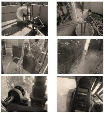
The waterwheel model is made from acrylic material and rotates clockwise when water fills the blade. Details can be seen in Figure 3. The video demonstration of this model can be accessed at You Tube [18].
INTERNATIONAL JOURNAL of RENEWABLE ENERGY RESEARCH Second Author et al., Vol.4, No.4, 2014
1015
Fig.3. Model of waterwheels simulation
3.
Mathematics Analysis of New Model
The waterwheel model is made in a standing position, and the blades are placed between two rims. The water is restrained on one-half of the blades, while the others are empty. Influence of earth gravitational force on the volume of water causes the wheel to spin on its axis. In this study, 16 triangular blades were attached on the edge of the wheel. The number of blades affects the simulation model, and is a consideration for the ease of construction. Our experience shows that if the waterwheel is inefficient, then water energy is not optimally converted to mechanical energy.
SECTOR A
SECTOR B
SECTOR C
Fig.4. Sector blade of waterwheel
Water volume of each blade is calculated depending on the position of the blades on the rim while it is in motion. It is computed by multiplying surface area by thickness of wheels. With simple mathematics, the authors split the surface area of the water on each blade into three sectors. The blades positioned on the right side of the rim were divided into three sectors, namely, A, B, and C, as in Figure 4. Sector A is at an
angle (α) between 0° and 4η° (first quadrant includes blades 1,
2, 3, and 4). In sector A, α is the angle between vertical axis with the surface line of blade positions 1, 2, 3, and 4 on the
rim. Sector B is at an angle (α) between 0° and 4η° (first quadrant includes blades η, θ, 7, and 8). In sector B, α is the
angle between the horizontal axis and the surface line of blade
positions η, θ, 7, and 8 on the rim. Sector C is an angle (α) between 0° and (−4η°) (fourth quadrant includes blades 9, 10, 11, and 12). In sector C, α is the angle between horizontal axis
with the surface line of blade positions 9, 10, 11, and 12 on the rim.
3.1. Sector A
In Figure 5, we compute the surface area of QQXRUXQ. It is obtained by computing the surface area of triangle QXR, QQN, and RRM. Further, we compute the length of the line MN, the surface area of a triangle MNX, and the area of QQRRXQ, then the surface area of a triangle RRU and the surface area of QQXRUXQ was obtained, as shown in equation (3).
R
R
Q Q
X
X
W V
U I
2
90
C
N
M
D Q
Q
X R U
X
Fig.5. Surface area of sector A
Triangle QXR is computed by the following formula
LQXR = ¼ (QR)2 tan( ) (2)
Area of RRU is computed as
LRRU =
{(PR)2 sin(½α)[cos(α)-cos(2α) sin(90-α)]/cos( -α)} (3)
Surface area of QQXRUXQ is equal to equation (3) minus equation (2); the result is shown in equation (4).
Surface area of QQXRUXQ =
A = {2sin2(½α) tan(90- )[((PR)2+(PQ)2-½ (PR+PQ)2)]}
B = {½sin(½α)(PR+PQ) QR(tan(90- )tan ( )+1)} C = {½ (QR)2 tan( )}
D = {(PR)2sin(½α)[cos(α)-cos(2α) sin(90-α)] / cos( -α)}
LQQXRUXQ = [A-B+C-D] (4)
3.2. Sector B
1016 Q
90
Q
X R R
2
T S
2
X
X R
Q T
Fig.6. Surface area of sector B
Surface area of a triangle between points QRT is computed by the formula:
LQRT = ½ (QR)2 tan(α) (5)
where the area of QXR is
LQXR = ¼ (QR)2tan( ) (6)
The surface area of TQXRT is computed with the triangles QXR and QRT, and the result is shown in equation (7)
LTQXRT = ¼ (QR)2[tan( )-2 tan(α)] (7)
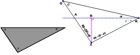
3.3. Sector C
In Figure 7, we compute the plane area of AXR, where line AR is the surface area of the water contacting the blade.
The angle BXA is represented with (β), the angle XRQ is represented with , and the angle ARQ is represented with α; therefore, the angle XRA is represented as ( ) − (α). The blade
angle of XRQ is equivalent to 180° − 2 , which makes the
blade an isosceles triangle. So, a triangle of XBR is a right
triangle, whereby the angle of BXR is 90° − ( − α).
Fig.7. Surface area of sector C
Surface triangle area of AXR is computed to use a length line of RA and a height of triangle AXR. The area of triangle AXR is shown in equation (8).
LAXR =
(QR)2{sin2( -α) tan(β)+sin( -α)cos( -α)}/(8cos2( )) (8)
4.
Result and Discussion
4.1. Volume Blade Calculation
4.1.1. Simulation result
Applying equations (4), (7), and (8), the surface area of each blade is computed using Matlab simulation. When compared with previous research results[15], this study more clearly shows the volume of each blade and inference during
blade movement at various angles (α). If the distribution of
water on each blade is known, then a moment of inertia of each blade can be calculated. This result shows the influence of water mass inside the blade that causes the waterwheel to spin.
4.1.2. Experiment result
To test the validity of equations (4), (7) and (8), we compared the calculated results with manual measurements. The process measurement is performed in the laboratory of FMIPA Chemistry ITS Surabaya using a cup of 100 ml PYREX brand IWAKI ±0.5 ml, whereby it is recorded when a cup of water enters the blade. Similar steps are completed on blades 2–12. The results of the experiment can be seen in Figure 8.
Fig.8. Relationship volume and the number of blades
4.2. Obtaining the highest RPM by experiments
4.2.1. Nozzle length
During the experiment the nozzle length was varied, and effect on the waterwheel was measured in RPM. The nozzle is made of ½-inch-diameter-PVC pipe with lengths including 3, 5, 8, 10 and 12 cm. The position of the nozzle upon the blade
was at angles (α) of 0°, 11.2η°, 22.η°, 4η°, ηθ.2η°, 67.5°,
78.75°, 90°, 101.25°, and 112.5° with the angle between blades being 11.25°. Measurement RPM of the turbine uses tachometer. It is placed on the horizontal axis of the waterwheels. The experiment shows that a shorter nozzle will result in a higher RPM. The highest RPM measurement obtained was seen when the nozzle angle position was 56.25° (blade 6) is 68.3. This is one adjustment that may increase the efficiency of the turbine.
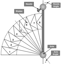
4.2.2. Nozzle angle direction
Nozzle angle (α) direction is an angle between the nozzle and a vertical axis can be seen in Figure 9. It is always higher
than the blade’s position, because water fills the blades.
0 1 2 3 4 5 6 7 8 9 10 11 12 13 14 15 16
0 200 400 600 800 1000 1200 1400
Number of blades
V
o
l[
m
l]
INTERNATIONAL JOURNAL of RENEWABLE ENERGY RESEARCH Second Author et al., Vol.4, No.4, 2014
1017 1 2 3 4 5 6 7 8
Nozzle
Angle Nozzle Blades Axle Axis Angle
Fig.9. Position of theta and alpha angle.
The process is done with a nozzle in a fixed position on the blades; the direction of the nozzle is then adjusted from an angle 0° to the angle at which water comes out of the rim (the waterwheel is not turning). The direction of the nozzle is adjusted, and then the RPM of the wheel is measured and recorded. The analysis shows that the same angle position of nozzle and blades results in greater RPM compared to a perpendicular position. The largest RPM of the waterwheels occurs when the blade angle is approximately 40.4°.
4.3. Comparison with the new model
This author makes two model waterwheels from acrylic material with equal size where one of the blades is shaped like a propeller (model A) and the other is shaped like a triangle (model B). The RPM of the waterwheels is measured with a tachometer. The RPM values are recorded at various positions (i.e., nozzle angles). Each waterwheel consists of eight blades, as compared to the mathematical analysis that evaluates waterwheels with 16 blades.
The experiment is performed at angles of 0° and the nozzle angle adjusted from 0° to 60°. The nozzle angle (α) of model A is adjusted from 0° to 25°, but the nozzle angle in model B ranges from 0° to 22.5°. The maximum RPM of model A is 158.18 with a nozzle angle of 20°. The maximum RPM of model B is 200.80 with a nozzle angle of 17.5°. This result shows that the model B waterwheel moves 35% faster than the model A waterwheel. Figure 10 shows the RPM of model A versus model B.
Fig.10. RPM of model A higher than that of model B.
The next step is to compare the RPM of model A to model B at angles of 5° and 10°. The maximum RPM of model A
was at 124.85 and 170.28 with nozzle angles of 20°. Model B RPM was 182.95 and 194.70 with angles of 17.5° and 15°. This result shows that the RPM of model A was lower than that of B by approximately 50% and 13.4%, respectively.
The same comparisons were made for an angle axis ( ) of 15°, 20°, and 40°, which resulted in model A being nearly equivalent to model B. The maximum RPM of model A was 224.52, 222.08, and 201.97, whereas the RPM of model B was 215.58, 213.58 and 204.025. Figure 11 shows the RPM of model A versus model B.
Fig.11. RPM of model A equal model B.
The same experiment for an angle axis of 35° resulted in model A being faster than model B. Maximum RPM of model A was 193.1, whereas the maximum RPM of model B was 152.68. Figure 12 shows the RPM of model A as compared to model B.
Fig.12. RPM of model A lower than that of model B
Having obtained the RPM ratio because of changes in nozzle angle and axis, we can find the value of the efficiency of the waterwheel. The value of the efficiency is calculated by comparing the output power with input power. The input power is calculated from the energy of water entering the turbine. The output power is calculated from the value of measuring currents and voltages on the generator. The results of measurements of current (I) and voltage (V), and the results of the calculation of power (P) and efficiency ( ) is shown in Table 1.
0 10 20 30 40 50 60
0 50 100 150 200 250
Theta 0 Degrees
Alpha degree R P M Model A Model B
0 10 20 30 40 50 60
0 50 100 150 200 250
Theta 15 Degrees
Alpha degree R P M Model A Model B
0 10 20 30 40 50 60
0 20 40 60 80 100 120 140 160 180 200
Theta 35 Degrees
1018
Table 1. Comparison all of angle ( ) model A and model B
Angle
( o)
Model A (Propeller) Model B (Triangle)
(η)
efficiency status Opti
mal
(αo)
I (A) V (V) P (W) η (%) RPM Max Opti mal
(αo)
I (A) V (V) P (W) η (%) RPM Max
0 22,5 0,20 2,35 0,46 14,60 131,90 22,5 0,15 1,30 0,19 6,00 81,00 A>B
5 20 0,19 2,30 0,44 13,92 133,30 22,5 0,17 1,80 0,31 9,75 106,80 A>B
10 20 0,20 2,35 0,46 14,60*) 131,10 20 0,16 1,65 0,26 8,41 95,10 A>B
15 30 0,19 2,40 0,44 14,14 132,30 20 0,18 2,40 0,44 13,91 130,90 A=B
20 20 0,19 2,30 0,43 13,70 129,20 20 0,21 2,60 0,53 16,98 138,60 A<B
25 17,5 0,19 2,25 0,42 13,26 131,10 20 0,21 2,65 0,54 17,31 141,60 A<B
30 17,5 0,19 2,40 0,46 14,53 132,40 20 0,18 2,05 0,36 11,43 117,30 A>B
35 17,5 0,18 2,10 0,37 11,71 120,60 20 0,22 2,90 0,64 20,32*) 161,70 A<B
40 17,5 0,17 1,85 0,31 10,02 107,30 20 0,21 2,80 0,57 18,28 150,80 A<B
45 17,5 0,18 2,10 0,37 11,71 121,60 20 0,18 2,35 0,43 13,70 126,00 A<B
*) Maximum of efficiency
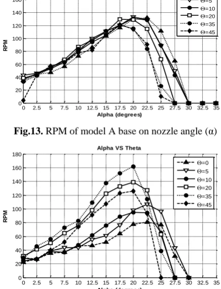
Figure 13 and Figure 14 respectively show the resulting of RPM waterwheel based on changes in nozzle angle (α) and axis angle ( ) for models A and Model B. The maximum RPM of Waterwheel triangle Model higher than the propeller model.
Fig.13. RPM of model A base on nozzle angle (α)
Fig.14. RPM of model B base on nozzle angle (α) The total extractable hydraulic power from the flowing water is given by the following expression: Pin = ρ g Q H. Where Pin is the hydraulic power input to the wheel (W), ρ is the density of water (1.000 kg/m3), g is the acceleration due to gravity (9,81 m/s2), Q is the volumetric water flow rate (0,00064 m3/s), H is the difference in line upstream and
downstream of the wheel = 0,5m. Pin is calculated (3.14 W). Pout = V I. Where Pout is power output of small generator (W), V is the measurement voltage (V) and I is the measurement current of the circuit (A). The Efficiency is following
expression: = Pout / Pin. The comparison of power output for
all axis angles between model A and B is shown in Figure 15.
Fig.15. Power output of model A versus model B
Fig.16. Efficiency of model A versus model B
The experimental results show that the maximum efficiency of model A is approximately 14.θ0 at = 10°, whereas in model B the maximum efficiency is approximately
20.32 at = 3η°. The Efficiency of model A was lower than
that of model B at = 20°, 2η°, 3η°,40°, and 4η°, but at = 0°,
0 2.5 5 7.5 10 12.5 15 17.5 20 22.5 25 27.5 30 32.5 35
0 20 40 60 80 100 120 140 160 180
Alpha VS Theta
Alpha (degrees) R P M =0 =5 =10 =20 =35 =45
0 2.5 5 7.5 10 12.5 15 17.5 20 22.5 25 27.5 30 32.5 35 0 20 40 60 80 100 120 140 160 180
Alpha VS Theta
Alpha (degrees) R P M =0 =5 =10 =20 =35 =45
0 5 10 15 20 25 30 35 40 45
0.2 0.25 0.3 0.35 0.4 0.45 0.5 0.55 0.6 0.65 Theta degree W a tt
Model A Model B
0 5 10 15 20 25 30 35 40 45
INTERNATIONAL JOURNAL of RENEWABLE ENERGY RESEARCH Second Author et al., Vol.4, No.4, 2014
1019 5°, 10°, 15°, and 30°, the RPM of model A was higher than
that of model B.
In Figure 16 is shown that the efficiency of the model A higher than model B at an angle theta 0o until 15o. At this point the water on the blades is able to optimally convert into energy. Indeed, the energy is not so great because of it resulted from the influence of the mass of water and gravity. This is evidenced when the angle theta increases, the energy produced on the wane.
5.
Conclusion
Based on the section 4.1.2 above is found that the actual volume of water attached to the waterwheel is 5.36 times the volume of the blade. The capacity of water in the waterwheel can be increased by increasing the width of the waterwheel linearly, assuming that water flow is constant.
Rotation of the waterwheel is affected by the length of nozzle, with a shorter nozzle producing higher RPM. This shows that the coefficient of the nozzle used affects the RPM. Base on the section 4.2.1 above is found that the highest RPM measurement obtained was seen when the nozzle angle position was 56.25° is 68.3.
Waterwheels with triangular blades produce higher RPM than waterwheels with propeller-type blades, because the volume of water retained in the triangular blade is higher than the volume retained by a propeller blade. The mass of water in the waterwheel produced the moment inertia and then produced higher angular velocity, which caused the waterwheel to spin faster.
Nozzle angle 20° is optimal to produce the highest efficiency for waterwheel propeller and triangle. While the optimal axis angle, found respectively for the propeller 10o and 20o triangle. With axis angle of 15o will produce the same RPM.
Acknowledgements
The authors convey their greatest gratitude to the Ministry of Culture and Education, Indonesia, which provided scholarships through the Sandwich-like program 2013 at Hiroshima University, Japan.
References
[1] T. Sakurai, H. Funato, and S. Ogasawara, “Fundamental
characteristics of test facility for micro hydroelectric
power generation system,” presented at the
International Conference on Electrical Machines and Systems, 2009. ICEMS 2009, 2009, pp. 1 –6.
[2] M. Djiteng, Pembangkitan Energi Listrik. Jakarta: Erlangga, 2005.
[3] S. Paudel, N. Linton, U. C. E. Zanke, and N. Saenger,
“Experimental investigation on the effect of channel
width on flexible rubber blade water wheel
performance,” Renew. Energy, vol. 52, pp. 1–7, Apr.
2013.
[4] A. Prayitno, A. Awaluddin, and A. Anhar, “Renewable
energy mapping at Riau Province: Promoting Energy Diversification for sustainable development (a case
study),” presented at the 2010 Proceedings of the
International Conference on Energy and Sustainable Development: Issues and Strategies (ESD), 2010, pp. 1
–4.
[5] L. Wang, D.-J. Lee, J.-H. Liu, Z.-Z. Chen, Z.-Y. Kuo, H.-Y. Jang, J.-J. You, J.-T. Tsai, M.-H. Tsai, W.-T. Lin, and Y.-J. Lee, “Installation and practical operation of the first micro hydro power system in Taiwan using irrigation water in an agriculture canal,” in 2008 IEEE Power and Energy Society General Meeting - Conversion and Delivery of Electrical Energy in the
21st Century, 2008, pp. 1 –6.
[6] L. Jasa, P. Ardana, and I. N. Setiawan, “Usaha
Mengatasi Krisis Energi Dengan Memanfaatkan Aliran Pangkung Sebagai Sumber Pembangkit Listrik Alternatif Bagi Masyarakat Dusun Gambuk –
Pupuan-Tabanan,” in Proceding Seminar Nasional Teknologi
Industri XV, ITS, Surabaya, 2011, pp. B0377–B0384.
[7] L. Jasa, A. Priyadi, and M. H. Purnomo, “Designing
angle bowl of turbine for Micro-hydro at tropical area,”
in 2012 International Conference on Condition
Monitoring and Diagnosis (CMD), Sept., pp. 882–885.
[8] L. Jasa, A. Priyadi, and M. H. Purnomo, “PID Control
for Micro-Hydro Power Plants based on Neural
Network,” 2012.
[9] L. Jasa, Renewable Energy. Youtube : Gambuk,
Pupuan, Tabanan Bali, 2011.
[10] A. Zaman and T. Khan, “Design of a Water Wheel For
a Low Head Micro Hydropower System,” Journal
Basic Science And Technology, vol. 1(3), pp. 1–6, 2012.
[11] G. Muller, Water Wheels as a Power Source. 1899. [12] C. A. Mockmore and F. Merryfield, “The Banki Water
Turbine,” Bull. Ser. No25, Feb. 1949.
[13] L. A. HAIMERL, “The Cross-Flow Turbine.”
[14] J. Senior, N. Saenger, and G. Muller, “New hydropower converters for very low-head differences,” vol. 48, no. 6, pp. 703–714, 2010.
[15] M. Denny, “The Efficiency of Overshot and Undershot
Waterwheels,” Eur. J. Phys., vol. 25, pp. 193–202,
2003.
[16] M. Hauck, A. Rumeau, I. Munteanu, A. I. Bratcu, S.
Bacha, D. Roye, and A. Hably, “A 1:1 prototype of
power generation system based upon cross-flow water
turbines,” in 2012 IEEE International Symposium on
Industrial Electronics (ISIE), 2012, pp. 1414 –1418.
[17] I. Vojtko, V. Fecova, M. Kocisko, and J.
Novak-Marcincin, “Proposal of construction and analysis of
turbine blades,” in 2012 4th IEEE International
Symposium on Logistics and Industrial Informatics
(LINDI), 2012, pp. 75 –80.
[18] L. Jasa, Model Moni Hydro. Youtube : Denpasar, Bali,