DESIGN OPTIMIZATION FOR THE ACTIVE BUMPER SYSTEM
TEST RIG
MUHAMMAD SYUKRI B. ISMAIL
“I admit that I have read this report and it has followed the scope
and quality in partial fulfillment of requirement for the degree of Bachelor of Mechanical Engineering (Automotive)
Signature : ………..
First Supervisor : Mr. Mohd Zakaria b. Mohamad Nasir
Date : ………..
Signature : ………..
Second Supervisor : Dr. Yusmady
i
DESIGN OPTIMIZATION THE ACTIVE BUMPER SYSTEM TEST RIG
MUHAMMAD SYUKRI B. ISMAIL
This report is written as a partial fulfillment of terms in achieving the awards for Bachelor of Mechanical Engineering (Automotive)
Faculty of Mechanical Engineering Universiti Teknikal Malaysia Melaka
“I admit that this report is from my own work and idea except for the summary and a
few sections which were extracted from other resources as being mention”.
Signature : ………... Writer Name : Muhammad Syukri b. Ismail
iii
To my lovely parents, my brother and sister who give me encouragement to success in my studies and not to forget special thanks to all my lecturers
ACKNOWLEDGEMENT
Firstly I would like to forward my utmost gratitude to my supervisor, En Mohd Zakaria b. Mohd Nasir because give me guideline and inducement to complete my PSM (Projek Sarjana Muda). Special thanks to En Alif Zulfakar b. Pokaad as a master student who also guide me and gave me many information to perform my project.
I would like to send my appreciation to all lab management, especially to the technicians who give corporation for me to complete my project.
v
ABSTRAK
ABSTACT
2.5 Magnetorheological (MR) Fluid 21
3.3.3 Skyhook Controller experiment 44
CHAPTER 4 RESULT AND DISCUSSION 46
4.1 CAE analysis result 47
4.1.1 Pendulum (CATIA V5R16 analysis) 47
4.1.2 Rig arm (Abaqus analysis) 51
4.2 Force & acceleration validation experiment 52
4.3 MR damper characteristic experiment 56
4.4 Skyhook controller experiment 59
CHAPTER 5 CONCLUSION AND RECOMMENDATION
5.1 Conclusion 61
5.2 Recommendation 61
REFERENCE 63
BIBLIOGRAPHY 66
ix
2.8 Deceleration, velocity, and deformation as a function of time 15
2.9 Example of Active bumper system 19
2.10 MR fluid particle diagram 22
2.11 MR fluid when subjected to magnetic field 23
2.12 Type of MR damper 23
2.13 RD-8040-1 Lord Corporation MR Damper 24
2.14 Skyhook Control illustration diagram 24
2.15 Skyhook controller Model Diagram 25
3.1 PSM Flowchart 27
Diagram
3.9 MR Damper characteristic test arrangement 42
3.10 Skyhook controller test 44
4.1 Current Pendulum result analysis 47
4.2 New pendulum design analysis 49
4.3 Rig arm analysis result 51
xi
LIST OF GRAPH
NO. TITLE PAGE
4.1 Force (N) against Time(s) 52
4.2 Acceleration (g) against Time(s) 53
4.3 Acceleration (g) against Time(s) 55
4.4 LVDT transducer reading 56
4.5 Load cell reading 57
4.6 Measured forces for five constant current levels 58 4.7 Force vs. displacement for five constant current levels 58
LIST OF TABLE
NO. TITLE PAGE
3.1 Theoretical pendulum force 40
xiii
k = Specific material stiffness
� v = Deceleration of the vehicle as function of time f(t)
� v = Velocity of the vehicle during the impact Sv = Deformation of the vehicle during the impact
∆� = Change in velocity
ζ = Damping Ratio
ωn = Natural Frequency
e = Coefficient of restitutions
A = Ampere
LIST OF APPENDIX
NO. TITTLE PAGE
A Gant Chart 68
1 software. The result data for CAE analysis then will be used to optimize the test rig. The result of test rig experiment using sensor such as accelerometer, load cell, LVDT and others is used to check the sensitivity of the sensor whether the test is suitable for the sensor reading capability and the experiment data is used to improve the design of test.
1.2 Problem Statement
1.3 Objective
To perform analysis and optimization of current test rig use in Autotronic lab for active bumper system experiment method.
1.4 Scope
1. Literature review on FEM, Crash method, Frontal crash, Active bumper system, and MR fluid.
2. Perform analysis on current test rig structure using CAE software (CATIA & ABAQUS)
3. Perform active front bumper experiment using current test rig.
4. Study and analysis disadvantages on current crash test rig in Autotronic lab. 5. Design optimization of current test rig crash.
1.5 Thesis outline
CHAPTER 1
Chapter 1 is introduction for this project. This chapter explains briefly about the project background, problem statement, objective and scope.
CHAPTER 2
3
CHAPTER 3
Chapter 3 is methodology. This chapter consists of Flowchart, Explanation, Experiment setup and procedure, Equipment, Instrumentation, Instrument setting, and Technical specification.
CHAPTER 4
Result and discussion is in chapter 4. Chapter 4 shows the result of analysis of test rig part which is previous pendulum, new pendulum, and rig arm. The experiment result and improvement of test rig is also shown in this chapter.
CHAPTER 5
CHAPTER 2
LITERATURE REVIEW
5
2.1 Finite Element Analysis
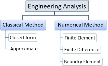
There are several methods for solving engineering problems. New mechanical design need to be analyzed before the manufacturing process to reduce the cost and failure of the design. The finite element method is one of several methods for solving engineering problems. Figure 2.1 shows method of engineering analysis.
Figure 2.1: Type of engineering analysis
Classical Method:
Closed-form solutions are available for simple problems such as bending of beams and torsion of prismatic bars
Approximate methods using series solutions to governing differential equations are used to analyze more complex structures such as plates and shells
The classical methods can only be used for structural problems with relatively simple geometry, loading, and boundary conditions.
Numerical Methods:
Boundary Element Method
Solves the governing differential equation for the problem with integral equations over the boundary of the domain. Only the boundary surface is meshed with elements.
Finite difference Method
Replaces governing differential equations and boundary conditions with corresponding algebraic finite difference equations.
Finite Element Method (FEM)
Capable of solving large complex problems with general geometry, loading, and boundary conditions.
Increasingly becoming the primary analysis tool for designers and analysts.
The finite element method is also known as the Matrix method of structural analysis is the literature because it uses matrix algebra to solve the system of simultaneous equations.
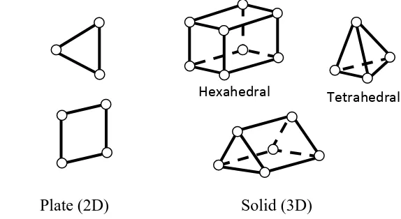
Finite elements have shapes which are relatively easy to formulate and analyze. Figure 2.2 shows three basic types of finite elements which are beams, plates, and solids.
Beam (1D) Plate (2D) Solid (3D)
Figure 2.2: Type of FEM element shape Nodes
Elements
7
The Finite element method (FEM) is a numerical approximation method. It is a method of investigating the behavior of complex structures by breaking them down into smaller, simpler pieces.
These smaller pieces of structure are called elements. The elements are connected to each other at nodes.
The assembly of elements and nodes is called a finite element model.
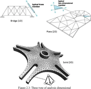
Figure 2.3: Three type of analysis dimensional (Source: www.answers.com/topic/finite-element-method)
One dimensional (1D) elements are used to model long, slender structural members, bridge and others.
Bridge (1D)
Plate (2D)
Two dimensional (2D) elements are used to model thin structural members such as thin plate, aircraft fuselage skin or car body and others.
Three dimensional (3D) solid elements are used to model thick components such as piston head, cylinder block, and others.
The finite element method approximates the behavior of continuous structure with a finite number of elements.
As one increase the number of elements (and hence, decrease the size of the elements), the results become increasingly accurate, but the computing time also increase.
The operation of Finite Element Method Basic approach
A given problem is discretized by dividing the original domain into simply shaped elements.
Elements are connected to each other by nodes.