Mairodi ST MT
Teknik Kontrol
Dosen : Mairodi, ST.,MT. Semester : Genap
SKS : 3 sks
Buku Referensi : Programmable Logic Controller, Penulis: James A. Rehg dan Glenn J. Sartori Jumlah Peserta Total : ………...
1. Pengantar Sistem Kontrol 2. Pengantar PLC
3. Field Devices 4. Hardware PLC
5. Driver Interface PLC 6. Mengkonfigurasi PLC
7. Software pemrograman PLC
8. Sistem Bilangan dan Sistem Memory dalam PLC 9. Logika Boolean dalam Pemrograman
10 Instruksi Bit 10. Instruksi Bit
11. timer dan Counter 12. Instruksi Matematika
13. Instruksi Perbandingan/comparison
2
g p
1 Pengantar Sistem Kontrol
1. Pengantar Sistem Kontrol
Loop Kontrol
Jenis Pengontrol:
¾Analog dan digital
¾On-off dan PID
Controller Process
+
Actuator
¾On off dan PID
¾Feedback, Feedforward dan Cascade Control
Sensor + Sensor + Transmitter
Tujuan Pengontrolan :
– Menjaga/mempertahankan nilai besaran pada referensi tertentu – Mengatasi gangguan/efek perubahan pada sistem
– Meningkatkan performansi sistem
Contoh-contoh pengontrol yang
Contoh contoh pengontrol yang
sering dipakai dalam industri :
•
Programmable logic controller (PLC)
Mi
t
ll
DIBAHAS DALAM KULIAH INI
•
Microcontroller
•
DCS (Distributed Control System)
•
SCADA (Supervisory Control and Data
SCADA (Supervisory Control and Data
Acquisition) System
Definition (1)
( )
•
Process
– A series of interrelated actions which transform material
It covers all resources that are involved in the process and It covers all resources that are involved in the process and talks about
process “inputs” (e.g. resources, raw material) and “outputs” (e.g.
fi i h d d t)
Raw Materials Products
Energies Out finished product)
Process
Energies Out Energies OutControl
– To maintain desired conditions in a physical system by adjusting
6
Definition (2)
( )
•
Process Control
– To maintain desired conditions in a physical system
To maintain desired conditions in a physical system
by adjusting selected variables in the system in spite
of disturbances affecting the system and observation
noise
noise
Corrective Action Process
Knowledge Data
Information
7
Daylife Example: Driving a Car
Brain:
Daylife Example: Driving a Car
• Control Objective (Setpoint):
Maintain car in proper lane Brain:
Control calculation
Eyes: Sensor
Maintain car in proper lane
• Controlled variable:
Location on the road
• Manipulated variable:
Orientation of the front wheels Orientation of the front wheels
• Actuator:
Steering wheel
• Sensor:
D i ’
Driver’s eyes • Controller: Driver • Disturbance: Steering wheel: Actuator
Curve in road
• Noise:
Rain, fog
Industrial Example #1: Heat
Exchanger
• Control Objective (Setpoint):
Maintain temperature
Product
Stream TC Steam
Maintain temperature
• Controlled variable:
Outlet temperature of product stream
• Manipulated variable:
TT
Steam flow
• Actuator:
Control valve on steam line
• Sensor:
Feed Condensate
Thermocouple on product stream
• Controller:
Temperature controller
• Disturbance:Disturbance:
Changes in the inlet feed temperature
• Noise:
Measurement noise
Industrial Example #2: Liquid
C
Level Control
• Control Objective (Setpoint):
Maintain level Maintain level
• Controlled variable:
Fluid level in the tank
• Manipulated variable:
Fluid
Fluid flow
• Actuator:
Control valve on fluid line
• Sensor:
LC
Level transmitter on the tank
• Controller:
Level controller
• Disturbance:
LC
Disturbance:
Changes in the inlet feed flow
• Noise:
Measurement noise
LT
Elements of Process Control Loop
• Sensor
Elements of Process Control Loop
Measure process variable
• Transmitter
Convert the measured process variable into standard signal Convert the measured process variable into standard signal
• Controller
Drive actuator by giving an appropriate controller output signal
A t
t
• Actuator
Adjust manipulated variable based on the value of the controller output signal
• Process
Physical system to be controlled
Istilah-istilah (I)
Istilah istilah (I)
• Control Objective (Setpoint,
SP
)
• Controlled Variable (CV) or Process Variable (
PV
)
• Measured Process Variable (
PV
m)
• Controller Output (
CO
)
• Controller Output (
CO
)
• Manipulated Variable (
MV
)
• Final Control Element (Actuator)
• Sensor/Transmitter
• Controller
• Disturbance Variable (
DV
)
• Disturbance Variable (
DV
)
• Measurement Noise
Goal of Process Operation
24 hours process operation? Hmm… I think, to achieve
Goal of Process Operation
Hmm… I think, to achieve those, we need to continuously
monitor & control the process 24 hours a day,
7 days a week!!!
• Safety & Reliability
• Product Specification
Product Specification
• Environmental Regulation
• Operating Constraint
• Operating Constraint
• Efficiency
• Maximum profit
• Maximum profit
Safety and Reliability
Safety and Reliability
• The control system must provide safe operation
Alarms, safety constraint control, start-up and shutdown
• A control system must be able to “absorb” a variety of disturbances and keep the process in a good
of disturbances and keep the process in a good operating region
Feed composition upsets, temporary loss of utilities (e g steam supply) day to night variation in the (e.g., steam supply), day to night variation in the process
Product Specification
• Quality
– Products with reduced variability
Product Specification
N C ll
– Products with reduced variability
For many cases, reduced variability products are in high demand and have high value added (e.g. feedstocks for polymers)
p u rity n tr at io n Limit p ur it y en tr atio n Limit
Old Controller New Controller
Time Im p Co n ce n Time Im p C onc e
Product certification procedures (e g ISO 9000) are
• Product certification procedures (e.g., ISO 9000) are
used to guarantee product quality and place a large
emphasis on process control
Environmental Regulation
Environmental Regulation
• Various government laws may specify that the
Various government laws may specify that the
temperatures, concentrations of chemicals,
and flow rates of the effluents from a process
p
be within certain limit
Examples:
– Regulations on the amounts of SO
2that a
process can eject to the atmosphere, and on the
lit
f
t
t
d t
i
l k
quality of water returned to a river or a lake
Operational Constraint
Operational Constraint
• All real process have constrained inherent to
All real process have constrained inherent to
their operation which should be satisfied
throughout the operation
g
p
Examples:
– Tank should not overflow or go dry
g
y
– Distillation column should not be flooded
– Catalytic reactor temperature should not exceed
y
p
an upper limit since the catalyst will be destroyed
Efficiency
Efficiency
• The operation of a
• The operation of a
process should be as
i
l
ibl
economical as possible
in utilization of raw
material, energy and
capital
p
Maximizing the Profit of a Plant (1)
Maximizing the Profit of a Plant (1)
• The operation of a process may many
p
p
y
y
times involves controlling against
constraints
Th
l
th t
bl t
• The closer that you are able to
operate to these constraints, the more
profit you can make
Example:
– Maximizing the product production rate usually involving controlling the process y g g p against one or more process constraints
Maximizing the Profit of a Plant (2)
Constraint control example: A reactor temperature control
Maximizing the Profit of a Plant (2)
• At excessively high temperatures the reactor will experience a temperature runaway and explode
• But the higher the temperature the greater the product yield
• Therefore better reactor temperature control allows safe operation at a
New Controller Improved Performance
• Therefore, better reactor temperature control allows safe operation at a higher reactor temperature and thus more profit
The History of Process Control
• 1960s Pneumatic analog instrumentation, controllers, and computing modules • 1970s Electronic analog instrumentation controllers and computing modules
The History of Process Control
• 1970s Electronic analog instrumentation, controllers, and computing modules
– Direct digital control with special algorithms programmed in main frame computer
• 1980s Electronic analog instrumentation and digital distributed control systems (DCS)
– Supervisory and model predictive control configured in special purpose computers
• 1990s Smart analog instrumentation, valves, and digital distributed control systemsg g y
– Supervisory and model predictive control configured in special purpose computers – Neural networks, online diagnostics, and expert systems in special purpose computers – Real time optimization using model libraries in special purpose computers
• 2000s Field bus based digital smart instrumentation, valves, and control systems
Digital bus takes full advantage of smartness and accuracy of instrumentation and valves – Digital bus takes full advantage of smartness and accuracy of instrumentation and valves – Some fast PID controllers such as flow and pressure go to the field transmitter or valve – Model predictive control, neural networks, online diagnostics, and expert systems are
integrated into the graphically configurable field bus based control systems and move to PCs
Common Types of Control Strategy
Common Types of Control Strategy
• Manual vs. Automatic
• Servo vs. Regulator
• Open-loop vs. Closed-loop
• Control strategies
– Feedback Control Feedforward Control – Feedforward Control – Cascade Control
• Single-Input Single-Output (SISO) vs. Input
Multi-Output (MIMO, also known as multivariable)
Manual vs Automatic
Temperature indicator
Should I adjust h l
Manual vs. Automatic
• Manual
the valve or should I run?
– Human has to adjust the MV to obtain the desired value of the PV based on observation and
i i
Emergency cooling
prior experiences
• Automatic
– The computer (or other device) – The computer (or other device)
autonomously controls the
process and may report status back to a operator
23
Regulator vs Servo
Regulator vs. Servo
• Regulatory control
Regulatory control
Servo control
– Follow constant
setpoint, overcoming
Servo control
• Follow the changing
setpoint
7.00 AM: 80 C… 8.00 AM: 70 C… 9 00 AM: 60 C
o o o
the disturbance
75.5 C… 75.3 C… 75.4 C…
o o o
9.00 AM: 60 C…
Open-loop vs Closed-loop
DV
Open loop vs. Closed loop
• Open-loop
PV CO
Process
Decisions
C t ll
p
p
– Process is controlled based on predetermined scenario
Ex.: When food is done in an
Controller
SP
oven, timers on outdoor lights
DV
PV CO
P
• Closed-loop
– The information from sensor
Decisions
Controller
Process
– The information from sensor is used to adjust the MV to obtain the desired value of the PV
Control Strategies (1)
• Feedback Control
C ti ti b d i bl (PV)
Control Strategies (1)
– Corrective action based on process variable (PV)
DV SP SP PV Feedback Controller CO Process Advantage
Requires no knowledge of the source or nature of disturbances, and minimal detailed information about how the process itself works
Disadvantage
Controller takes some corrective actions after some changes occurs in process variable PV
Control Strategies (2)
• Feedforward Control
B d th t f di t b (DV) Æ f df d t ll
Control Strategies (2)
– Based on the measurement of disturbance (DV) Æ feedforward controller can respond even before any changes occurs in PV
DV
Advantage
SP Feedforward CO PV
Controller Process
Advantage
Controller takes some corrective actions before the process output is different from the setpoint Æ theoretically, perfect disturbance rejection is possible!
Disadvantage
• Requires process model which can predict the effect of disturbance on PV • Requires process model which can predict the effect of disturbance on PV
• If there are some modeling error, feedforward control action will be erroneous (no corrective action)
• Feedforward controller can be quite complex
Control Strategies (3)
Control Strategies (3)
• Feedback/Feedforward Control
– Feedforward controller will adjust CO as soon as the DV is detected – If the feedforward action is not enough due to model error,
measurement error and etc., feedback controller will compensate the
DV
PV CO
difference
SP Feedforward/ CO PV
Feedback Controller
Process
Control Strategies (4)
Control Strategies (4)
• Cascade Control
– The disturbance DV1 arising within the inner loop are corrected by the
inner controller before it can affects the PV of the outer one Example: Control valve + positioner
DV SP DV1 Inner loop Outer loop SP PV CO Outer Feedback Controller Inner Feedback
Controller ProcessInner ProcessOuter
CO
Control Strategies (5)
Control Strategies (5)
• Feedback/Feedforward + Cascade Control
DV
Outer loop
Feedback/Feedforward + Cascade Control
SP
PV CO
Outer Feedback
C ll Inner Feedback Inner O ter
DV1
CO
Inner loop
PV CO
Controller Inner Feedback
Controller ProcessInner ProcessOuter
CO
SISO vs MIMO
SISO vs. MIMO
• Based on how many
PV
and
MV
we have in a process
DVs
SISO
MIMO
y
p
DV PV COProcess
…
…
CO Process PV…
…
Decisions
Controller
Process COs PVs
Performances of Process Control System
• Closeness to setpoint
• Short transient to one setpoint to other setpoint
1
2
y
• Short transient to one setpoint to other setpoint
• Smaller overshoot and less oscillation
• Smooth and minimum changes of variable
2
Smooth and minimum changes of variable
manipulation
• Minimum usage of raw materials and energy
Istilah-istilah (II)
• Manual control
Servo controlIstilah istilah (II)
• Automatic control
• Open-loop control
Servo control
Regulatory control
SISO control
MIMO control
• Closed-loop control
• Feedback control
f
MIMO control
Transient response
Overshoot
O ill ti
• Feedforward control
• Cascade control
Oscillation
Ringkasan
Ringkasan
• Control has to do with adjusting manipulated
Control has to do with adjusting manipulated
variables of the process to maintain controlled
variables at desired values
• All control loops have a controller, an actuator, a
process and a sensor/transmitter
process, and a sensor/transmitter
• Various controller strategies can be realized to
hi
d
i d
bj
ti
&
d
t
achieve desired process objectives & product
specifications
Pertemuan ke-2
Pe nga nt a r PLC
Pertemuan ke 2
Sasaran Pelatihan
• Mengetahui sejarah perkembangan PLC • Mengetahui pengontrolan dengan Relay • Prinsip dasar operasi PLC
Sejarah Singkat Sistem Kontrol Industri
j
g
• Proses kontinyu• Sederhana
• Sinyal elektrik analog 4-20 mA • Sistem kontrol digital
• Proses kontinyu • Lebih kompleks
• Sinyal elektrik analog 4-20 mA, FF, HART
g
• Input output terbatas • Sistem kontrol digital • Input output banyak • Algoritma pengontrol PID
Era Pneumatic Era PLC
Era DDC Era DCS
Smart Instrument FCS Electric Instrument
Tradisional Instrument
Era Pneumatic Era PLC
- Proses Diskrit S d h
• Menggantikan relay
• Sinyal digital
- Sederhana
- Sinyal pneumatic 3-15 psi - Sistem kontrol
penumatik-mekanik
- Input/output terbatas
• Sinyal elektrik 4-20mA • Sistem kontrol digital • Input/output banyak
• Sistem kontrol yang lebih
• Sinyal digital • FF network
• Direct download
p p
Direct Digital Control (DDC)
g
(
)
IBM Control Station Controller
IBM Control Station
Apple Control Station
Traditional Signal :
4 – 20 mA
1 – 5 V Instrument Card TT CV CV
Process A
TT TT TTFT LT LT LT PUMP
Process A
TT
Distributed Control System (DCS)
Contoh :
DCS
PLC
NI – FP
Hub – Switch
Contr
oller
Traditional Signal Semi-digital Signal Digital Signal
Industrial Comm : High Speed Data Exchange : HSE, DH+, FF, CAN
TT CV CV Spur Controller Digital Signal 0 mA Digitized :FF/DH+/CAN m A Spur TT TT TT
FT LT LT LT PUMP
Process A
4 – 2 4 – 20 m TTField Control System (FCS)
Computer Function :
Data logging
Supervisory Monitoring
Contoh :
NI – CAN
NI – FF
Setting Input
Programming
PLC/DCS
NI – FP
Industrial Communication Card
Contr
oller
Fully
Digital Signal Industrial Comm : High Speed Data Exchange : HSE, DH+, FF, CAN Spur TT CV CV Spur Controller Digitized :FF/DH+/CAN Spur Spur TT TT TT
FT LT LT LT PUMP
Process A
Controller
TT
Mengapa menggunakan PLC
g p
gg
• Bisa mengontrol komplet proses manufaktur
• Mencapai konsistensi dalam manufaktur
• Meningkatkan kualitas dan akurasi
B k j d l
li
k
lit/b h
• Bekerja dalam lingkungan yang sulit/bahaya
• Meningkatkan produktivitas
• Memperpendek waktu pemasaran
Memperpendek waktu pemasaran
• Menyediakan variasi produk yang lebih besar
Kemudahan dengan PLC
g
• PLC merupakan hardened industrial computer
• Sekuens kontrol PLC dengan mudah diubah dengan
pemrograman. Beberapa fungsi advance
:
• Aritmatika
• Manipulasi data
• Shift registers
• Penyimpanan dataPenyimpanan data
• Pemrograman LD menggunakan PC
• Link komunikasi dan jaringan antara PLC dan PC
Bagian-bagian PLC
g
g
• Bagian sensing • Bagian input • Controller • Programmer • Bagian outputBagian output
Pengontrolan di Masa Lalu
g
• Kelistrikan telah digunakan untuk mengontrol
g
g
• Berbasis pada relay
• Relay ini memungkinkan daya listrik men-switch on atau
off tanpa men-switch secara mekanik
Perkembangan PLC
g
• Pengembangan komputer dengan biaya rendah telah membawa kepada revolusi teknologi yaitu teknologi PLC
• Penggunaan PLC dimulai sejak tahun 1970 an dan menjadi pilihan utama dalam pengontrolan di industri manufaktur
• Keuntungan dari PLC :g
– Efektifitas biaya dalam mengontrol sistem kompleks – Fleksibel
Kemampuan komputasi untuk kontrol canggih – Kemampuan komputasi untuk kontrol canggih
Relay
y
• Relay digunakan untuk logika kontrol
• Relay adalah alat sederhana yang menggunakan medan magnetik y y g gg g untuk mengontrol switch
• Kontak yang menutup pada saat energized coil disebut normally open. Kontak yang menutup pada saat tidak ada energized coil p y g p p g disebut normally closed
Coil
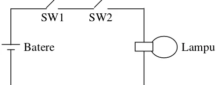
Bagaimana Mengontrol Relay ?
g
g
y
Input tunggal push button
Meng-energized coil
Mendrive output relay 220V AC
Cara Kerja Program PLC
j
g
• PLC diprogram dengan teknik berdasarkan logika skema pengkabelan
relay
• Daya listrik ada di sebelah kiri, garis vertikal, hot rail.
• Di sebelah kanan disebut neutral rail.
N t l
I t
Hot Rail
Neutral
Input
Rung Rung
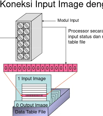
PLC Connections
I O
PUMP
nput utput
Tanki
Ketika proses dikontrol, PLC
menggunakan input dari
k
b
sensor untuk membuat
keputusan dan meng-update
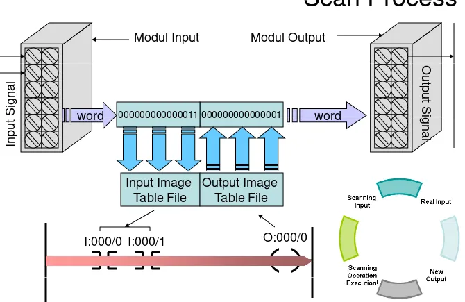
Cara Kerja CPU
j
Scanning POWER ON
Loop kontrol adalah siklus
kontinyu dari pembacaan
ScanningInput Real Input
kontinyu dari pembacaan
input PLC, memecahkan
logika LLD, kemudian
mengubah output
Scanning
Operation New
Output p
Cara Kerja PLC
Sanity Check
POWER ON
POWER ON
j
Error
STOP Yes
• Power On
• Men-check apakah hardware
bekerja dengan benar
Error
Indikator On
Scanning
Save to
bekerja dengan benar
• Jika ada masalah PLC akan
berhenti dan menyalakan indikator error No Scanning All Inputs Save to Memori
L dd
L
i S l
d
• Mulai membaca (scan) semua
input
• Ladder logic akan discan
(dipecahkan) menggunakan
Ladder Logic Solved
Scanning
( p ) gg
nilai input yang tersimpan tersebut.
• Output akan discan
• Nilai ouput berubah
Scanning All Outputs
O
C
• Nilai ouput berubah
• Waktu yang diperlukan untuk
masing-masing tahapan dalam milliseconds.
Konfigurasi Fisik PLC
g
• Fixed
– Terdiri dari prosesor, modul input-output, catu daya
dalam satu unit
Chassis adalah suatu tempat
• Modular
– Terdiri dari prosesor, semua
modul input-output sebagai Chassis adalah suatu tempat yang terdiri dari slot-slot…
… tempat modul I/O…
p p g
perangkat keras yang dapat dipasang dan dilepas secara terpisah
A Picture of PLC System
y
Man-Machine Interface Programming Device C
PLC Network
PLC PLC PLC PLC
Tipikal Panel Pengontrol (PLC)
p
g
(
)
PLC vs. PC
• PC
– Menerima masukan dari keyboard dan menampilkan hasil operasi program pada monitor
• PLC
– Menerima masukan dari suatu alat, seperti switch atau , p termokopel, dan menetapkan suatu keluaran, seperti
PLC vs. PC
• PLC didesain untuk beroperasi di lingkungan industri:
Temperatur dan kelembaban lingkungan yang fluktuatif dalam p g g y g rentang yang besar.
PLC yang didesain dengan baik tidak dipengaruhi oleh noise elektrik
elektrik.
• Hardware dan software PLC didesain sedemikian
sehingga mempermudah penggunaan oleh electrician
d
k i i
dan teknisi.
PLC diprogram dengan relay ladder logic.
PLC tampil dengan bahasa pemrograman yang dibangun dalam p g p g y g g memory permanennya,
PLC vs. PC (2)
• PC merupakan mesin komputasi yang kompleks
Mampu mengeksekusi beberapa program atau tugas secara
( )
p g p p g g
simultan dan dengan beberapa urutan
• Sedangkan PLC mengeksekusi program tunggal secara
ber r tan dan sek ensial dari instr ksi a al sampai akhir
berurutan dan sekuensial dari instruksi awal sampai akhir
• Troubleshooting dipermudah karena pada PLC sudah
didesain fault indicator/information
PLC vs. PC (3)
• Software PLC yang dijalankan pada PC
dikategorikan dalam 2 hal berikut
:
( )
dikategorikan dalam 2 hal berikut
:
Software PLC yang digunakan user untuk memprogram dan mendokumentasikan
S ft PLC di k t k it d
Typical Configurations for PLC
yp
g
Medium
Large
Small
Typical Configurations for PLC
• Small size
:yp
g
sampai 128 I/O
memory sampai 2 KB
M di
i
• Medium size
: sampai 2048 I/O
memory sampai 32 KB
• Large size
: sampai 16000 I/O
memory sampai 2 MB
Tiga tipe aplikasi PLC
Tiga tipe aplikasi PLC
• Single Ended
• Multitask
C
t l
t
• Control management
A lik i SLC 500 t ll Aplikasi SLC 500 controllers: • Packaging Machinery
• Conveyors and other Material Handling Machinery
M hi T l
• Machine Tools • Textile Machinery
• Food Products Machinery
Pertemuan ke-3
M easurem ent Variables
M easurem ent Variables
Sensors • level/volume Actuators • motors • mass • pressure • flow
AC motor DC motor
• valves
• temperature
• status
• voltage, current
block valve control valve
• relay g ,
• pH
• gas detector
• moisture
• buzzer
• etc
• valve positioner
• proximity
Field Device Im portant A spects
Field Device Im portant A spects
Range of measurement
Operating conditions
Calibration method
Dimensions p g Accuracy Precision Linearity Age Availability
Product support
Linearity
Hysteresis
Physical characteristics
Product support (maintenance)
Spare parts • temperature effects
• overpressure effects
• vibration effects
• humidity effects
• power supply effects
• load effects
Range and A ccuracy
Range and A ccuracy
y
y
Range
• Minimum and maximum value of physics quantity that canMinimum and maximum value of physics quantity that can be measured under reference operating conditions
Accuracy
• A number or quantity that defines the limit that errors will not exceed when the device is used under reference operating conditions
• example :
± 1 oF
± 1% of actual output reading
Reference Operating Conditions
Linearity
Linearity
y
y
The closeness to which a curve approximates a
straight line
(a) independent linearity (b) zero-based linearity
(a) independent linearity
(c) terminal-based linearity
linearity
(b) b d (b) zero-based
Hysteresis
Hysteresis
y
y
Hysteresis
The maximum difference for the same input between the upscale and downscale
output values during a full
t i h
range traverse in each direction
• hysteresis
Repeatability & Reproducibility
Repeatability & Reproducibility
y
y
y
y
Repeatability
The closeness of agreement b f ti among a number of consecutive measurements of the output for
• the same value of the input
• under the same operatingunder the same operating conditions
• approaching from the same direction
Reproducibility
The closeness of agreement among repeated measurements of the output for :
of the output for :
• the same value of input mode
• under the same operating
conditions over a period of time
Environm ent Conditions
Environm ent Conditions
Humidity
• Field device should be capable of operating in environments with 0-p p g 100% humidity
• Working fluid and the ambient environment should be considererd for corrosiveness
Temperature effect
• High ambient temperature on solid state electronics adversely affect component life
• Causing some electronic failures
Vibration effect
Hazardous Locations
• flammable gases or vapors
• combustible dust
A nother Im portant Factor
A nother Im portant Factor
Range adjustability
→ reduce the number of
Modular plug-in circuit
boards and easily accessible spare parts that have to be
kept on hand
Adjustable damping
test points → minimize field down-time
Interchangeable parts
Protective features
• Reverse polarity protection
• Current limiting
minimize spare parts inventory
Good local service and
g
• Lightning suppression
• Corrosive and ambient temperature control
spare parts availability
→ minimizes potential down-time
Installation consideration • Mounting flexibility
• Easy installation
Reliability based on field experience
y
Field Devices Classification
Field Devices Classification
Fieldbus
Digital Signaling
Fieldbus
HART
HART
(Highway Addressable
Remote Transducer)
Analog Signaling
Conventional Devices
Conventional Devices
Analog data (0 - 100%) is represented by analog
signal
signal
• electrical : 4-20 mA or 1-5 V
• pneumatic :
Example :
Differential pressure transmitter (0-150 psi operating
range and 4-20 mA output)
g
p )
• 4 mA → 0 psi
• 20 mA → 150 psi
psi
mA
(
150
0
)
56
.
25
4
20
4
10
10
×
−
=
Conventional Device Configuration
Conventional Device Configuration
Point-to-point
fi
ti
configuration
Requires dedicated
wiring for each
HA RT Device
HA RT Device
Interconnects smart transmitters in a two-wire
network
Simultaneous analog and digital signaling
1200 bps data rate
Shi ld d T i t d P i (2
i
l
)
Shielded Twisted Pair (2 wire loop)
Support multivariable transmitter with the use of
HART splitter
p
Can be used as either conventional transmitter or
smart transmitter
Normally not used for control caused by low data rate
HA RT Frequency Shift Keying
HA RT Frequency Shift Keying
y
y
y
y
Uses Bell202 modem
frequencies and handshakes
• ±0.5 mA variation of
conventional 4-20 mA signal
• 1200 Hz for logic 1
• 2200 Hz for logic 0
Because the average value of the FSK signal is always zero, the 4–20 mA analog signal is not affected.
The digital signal has a response time of
Simultaneous transmission of analog and digital signal
approximately 2–3 data updates per second
HA RT Point
HA RT Point-
-to
to-
-point
point
4–20 mA signal is used to communicate one process
i bl variable
Additional process variables, configuration parameters, and other device data are
other device data are transferred digitally for
• operations
• commissioning
• maintenance
• diagnostic
HA RT M ulti
HA RT M ulti-
-drop
drop
Requires only a single pair of wires and, if applicable,
safety barriers and an
auxiliary power supply for up to 15 field devices
All process values are transmitted digitally.
All field device polling
Used for supervisory control
addresses are >0
The current through each device is fixed to a minimum installations that are widely
spaced, such as pipelines, custody transfer stations, and tank farms
value (typically 4 mA).
M ulti
M ulti-
-m aster System
m aster System
y
y
Allows two masters (primary and secondary) to :
• communicate with slave devices
• provide additional operational flexibility.
Ensures interoperablility among devices through
i l d
The use of common tools for
universal commands
Enable hosts to easily access and communicate th t
products of different vendors minimizes the amount of
equipment and training
needed to maintain a plant the most common
parameters used in field devices.
HA RT A dvantages
HA RT A dvantages
Improved plant operation • Cost saving in comissioningg g
• Improved quality of measurement
• Cost saving in maintenance
Operational flexibility
Instrumentation investment protection
p
• compatibility of HART revision
• backward compatibility
• open system connection
Fieldbus Device
Fieldbus Device
Devices are configured in a 2 wire network
31 25 Kbps 1 Mbps and 2 5 Mbps data rate
31.25 Kbps, 1 Mbps, and 2.5 Mbps data rate
Analog/digital data is sent as digital signal
Data communication within devices is conformed to a
Data communication within devices is conformed to a
standard protocol (Foundation Fieldbus or Profibus)
Based on microprocessor and embedded system
t
h
l
technology
Allows point-to-point or multi-drop configuration
Simplified wiring drawings and easier control
Simplified wiring, drawings, and easier control
engineering
Inside a Fieldbus Transm itter
Inside a Fieldbus Transm itter
HARDWARE
Medium Attachment Unit (MAU) comprises the circuit needed to connect the
device to the actual bus wires
wires.
Microprocessor
A/D converter
Sensor converts the
SOFTWARE
Si l diti i
Sensor converts the physical phenomenon change into electric signal
• Conventional
Signal conditioning
Transducer block
• diagnostics
• calibration
• Silicon-based
• calibration Function block
• high/low/rate of change limits
Inside a Fieldbus Control Valve
Inside a Fieldbus Control Valve
HARDWARE
Medium Attachment Unit (MAU)
Microprocessor
D/A and A/D converter
Electric to pneumatic converter (E/P) provide
pressure signal to modulate actuator
SOFTWARE
P iti d f ti
actuator
Mechanical to electric
transducer (M/E) to monitor actuator position
Positioner and servo function
Transducer block : diagnostics and calibration
Function block
p
• high/low/rate of change limits
• control action
• fault-state mechanism
Fieldbus Devices A dvantage
Fieldbus Devices A dvantage
Reduced installation cost
• wiringwiring
• terminators
• I/O cards t l l
• control panel space
Improved quality of measurement
Distributed control design
Distributed control design
Interoperability
Online diagnostics, troubleshooting and calibration
g
,
g
P t
k 4
PLC
PLC’s
’s H a rdw a re
H a rdw a re
Pertemuan ke-4
PLC
Sa sa ra n Pe la t iha n
Sa sa ra n Pe la t iha n
Menyusun dan menggambarkan fungsi dari PLC dari
komponen-komponen hardware yang digunakan
p
p
y
g
g
Mendeskripsikan rangkaian elektrik dasar dan aplikasinya
untuk diskrit dan analog modul
Menginterprestasikan tipikal I/O dan spesifikasi CPU
Menjelaskan addresing I/O
Menggambarkan secara umum kelas dan tipe komponen
Menggambarkan secara umum kelas dan tipe komponen
memori PLC
Ba gia n I /O(1 )
Ba gia n I /O(1 )
g
g
( )
( )
Antarmuka Input dan output dianalogikan sebagai indra bagi otak PLC yaitu CPU
Bagian I/O terdiri dari I/O Chassis dan individual modul
CPU
I/O Modul di Chassis I/O Modul di Chassis
1 2 3 4 5 6 7
Power Supply
Chassis/Rack
I /O Cha ssis(1 )
I /O Cha ssis(1 )
( )
( )
AB SLC5/05 sistem 1746 merupakan sistem modular.
• Memerlukan sebuah 1746 I/O chassis untuk memuat beberapa modul.
• Chassis tersedia dalam beberapa ukuran slot modul 4, 7, 10 dan 13.
I /O Cha ssis(2 )
I /O Cha ssis(3 )
I /O Cha ssis(3 )
( )
( )
Pow e r Supply
I /O M odule a nd Cha nne l Addre ssing
I /O M odule a nd Cha nne l Addre ssing
g
g
Digunakan untuk memetakan input/output channel pada
i i d l
masing-masing module
Setiap jenis PLC dari vendor yang berbeda mempunyai k kh d l
kekhususan dalam
mengindetifikasi alamat-alamat channel di masing-masing
I nput da n Out put Addre ssing unt uk PLC SLC5 /0 5
I nput da n Out put Addre ssing unt uk PLC SLC5 /0 5
Alle n Bra dle y (1 )
Alle n Bra dle y (1 )
y ( )
y ( )
Output Input
Modul : 1 Modul : 2
O:000 O:001
I:000 I:001 Modul : 3
Modul : 4
O:002 O:003
I:002 I:003 Modul : 5
Modul : 6
O:004 O:005
I:004 I:005 Modul : 7 O:006
8 Words
I:006
I nput da n Out put Addre ssing unt uk PLC SLC5 /0 5
I nput da n Out put Addre ssing unt uk PLC SLC5 /0 5
Alle n Bra dle y (2 )
Alle n Bra dle y (2 )
y ( )
y ( )
Octal numbering system Æ PLC 5 AB
Alamat modul I:00
0 1 2 3 4 5 6 7 10 11 12 13 14 15 16 17
Alamat Channel
O:00
I nput da n Out put Addre ssing unt uk
I nput da n Out put Addre ssing unt uk
PLC SLC5 /0 5 All
B
dl
(3 )
PLC SLC5 /0 5 All
B
dl
(3 )
PLC SLC5 /0 5 Alle n Bra dle y (3 )
PLC SLC5 /0 5 Alle n Bra dle y (3 )
Decimal numbering system
Æ
PLC SLC 500 AB
Alamat modulI:00
0 1 2 3 4 5 6 7 8 9 10 11 12 13 14 15
Alamat Channel
O:00
P
L
C
S
L
C
5
0
0
A
B
A
d
d
re
s
s
in
g
F
o
rm
a
t
P
L
C
S
L
C
5
0
0
A
B
A
d
d
re
s
s
in
g
F
o
rm
a
t
gg
Address : I1: 0.1/6 I1 0 1 6 etc) etc) I=Input,e I=Input,e r /word r /word ot ot O=output, O=output, er er nt number nt number r/terminal r/terminal umber /slo umber /slo le Type (Ole Type (O
T ipik a l I nput m odul
T ipik a l I nput m odul
p
p
p
p
Status Indicator
T ipik a l Wiring I nput M odul (1 )
T ipik a l Wiring I nput M odul (1 )
p
p
g
g
p
p
( )
( )
T ipik a l Wiring I nput M odul (2 )
T ipik a l Wiring I nput M odul (2 )
p
p
g
g
p
p
( )
( )
T ipik a l Wiring I nput M odul (3 )
T ipik a l Wiring I nput M odul (3 )
p
p
g
g
p
p
( )
( )
T ipik a l Out put M odul
T ipik a l Out put M odul
p
p
p
p
Status Indicator
T ipik a l Wiring Out put M odul (1 )
T ipik a l Wiring Out put M odul (1 )
p
p
g
g
p
p
( )
( )
T Wi D i
T Wi D i
T ipik a l Wiring Out put M odul (2 )
T ipik a l Wiring Out put M odul (2 )
p
p
g
g
p
p
( )
( )
T ipik a l Wiring Out put M odul (4 )
T ipik a l Wiring Out put M odul (4 )
p
p
g
g
p
p
( )
( )
Com m on Ra t ings for Disc re t e I /O M odule
g
Input Interface :
• 24 VAC/DC 48 VAC/DC
Output Interface :
• 24 VAC/DC
• 48 VAC/DC
• 120 VAC/DC
• 230 VAC/DC
• 5 V DC(TTL Level)
• 48 VAC/DC
• 120 VAC/DC
• 230 VAC/DC
5 V DC(TTL Level)
• 5 V DC(TTL Level)
• 24 VDC
AC disc re t e I nput M odule
AC disc re t e I nput M odule
p
p
Power
T ipik a l K one k si Pe ngk a be la n M odul
T ipik a l K one k si Pe ngk a be la n M odul
I
t AC
I
t AC
I nput AC
I nput AC
Input Field Devices Input Field Devices
Switch
T ipik a l K one k si Pe ngk a be la n M odul Out put AC
T ipik a l K one k si Pe ngk a be la n M odul Out put AC
p
p
g
g
p
p
Ana log I /O M odule
Ana log I /O M odule
g
g
PLC berbasis I/O discrete hanya dapat mengendalikan
peralatan ON/OFF, keterbatasan ini berarti PLC hanya
mempunyai kontrol parsial terhadap beberapa aplikasi
kontrol proses
Analog Input modul terdiri dari rangkaian elektronik yang
g
p
g
y
g
dapat menerima sinyal analog dari peralatan lapangan.
Sinyal input ini dikonversikan dari besaran analog ke
besaran digital dengan menggunakan Analog to Digital
besaran digital dengan menggunakan Analog to Digital
Converter (ADC)
Analog Output Modulu terdiri dari rangkaian elektronik
yang dapat mengirim sinyal analog ke peralatan lapangan
yang dapat mengirim sinyal analog ke peralatan lapangan
Sinyal output ini dikonversikan dari besaran digital ke
besaran analog dengan menggunakan Digital to Analog
C
(
C)
M odul I nput Ana log
M odul I nput Ana log
p
p
g
g
Single-ended Differential Differential
Arus (0-20 mA) Tegangan (1-5 V) Tegangan (1 5 V)
I mpedansi tinggi untuk menghindari
beban sinyal
M odul Out put Ana log
M odul Out put Ana log
p
p
g
g
Isolasi antara rangkaian keluaran dan rangkaian logic dilakukan oleh
optical couplers
M odule I /O K husus
M odule I /O K husus
High Speed Counter Module
• Digunakan untuk mnyediakan interface untuk aplikasi yang g y p y g
memerlukan kecepatan counter yang tidak bisa disediakan oleh program ladder PLC. Module ini digunakan untuk menghitung pulsa dari sensor, encoder, dan switch dengan kecepatan tinggi. Dapat menghitung pulsa sampai 75 KHz
Thumb-Wheel Module
• Module ini memungkinkan penggunaan thumb-wheel switch untukModule ini memungkinkan penggunaan thumb wheel switch untuk memberikan informasi kepada PLC untuk digunakan dalam
M odule I /O K husus
M odule I /O K husus
TTL Module
• Module ini meungkinkan menstransmisikan dan menerima sinyal g y TTL untuk komunikasi dengan Processor PLC. Level sinyal TTL adalah sinyal yang dapat diterima oleh processor dan hanya butuh buffering saja
Encoder-Counter Module
• Encoder-counter module memungkinkan monitoring kontinyu pada sebuah encoder pejumlah atau encoder absolut Encoder pada sebuah encoder pejumlah atau encoder absolut. Encoder menjaga jalur posisi dari batang atau axis.
BASIC atau ASCII Module
ASCII d l ki k t k i k t i fil
• ASCII modul memunkinkan untuk mengirmkan atau menerima file ASCII. File ini biasanya program atau data yang tersusun
(manufacturing data). Modul ini biasanya diprogram dengan menggunakan bahasa BASIC
M odule I /O K husus
M odule I /O K husus
Stepper Motor Module
• Module ini menyediakan pulsa berurut ke translator Steper motor, y p p , yang memungkinkan untuk mengontrol stepper motor. Perintah untuk module dihitung oleh program pengendali di CPU
BCD Output module
BCD Output module
• Module output BCD memungkinkan sebuah PLC untuk
mengoperasikan alat yang menggunakan sinyal kode BCD seperti seven-segment display
I nt e llige nt M odule (1 )
I nt e llige nt M odule (1 )
g
g
( )
( )
Intelligent Module adalah module yang mempunyai
processor sendiri yang dapat berfungsi pararel dengan
p
y
g
p
g
p
g
PLC
PID Module
M d l P ti l I t l d D i ti di k t k
• Modul Proportional Integral and Derivative yang digunakan untuk aplikasi process control. Modul ini memungkinkan untuk
mengontrol proses diluar CPU, sehingga proses perhitungan yang rumit di CPU tidak berpengaruh terhadap perhitungan PID di
rumit di CPU tidak berpengaruh terhadap perhitungan PID di modul PID.
Servo Module
I nt e llige nt M odule (2 )
I nt e llige nt M odule (2 )
g
g
( )
( )
Communication Module
• Sebagai sistem yang terintegrasi, data harus dapat dibagi melalui g y g g , p g sistem, PLC harus dapat berkomunikasi dengan komputer,
komputer kontrol numerik (Computer Numerical Control, CNC), robot atau PLC lainnya. Modul ini memigkinkan pengguna untuk mengkoneksikan PLC ke jaringan lokal (Local Area Network, LAN), yang mungkin berbeda dengan komunikasi yang
disediakan PLC
Language Module
• Modul ini memungkinkan pengguna menuliskan program di perintah bahasa tingkat tinggi (high-level language). Dengan
p g gg ( g g g ) g
menggunakan pengubah bahasa tingkat tinggi menjadi bahasa mesin yang dipahami oleh Processor PLC. Tersedia dalam
I nt e llige nt M odule (3 )
I nt e llige nt M odule (3 )
g
g
( )
( )
Modul ini digunakan untuk mendigitasi pengejaan kata,
frase atau kalimat oleh manusia. Suara yang
y
g
terdigitalisasi disimpan dalam memori modul. Setiap kata,
frase atau kalimat diberi nomor. Ladder logic
Spe sifik a si I /O (1 )
Spe sifik a si I /O (1 )
p
p
( )
( )
Nominal Input Voltage
• Spesifikasi AC atau DC dan besarnya tegangan yang digunakan
On-State Input Voltage Range
• Nilai ini menspesifikasikan tegangan di mana input signal diidentifkasi nyala absolut (On)
Nominal Current per Input
• Nilai ini menspesifikasikan arus listrik minimum di mana peralatan mampu untuk beroperasip p
Ambient temperature rating
• Nilai ini menspesifikasikan temperatur maksimum dari udara yang menyelimuti modul I/O untuk kondisi operasi terbaik
menyelimuti modul I/O untuk kondisi operasi terbaik
Input Delay
• Juga diketahui sebagai waktu respon (respones time), nilai ini menspesifikasikan durasi waktu sinyal input yang menyala
Spe sifik a si I /O (2 )
Spe sifik a si I /O (2 )
p
p
( )
( )
Nominal Output Voltage
• Spesifikasi nilai DC atau AC yang besar dan tipe sumber p y g p tegangannya dapat dikontrol oleh output
Output Voltage Range
• Nilai ini menspesifikasikan tegangan operasi output minimum dan
• Nilai ini menspesifikasikan tegangan operasi output minimum dan maximum. Sebuah rangkain output beroperasi pada 120 V AC, mempunyai selang kerja antara 92 V AC (min) sampai 138 V AC (max)
(max)
Maximum Output Current Rating per Output and Module
CPU : PLC SLC AB
CPU : PLC SLC AB
SLC 5/01 The SLC 5/01 processors let you configure modular controllers of up to 960 I/O and a 1K- or 4K-instruction memory capacity.
SLC 5/02 The SLC 5/02 processors let you configure modular controllers of up to 4096 inputs plus 4096 outputs nominally and a 4K-instruction memory. By installing an optional scanner module into one of the 30 I/O module slots, you can add Remote I/O or DeviceNet I/O to the system. They offer 19 additional instructions, including a message instruction for initiating peer-to peer communication.
SLC 5/03 The SLC 5/03 processors let you configure modular controllers of up to 4096 inputs plus 4096 outputs and a memory of 8K or
SLC 5/03 The SLC 5/03 processors let you configure modular controllers of up to 4096 inputs plus 4096 outputs and a memory of 8K or 16K words. In addition to the features of the SLC 5/02, they have a second built-in communication port — an RS-232-C port that can be configured for ASCII or DF1 protocol, and can be configured for connection to a 1761-NET-AIC converter to provide access to a DH-485 network. SLC 5/03 processors provide bit-instruction execution times of 0.44ms and an overall system throughput of up to 10 times faster than competitive processors. Additional capabilities include: floating-point math, online programming and run-time editing, flash memory upgrades, built-in key-switch, and a built-in real-time clock and calendar.
SLC 5/04 The SLC 5/04 processors let you configure modular controllers of up to 4096 inputs plus 4096 outputs and a memory of either 16K, 32K, or 64K words. They have all the features of the SLC 5/03 processors, plus a faster communication port and shorter execution times (bit-instruction execution times of 0.37ms). Instead of a DH-485 port, the SLC 5/04 has a built-in DH+ port for communication with other SLC 5/04 and PLC processors, operator interfaces, and programming terminals. Communication via the DH+ network is three times faster than DH-485 communication.
K e y Sw it c h
K e y Sw it c h
y
y
RUN
• Mengeksekusi program ladder dan mengenergisasi output dan mengenergisasi output
• Mencegah pengguna untuk mengedit program
REM
REM
• Memungkinkan untuk mengubah mode
programmer/operator interface
RUN p g p
• Memungkinkan untuk mengedit secara online
PROG
R E M
• Program ladder tidak bisa discann/run
• Memungkinkan untuk mengedit
PROG
T ipe
T ipe --t ipe M e m ori
p
p
t ipe M e m ori
p
p
Read Only Memory (ROM)
• Memori ini didesain informasi di dalamnya hanya dapat dibaca saja dan tidak dapat diubah
tidak dapat diubah
Random Acces Memori (RAM)
• RAM sering juga disebut R/W Memori, didesain informasi di dalamnya dapat ditulis atau dibacap
• Informasi mengenai timer/counter, Input/Output Status disimpan di RAM
• Jika daya dimatikan, maka informasi dalam RAM akan ikut hilang
Programmable Read Only Memory (PROM)
• PROM informasi program di dalamnya hanya dapat dibaca, jika ada perubahan program, maka PROM dapat diganti
Erasable Programmable Read Only Memory (EPROM)
S ti PROM t t i i f i d t dih d di l
• Seperti PROM tetapi informasinya dapat dihapus dan diprogram ulang, sehingga EPROM dapat dipakai berulang-ulang
Electrically Erasable Programmable Read Only Memory (EEPROM)
• EEPROM menawarkan fleksibelitas seperti EPROM tetapi EEPROM
Progra m m ing De vic e s
Progra m m ing De vic e s
g
g
g
g
Programming Devices
Programming Devices
adalah peralatan yang
adalah peralatan yang
p
p
y
y
g
g
dapat memprogram ladder
dapat memprogram ladder
yang akan di
yang akan di--download ke
download ke
dalam CPU PLC
dalam CPU PLC
dalam CPU PLC
dalam CPU PLC
Programming devices
Programming devices
g
g
g
g
terdiri dari :
terdiri dari :
•• PCPC
•• LaptopLaptop
•• LaptopLaptop
•• Handheld UnitHandheld Unit
PLC’s Interface Driver
Pertemuan ke-5
Sasaran
Peserta mampu untuk mengkonfigurasi
protokol komunikasi PLC dengan
protokol komunikasi PLC dengan
Komunikasi Antara PLC
Komunikasi antara PLC, PLC lainnya dan remote I/O.
Komunikasi PLC dengan Komputer
g
p
Komunikasi antara Komputer dan PLC menggunakan RS Komunikasi antara Komputer dan PLC menggunakan RS
232.
Digunakan pada saat pertama kali mengakses PLC dan download parameter pada EEPROM kosong dalam
Konfigurasi PLC dengan
Programming Software
Programming Driver :
Programming Software Programming & Communication Software Driver : - RS232 - RS 485 - ENET
Modb s
Communication Driver : RS232
- Modbus
Download
Download file dari Komputer ke PLC :
ke PLC :
- Ladder Logic
- Data File Structure
- Data Table Values
DH Plus
Menghubungkan maksimum 64 perangkat per link (dianjurkan Menghubungkan maksimum 64 perangkat per link (dianjurkan
15 atau lebih sedikit node per link) PLC-5 dan SLC 5/04
KomputerKomputer
Ethernet
Menggunakan kabel UTP untuk transfer data dari dan ke PLC.
Konfigurasi PLC
g
Konfigurasi PLC merupakan penghubung antara program
PLC dan perangkat kerasnya
p
g
y
Meliputi:
– Pemilihan tipe prosesor – Pemilihan modul-modul I/O – Pemilihan media komunikasi
+ Lokasi slot
RSLinx
RSLinx merupakan aplikasi 32-bit yang memungkinkan komunikasi p p y g g pada aplikasi yang luas dan mendukung Rockwell Software serta Allen-Bradley programming, MMI, dan produk software komponen
RS Linx
RsLinx menyediakan komunikasi secara luas pada aplikasi yang meliputi:
•Produk Rockwell Software
•Produk Hardware PLC Allen-Bradley P d k MMI / HMI d h d
RSLinx
Aktifkan RSLinx :
Start>>Programs>>Rockwell Software>>RSLinx>>RSLinx
RSWho
RSWho merupakan jendela/window untuk melihat driver mana saja ktif
Konfigurasi Driver RS-232
g
Pasang kabel Serial to Parallel Converter (1774-CP10)
Konfigurasi protokol komunikasi dengan menggunakan
g
p
g
gg
driver RS-232
Dialog Box : Configure RS-232 DF1 Devices
g
g
Browsing Processor
g
Checklist
Mengkonfigurasi PLC SLC5/05
Mengkonfigurasi PLC SLC5/05
dengan RSLogix
Aktifkan RSLogix500
Membuat File Baru
1. KLIK
2. Nama processor
Setting IP Address PLC
g
2 2
1
Men-do