Investigation of Model Parameter Variation for
Tension Control of A Multi Motor Wire Winding
System
Hanafi Subari
1, Shin-Horng Chong
2, Wai-Keat Hee
2, Wen-Yee Chong
2, M.Riduwan Md Nawawi
2, Md Nazri Othman
21
Hitachi Cable (M) Sdn. Bhd, Malaysia 2
Centre for Robotic and Industrial Automation, Faculty of Electrical Engineering, Universiti Teknikal Malaysia Melaka, Hang Tuah Jaya, 76100 Durian Tunggal, Melaka,Malaysia
Abstract— Tension is the force required to pull the wire against the accumulation of all resistance, forces and loads. Tension is one of the important controlled parameters in winding process in order to determine the quality of the product. Winding process in electric discharge machine (EDM) wire manufacturing is the last process before the product is packed and sent to customers. In EDM wire manufacturing process, incorrect tension will result in wire winding failure and wire straightness failure. Since it is the last process in EDM wire manufacturing, it is needed to ensure that there is no reject product contributed in this process. The increase of the pendulum dancer fluctuation and deviation angle when the winding diameter gets bigger especially when it is in high speed will course winding tension problem. This project mainly describes about the modelling of the system and the variation parameters that affects the system performance. The system performance is validated by changing the value of radius of winder.
Keywords—tension,winding machine.
I. INTRODUCTION
Tension is force required to pull the wire against the accumulation of resistance, forces, and loads imposed on the wire as it moves, including the tension device [1]. Electrical discharge machining (EDM) is a manufacturing process whereby a desired shape is obtained using electrical discharges. EDM wire should have the same diameter and thickness where it is a major problem in industrial. Production of EDM wire is using winding and rewinding process where tension is the major parameter affecting the quality of product. In EDM wire manufacturing process, incorrect tension will result the wire winding failure and wire straightness failure. Tension control is applied in manufacturing industries such as rolling mills, yarns and cable industries.
There are two main process in producing EDM wire, which are drawing process and re-winding process. Drawing process is the process where the EDM wire is drawn from incoming supply diameter to the diameter required by the customers, while winding process is the process where the wire is re-wind from a bigger coiler to smaller spoolers specified by the customer. The wire re-winding machine is the final process of the welding wire production.
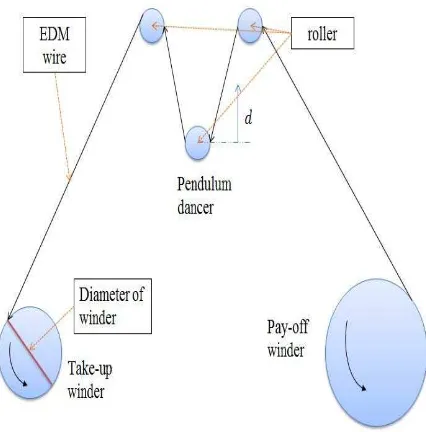
In EDM production process, the winding tension will affect the quality of welding wire. The winding diameter of pay-off winder is getting smaller as the machines runs. The pay-off winder turns faster as the diameter decreases and at the same time the winding diameter of take-up winder becomes bigger. The line speed of the take-up winder is higher and it does not match the line speed of pay-off winder. To overcome this problem, pendulum dancer plays an important role to correct the take-up winder rotation speed in order to maintain its speed and balance position. The pendulum dancer’s position must be detected quickly in order to let it return to the balance area and match the line speed of take-up winder [2].
II. WINDING MACHINE SETUP
A winding tension control system generally consists of three main parts, which is pay-off winder, processer and take-up winder. Type of take-take-up winder and pay-off winder is one of the two drive type, which are surface drive or center drive. setup since the materials are not ready.
Fig. 1. Schematic diagram of rewinding machine
Pendulum dancer is used to control tension on tension control system [4]. Commonly it is used to control the unwind tension and windup tension. The dancer is free to move up and down while exerting a constant force on the wire. If the pendulum dancer does not take a part in the system, there will be an excessive tension. The excessive tension or spikes in the tension can exceed a tensile strength of the wire and break it. It will cause the machines stop and inefficient production and scrap. Fig. 2 shows the movement of dancer system when there is tension applied to the tension control system. When there is tension, the dancer will move upwards. At the same time, potentiometer as the sensor will detect the fluctuation of dancer to check distance the dancer has moved.
Fig. 2. The movement of dancer system
III. THEORETICAL BACKGROUND
Tension control is basically functioning in closed loop according the electrical block diagram as shown in Fig. 3. A controller with high performance is required in order to manage all parameter changes, while the driver has to be responded as fast as possible during the operation. Next, the power has to be sized according to the need and performance. In the other hand, the sensor used has to be high resolution in order to get accurate data. There are three ways to sense the tension, which are direct tension measurement with load cell, indirect tension measurement with dancer arm and lastly is indirect measurement with free loop.
Fig. 3 : Block diagram of closed loop response
Dancer control techniques are commonly use in cable manufacturing machines in order to control product tension especially at intermediate and finishing cable drawing and winding processes. A displacement potentiometer is applied at the dancer and proper motor speed adjustments to measure distance moved. The displacement of the dancer is measured and compared with the reference value to obtain a correction for motor speed. By adjusting the motor speed ratios, a constant dancer position is maintained and a constant tension is achieved. Improper speed adjustment will result dancer fluctuation, leads to inconsistent and wire break. It is a difficult task to design a good dancer controller. The dancer control circuit must develop the speed reference as required to keep the dancer at set position throughout changes in motor loading, line speed and roll diameter.
The position control circuit with dancer roll and the tension control circuit with load cells have similar behavior. When the web is stretched after threading, the transition from slack to tension is smoother. For the load cell system, it requires more awareness on behalf of the operators [5].
The different models for the tension in wire winding system are based on three laws [6]:
1. Hooke’s Law, which models the elasticity of the wire;
2. Coulomb’s Law, which gives the tension variation due to friction and the contact force between wire and roller;
IV. MODELLING OF THE SYSTEM
Fig. 4 shows the sketch of wire winder system [7]. This system mainly consists of three subsystems that are winders, dancer and winder drive train where these three subsystem are sketched as shown in the Fig. 4.
where
ε = strain of the system
σ = stress in the system E = Young’s Modulus
A = area
ρ = density of undeformed material
Fig. 4. Sketch of wire winder system
The following assumptions are used during the development of the model:
1. The velocity of wire from take-up winder is constant.
2. The cross-sectional area of the system is uniform.
3. The strain is the length change divided by the unchanged length of the wire and the strain << 1, that is ε≪1. The definition of strain is normal and only small deformation is expected.
4. The density of the wire is unchanged.
5. The speed of the dancer is negligible compared to the speed of the winder, Vd≪V1.
6. The material is very stiff, hence V1ĬV2. If the assumption 5 is correct and the material is stiff, the take-up winder speed and the pay-off winder speed is approximately the same.
7. The dancer movement is negligible compared to the length between the pay-off winder and take-up winder.
8. The dancer is only moving vertical. The dancer is actually moving in a small arc but it is expected that the dancer movement is small compared to the arc length.
9. The velocity of the dancer is the time derived of the displacement of the dancer.
10. The tension in the previous section is constant.
11.
The change of roll radius does not change the length between the winders. As one radius is increasing the other is decreasing, the changing radius is estimated to only having little influence on the length and therefore it is neglected.A. Dancer system
The mechanical model of the dancer is shown in Fig. 5.
Fig. 5. Mechanical model of dancer
d
K
d
B
d
m
F
F
T
−
w−
L=
d+
d+
d2
(4.1)where
T = Tension of wire
Fw = Force caused by weight of dancer
FL = Spring loading of the dancer at minimum position Md = Mass of dancer
Bd = Coefficient of friction in dancer Kd = Spring constant of dancer d = Dancer position
Equation (4.1) shows the equation of motion in Fig. 5. The block diagram of the dancer is shown in Fig. 6. The input for the system is tension of pay-off winder and the output is the dancer position.
B. Winder Drive Train
The drive train consists of the motor and a gear which transmit the angular rotation of the motor rotor to the velocity of wire as shown in Equation (4.2).
B
Js
+
=
1
τ
ω
Fig. 6. Block diagram for the dynamics of the dancer roll
where
ω
= angular velocity of motor rotorτ
= torque given by the motorJ = inertia of motor B = viscous friction of motor
The velocity depends on the motor rotational velocity, the radius of the winder roll and the gear ratio of the motor to winder roll, N as shown in Equation (4.3).
N
R
V
=
ω
(4.3)where
V = velocity of wire
ω
= angular velocity of motor rotorR = radius of winder
N = gear ratio of the motor to the winder roll
The block diagram of the drive train is shown in Fig. 7.
Fig. 7. Block diagram of drive train
By combining the block diagram of winders, dancer and drive train, the complete model of the wire winding system is finally obtained. The block diagram of the complete system is shown in Fig. 8. The disturbances are neglected in this linear model. It is assumed to be right because the disturbance only applied with an offset. The disturbances are placed within a feedback loop which will minimize the effect on the overall system behavior.
Fig. 8. The complete system of the wire winding system
V. PERFORMANCE EVALUATION
A. Model parameter
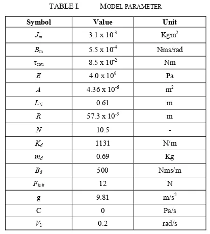
The model parameters are summarized in Table I. The values of the parameters were used in the simulation [7].
TABLE I. MODEL PARAMETER
Symbol Value Unit
Jm 3.1 x 10⁻³ Kgm2
Bm 5.5 x 10⁻⁴
Nms/rad
τcou 8.5 x 10⁻² Nm E 4.0 x 10⁹
Pa A 4.36 x 10⁻⁶
m2
LN 0.61 m
R 57.3 x 10⁻³
m
N 10.5 -
Kd 1131 N/m
md 0.69 Kg
Bd 500 Nms/m
Finit 12 N
g 9.81 m/s2
C 0 Pa/s
V1 0.2 rad/s
B. Influence of Radius
increase of radius of the winder. Thus, the change of radius influences the behavior of the system.
0 5 10 15 20 25 30 35 40
Fig. 9. Influence of radius on the system performance
Table III shows that the effect of changing the value of radius on damping ratio and natural frequency. The increase of radius will cause the increase of damping ratio and natural frequency.
TABLE II. INFLUENCE OF RADIUS ON PEAK OVERSHOOT, PEAK TIME AND SETTLING TIME
TABLE III. THE EFFECT OF CHANGING VALUE OF RADIUS ON DAMPING RATIO AND NATURAL FREQUENCY
Radius, R(m) Damping
Ratio Natural Frequency (rad/s)
0.02 0.28 0.77 different. It will cause the wire break or loosing.
C. Influence of Inertia of Motor
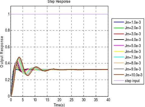
The system is tested with different values of inertia of motor, that is from 1.0 X 10⁻³kgm to 10.0 X 10⁻³ kgm. Fig. 10 shows that the influence of inertia of motor on the system performance. The peak overshoot, peak time and settling time is then recorded in Table IV. In Table IV, when the inertia of motor increases, the peak overshoot is increases rapidly. At the same time, the peak time and settling time are also increases. Thus, the change of motor inertia will affect the system performance.
Table V shows the effect of changing the value of inertia of motor on damping ratio and natural frequency. In Table IV, when motor inerta increased, the damping ratio and natural
Fig. 10. Influence of inertia of motor on the system performane
TABLE IV. INFLUENCE OF INERTIA OF MOTOR ON PEAK OVERSHOOT,
TABLE V. THE EFFECT OF CHANGING VALUE OF INERTIA OF MOTOR IN DAMPING RATIO AND NATURAL FREQUENCY
Inertia of Motor,
Jm (kg.m) Damping Ratio Natural Frequency (rad/s)
1.0e-3 0.732 5.21
The mathematical model is done before the simulations for the system is started. Since this project is mainly focused on the simulation, therefore the values of parameters are cited from a journal. The results obtained from the mathematical model is basically describe how the performance of the system.
For the parameter variation, different values of parameters are inserted into the system and the step response graph is
obtained to examine the effect of the increased parameters to the system. It can be concluded that the most influenced parameters is the changing of radius of winder. The changing of radius of winder will affect the velocity of the winder. When the velocity of take-up winder and velocity of pay-off winder are different, the winding tension problem occurs. It will cause the wire break or loosing. Therefore, it is needed to design a controller which robust to control the speed of the motor. In future the experimental setup should be build up in order to compare between simulation result and experimental result. A classical controller can be design in order to make the system has good performance.
ACKNOWLEDGMENT
Authors would like to thanks Universiti Teknikal Malaysia Melaka for providing all the facilities and grant (PJP/2014/FKE (13C)/S01352) on this research. Special thanks to Hitachi Computational Intelligence. Proceedings on the Third IEEE Conference, vol. 3, pp. 1654-1659, 1994.
[2] Ji Wengang, Luo Yu, Dai Fengyan, Cao Jianshu, “Research on Constant-Tension Control Based on Fuzzy Multiple Models”, Computational Intelligence and Design, 2008. ISCID ’08. International Symposium, vol. 1, pp. 112-115, 2008.
[3] H.K. Kang, C.W. Lee, K.H. Shin, S.C Kim, “Modeling and Matching Design of a Tension Controller Using Pendulum Dancer in Roll-to-Roll Systems”, IEEE Transactions on Industry Application, vol 47, pp. 1558-1566, 2011.
[4] John E.K, Raman U.:“Automatic Control of Unwind Tension in Film Finishing Applications” Industrial Electronics, Control and Instrumentation, Proceedings of the 1995 IEEE IECON 21st International Conference, Vol 2, pp. 774-779, 1995
[5] Norbert A.E., Ragnar A., Gerd M., Noel. D.S. “Tension Control: Dancer Rolls or Load Cells”, IEEE Transactions on Industry Application, vol 29, pp. 727-739, 1993
[6] Hakan K. Knittel D. Michel d.M, Gabriel Abba : “Modeling and Robust Control of Winding System for Elastic Webs”, IEEE Transactions on Control System Technology, Vol 10, pp. 197-208, 2002.
![Fig. 4 shows the sketch of wire winder system [7]. This](https://thumb-ap.123doks.com/thumbv2/123dok/484757.53195/3.595.270.538.99.513/fig-shows-sketch-wire-winder.webp)