VIBRATION-FREE POSITIONING OF GANTRY CRANE SYSTEM USING IMPULSE SHAPING METHOD
FAIZAL BIN AHMAD
This report is submitted in partial fulfillment of requirements for the Bachelor Degree of Mechanical Engineering (Design and Innovation) With Honours
Faculty of Mechanical Engineering Universiti Teknikal Malaysia Melaka
i
“I hereby declare that this report is the result of my own work except for quotes as cited
in the references.”
Signature : ……….
ii
“I hereby declare that I have read this report and in my opinion this report is sufficient in
terms of the scope and quality for award of Bachelor of Mechanical Engineering (Design and Innovation) With Honours.”
Signature : ..………
Supervisor’s Name: MR. ZAIRULAZHA BIN ZAINAL
iii
iv
ACKNOWLEDGEMENT
Bismillahhirrahmanirrahim.
First and foremost, I would like to thank Allah S.W.T for His blessing. He gave me all the strength needed to strive on my final year project up to the completion.
I take this opportunity to express my profoundest gratitude and deepest regards to all those who gave me the possibility to successfully complete this PSM. I am deeply indebted to my Project Supervisor, Mr. Zairulazha Bin Zainal. I wish to express a million thanks for his exemplary guidance, monitoring and constant encouragement throughout the development of the project. In those moments of uncertainty and doubts when things used to turn dark without a clear understanding of the knowledge that he tried to share, his kind and patient way of explaining had indeed a soothing effect. Your advise and support has really been a helping hands to keep me on the right track most of the times.
Not to mention for all any other colleagues and friends who have bothering themselves to aid me, be it from Universiti Teknikal Malaysia Melaka or from any other universities, thank you for your direct or indirect help, discussions and information
sharing. I am really in your great debt.
v
ABSTRACT
Impulse shaping reduces residual vibrations in computer controlled machines. Impulse shaping is implemented b y convolving a sequence of impulses, an input shaper with any desired command. The shaped command that results from the convolution are then is used to drive the system. If the impulses in the shaper are chosen correctly, then the system will respond without vibration to any unshaped command. In order to
vi
ABSTRAK
Teknik ‘Impulse shaping’ digunakan untuk mengurangkan gegaran pada mesin kawalan komputer. ‘ Impulse shaping’ dilaksanakan dengan menggabun gkan beberapa turutan denyutan yang dipanggil ‘input shaper’ dengan apa-apa arahan yang dikehendaki. Arahan yang dibentuk dari konvolusi tersebut akan digunakan untuk memandu sistem. Jika denyutan pada pembentuk dipilih dengan betul, maka sistem
vii
CONTENTS
CHAPTER TITLE PAGE
DECLARATION i
SUPERVISOR VERIFICATION ii
DEDICATION iii
ACKNOWLEDGEMENT iv
ABSTRACT v
ABSTRAK vi
CONTENTS vii
LIST OF FIGURES xi
LIST OF SYMBOLS xiv
I INTRODUCTION
1.1 Project Introduction 1
1.2 Objective 2
1.3 Problem Statement 3
1.4 Scopes 4
1.5 Work Methodology 5
viii
CHAPTER TITLE PAGE
II LITERATURE REVIEW
2.1 Input Shaping Techniques 7
2.1.1 Impulse Shaping 9
2.1.2 Command Shaping 13
2.1.3 Posicast Control 14
2.1.4 Inverse Dynamic Analysis 16
2.1.5 Zero Vibration 17
2.1.6 Zero Vibration and Derivative 19
2.1.7 Extra Insensitive 20
2.1.8 Input Shaping Residual Vibration Control 22
2.2 Background of a Gantry Crane 24
III RESEARCH METHODOLOGY
3.1 Introduction 31
3.1.1 Literature Review 32
3.1.2 Gantry Crane System 32
3.1.3 Design the Nonlinear Gantry Crane in Matlab Simulation Using the Impulse Shaping method 33 3.1.4 Test and Develop: Interface Between
Software and Hardware 33
3.1.5 Report Writing 34
ix
CHAPTER TITLE PAGE
IV MATHEMATICAL MODELING OF THE GANTRY CRANE
SYSTEM
4.1 Introduction 37
4.2 Model Description 39
4.3 Derivation of the Equations of Motion 40
V ANALYSIS AND RESULT
5.1 Simulation 44
5.2 Expected Results 48
5.3 Simulation Results 49
5.4 Result Analysis 54
5.4.1 Comparison between System With Controller
and Without Controller 54
5.4.2 Comparison with other input for the gantry
crane systems (Inverse dynamic Analysis) 57 5.4.3 Comparison with previous research of input
for the gantry crane systems
(Bang-Bang Input) 64
x
CHAPTER TITLE PAGE
VII CONCLUSION AND FUTURE WORK
6.1 Conclusion 70
6.2 Future Work 71
REFERENCES 72
xi
LIST OF FIGURES
NO TITLE PAGE
1.1 Methodology chart 5
2.1 Destructive interference time 8
2.2 Input shaping process 9
2.3 General system using impulse shaping 10
2.4 Impulse shaping process 10
2.5 Impulse shaper versus step shaper 12
2.6 Multi pulse shaped input 13
2.7 A lightly damped transient response 14
2.8 Posicast command 15
2.9 System output (dashed is uncompensated) 15
2.10 Input shaper 17
2.11 Use of two impulses to nullify payload vibration 17
2.12 ZV input shaping algorithm 18
2.13 ZVD input shaper response 19
2.14 Sensitivity curve 20
2.15 Fixed height steel gantry crane 25
2.16 Workstation gantry crane 26
2.17 EOT Gantry Crane 27
2.18 Pillar-mounted slewing jib crane 28
2.19 Wall-mounted slewing jib crane 28
2.20 Super-post panamax portainer crane 29
2.21 Double girder crane 30
xii
NO TITLE PAGE
4.1 Gantry crane model 39
5.1 Simulation model in Matlab 45
5.2 Pulse times for discrete impulse block 1 46 5.3 Pulse times for discrete impulse block 2 46
5.4 Expected result for trolley position 48
5.5 Expected result for swing angle 48
5.6 Functional block parameters for nonlinear model 50
5.7 Waveform for discrete impulse 1 51
5.8 Waveform for discrete impulse 2 51
5.9 Waveform for summing both discrete impulse 1 and 2 52
5.10 Waveform for Summing both discrete impulse 1 and 2
after gain of 2.6 52
5.11 Simulation result for position of the trolley usin g impulse
shaping 53
5.12 Simulation result for swing angle (radian) using impulse
shaping 53
5.13 Graph result for swing angle for system without controller and system with controller using impulse
shaping method 55
5.14 Graph result for positioning of gantry crane without
controller 55
5.15 Graph result for positioning of gantry crane using impulse
Shaping 55
5.16 Design Process for the inverse dynamic analysis 57 5.17 Parameters labeling at block mask editor 59
5.18 Block parameter for fcn 59
5.19 Block parameter for workspace 60
5.20 Open loop system for crane model with controller from
xiii
NO TITLE PAGE
5.21 Graph result of swing angle for system using impulse shaping technique versus system using inverse dynamic analysis 62 5.22 Graph Result for Positioning of Gantry Crane Using
Impulse Shaping 63
5.23 Graph Result for Positioning of Gantry Crane Using
Inverse Dynamic 63
5.24 Open loop system for crane model with controller from
bang-bang input 64
5.25 Comparisonof swing angle graph result for system using impulse shaping technique versus system using
bang-bang input 65
5.26 Comparisonof gantry crane’s positioning graph result for system using impulse shaping technique versus system
using bang-bang input 66
xiv
LIST OF SYMBOLS
M - Trolley mass m - Payload mass
l - Length of the hoisting rope F
x - Input force
G - Gravitational acceleration = 9.81ms-2
G - Centre point
S - Point of suspension x - Trolley position
x - Velocity x
- Acceleration
- Sway angle
- Angular velocity
1
CHAPTER I
INTRODUCTION
This chapter will discuss the overview of the project; mainly about how to reduce
the residual vibration in a gantry crane system using the impulse shaping closure. All the details regarding the project, such as introduction, objective, problem statement, scopes, work methodology and thesis outline will be revised thoroughly in this chapter.
1.1 Project Introduction
In our daily life, crane is generally used to lift, transfer and placed workloads that are too heavy or too large to be handled by human bare handedly. By hoisting or lowering desired loads vertically and then moving it horizontally, crane is one the most favor transportation system that is widely used in the industry to place massive loads. Some of the famous crane types are like the gantry crane, overhead crane, tower crane, jib crane and others. In this project, the research done is solely focused on the gantry crane system.
2
many studies have been conducted in order to solve this problem and one of it is the impulse shaping method.
Impulse shaping is a simple and effective method for reducing the residual vibration when positioning a lightly damped systems and it remains an active research area until now. In this proposed method the only parameter that needs to be defined is the output speed, which is limited only by the physical constraints of the drive system. The calculation of an optimum speed is demonstrated by simulation example.
In many machines, load positioning is achieved by simple open-loop control. In the case where structural flexibility is significant and the load is lightly damped, the vibration may be unacceptable and a number of papers from previous studies have
reported various approaches to use impulse shaping to control the vibration.
In order to increase the rise time when usin g impulse shaping, the impulse are allowed to take negative values, and multihump shaping of the impulses can be use to increase the system robustness. Of course the flex ible system that will be applied on this project is the gantry crane which has been mentioned earlier.
1.2 Objective
The main objective of this project is to design a gantry crane system and to apply the technique of the impulse shaping onto the gantry crane to control the
3
1.3 Problem statement
In man y machines, vibration is a serious problem e s p e c i al l y in t he mechanical systems that are required to perform precise motion in the presence of structural flexibility. Vibration control is an important consideration for rapid repositioning of flexible payloads. The large accelerations and speed needed to move a payload quickly can cause vibration, reducing the throughput of the overall process. Residual vibration is detrimental whenever the part must be quiescent before it can be accurately placed. Increasing the positioning speed will lead to residual vibration. If the time it takes to sufficiently damp the vibration for accurate placement is greater than the time gained through increasing the maneuver speed, then the overall effect is a reduction in throughput.
The use of the gantry crane systems for transporting payload is very common in industrial application. However, moving the payload using the crane is not an easy task especially when strict specifications on the swing angle and on the transfer time need to be satisfied. The fundamental motions of a gantry crane consist of travelling, load hoisting and load lowering. When the gantry crane start or finished the operation, it will give the undesirable result where it is swinging and vibration to the suspended load.
Gantry cranes are highly flexible, responding in an oscillatory manner to external disturbances and motion of the bridge and trolley. Payload oscillation has adverse consequences. Swinging of the hook makes positioning difficult and inefficient. When the payload or the surrounding obstacles are of a hazardous or fragile nature, the
4
Moreover, the gantry crane needs a skillful operator to control manually to stop the swing immediately at the right position. It is also makes crane work ver y dangerous when workers or other obstacle exist in the crane workspace. The failure of controlling crane might cause accident and may harm people and the surrounding.
Furthermore, to unload, the operator has to wait the load stop from swinging. The residual vibration at the end of a move is the most determination and extent of the residual vibration limits the performance of the system.
The impulse shaping method will applied to this gantr y crane to reduce the vibration of positioning of the crane and also reduces the swing angle of the payload.
1.4 Scopes
The scope of this project includes:
I. To study the dynamic behavior of gantry crane. II. To study the impulse shaping method.
III. To design an appropriate way based on impulse shaping method to reduce the residual vibration of the system.
5
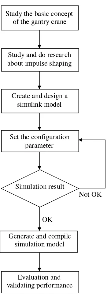
1.5 Work Methodology
Study the basic concept of the gantry crane
Study and do research about impulse shaping
Create and design a simulink model
Set the configuration parameter
Simulation result
Not OK
OK
Generate and compile simulation model
[image:20.595.262.437.157.648.2]Evaluation and validating performance
6
1.6 Thesis Outline
This section will illustrate the rough outlines of the structure of the thesis. Below is the general idea of what each and every chapter in this thesis will convey.
Chapter 1 will discuss the introductory phase of this thesis. The background, objective, scopes and work methodology of this project can be come across here.
Chapter 2 is most likely deal with the literature review of the project. A review of recent work on impulse shaping theor y and its application is presented in this chapter. In addition of that, review of the gantry crane also stated here.
Chapter 3 will cover up the methodology of this project. A detail flow chart regarding the course of the project is also presented here.
Chapter 4 gives a detailed description of the derivative of the equations of motion used for the time – domain simulation.
Chapter 5 will discuss the analytical impulse shaping approach for nonlinear excitation terms. Simulated verification of the method is also described in this chapter.
7
CHAPTER II
LITERATURE REVIEW
Precise position control and rapid rest-to-rest motion is the desired objective in a
variety of applications. The requirement of precise position control implies that the residual vibration of the structure should be zero or near zero. Literature review is done in this chapter to make a review of the several techniques of input shaping that will reduce the vibration and part of it is discussed below.
2.1 Input Shaping Techniques
Input shaping is a simple and effective method for reducing the residual vibration when positioning a lightly damped system. A lightly damped system is a system which oscillates with a damped frequency until it stops and in this project, the gantry crane system is what it refers to as a lightly damped system. In real-world systems, the second
8
relative to the crane movement but will eventually damping upon stationary motion as the crane stop moving.
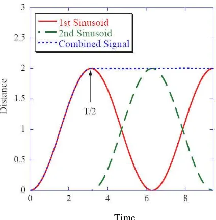
Input shaping is applicable in real time, and input shapers can be designed to have any desirable robustness level. Input shaping is designed to reduce, or eliminate, command-induced system vibration [1]. A desired reference command given to a flexible system will, in general, result in residual vibration. Input shaping is ability to cancel vibration can be viewed as destructive interference of sinusoidal waves [2]. If two sinusoids of the same magnitude, same frequency and correct phase shift between them are added together, the resulting combination will have no oscillations. This effect can be seen in Figure 2.1.
[image:23.595.213.425.343.559.2]Time
Figure 2.1: Destructive Interference Time
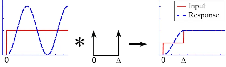
9
Figure 2.2: Input shaping process.
As shown in Figure 2.2, this modified command will cause the system to move with no residual vibration. The sequence of impulses is chosen such that, when the modified command is applied to the system, certain performance constraints are met. These performance constraints can include the system’s desired residual vibration amplitude, robustness to modeling errors, and command rise time, among others.
Some of the well-heard input shaping techniques is such as impulse shaping, posicast control, inverse dynamic and others.