Study on Analog Front End of Passive UHF RFID
Transponder
Dayanasari Abdul Hadi, Norhayati Soin
Dept. of Electrical EngineeringUniversity of Malaya
Lembah Pantai, 50603 Kuala Lumpur. [email protected]
Abstract-In this paper, an overview of passive Ultra High Frequency (UHF) Radio Frequency Identification (RFID) is presented. This literature review emphasis on the analog front end part of the RFID transponder based on several published papers conducted by previous researchers. A passive UHF RFID transponder chip design was proposed using 0.18 µm standard CMOS process. It is estimated to have power of 1µW and high efficiency that greater than 32%. This design will work in the range of frequency between 900MHz to 960MHz.
I. INTRODUCTION
Radio Frequency Identification (RFID) has existed for more than 20 years, but it is only in recent years that it has gained significant popularity for personal identification used in our ID card, smart tag application, livestock identifications, tracking goods in supply chains [1] and also biomedical applications [2]. This technology has replaced the conventional way of in barcode usage in our department store these days. Figure 1 shows the evolution of cost effective of RFID based on its applications [3].
Figure 1. Evolution of cost effective of RFID applications [3]. Communication takes in place between a reader (interrogator) and a transponder (tag) and they operate in a wide range of frequencies from 125 kHz to 2.45GHz depends on the application. They are categorized by:
•Low Frequency (LF) operates at < 135 kHz •High Frequency (HF) operate at 13.56 MHz
•Ultra High Frequency (UHF) operate at 850 – 960 MHz •Microwave operates at 2.45 GHz
All these operation modes are depending on the purpose of their usage. For instance, the Low Frequency (LF) is use for animal tracking while Ultra High Frequency (UHF) mostly used in product tracking, inventory system and payment system.
The objective of this paper is to understand key concept behind the RFID technology research especially the passive UHF RFID tag itself. Its give an overview of it historical trends, basic principle operation which characterize the function of its system, applications and design requirement. This work had been done by examined various papers, publications and journals that related to the RFID technology, its application and design requirement.
This paper had been organized as follow: history of the RFID, basic principle of RFID, RF-analog front end blocks architecture, discussion and conclusion. It is hoped that this review paper will provide an insights into the technology and becomes a useful resource to others.
II. HISTORY OF RFID
It is says that the radio frequency (RF) communication development started in 1906 by Ernst F. W. Alexanderson whom demonstrated the first the continuous wave radio generation and its transmission signal [4-6]. Around 1922-1935, RF technology has undergone significant development in the military field to track military equipment
and personnel. Then, with combination of radar technology,
it had been used in the Identity Friend and Foe (IFF) system that can detect their own returning or enemy aircrafts.
In 1960s, the electronic article surveillance (EAC) system had been introduced using the RF technology for the anti-theft purposes. Since then the radio frequency identification (RFID) become popular and demanding. Thus, it had been used by many companies during that time until today. The EAC tag is a 1 bit tag where it can be either in the ‘on’ or ‘off’ state. The operation is simply where it is attached to a product and when the product is paid, the tag is ‘off’ and when the product leaves the store without paying, it will be in the ‘on’ state and thus an alarm will be triggered.
In the late 1970, the RFID advance development had shifted this technology to a new era of the tracking system especially for animal and vehicle tracking. For example, the Los Alamos Scientific Laboratory scientists released their research work on the animal tagging system [4-6].
The RFID technology development does not stop there; it has been continued work by researchers, developers and academicians in order to enhance and develop the RFID with high performance and low cost requirement that suit the recent costumer demands. The development must be able to operate under regulations from various countries and compatible among different vendors. Therefore standard specification is important to control the usage of RFID technology.
So, this project also a continuation works from previous researchers and developers. In this project, a passive UHF RFID transponder will be designed based on 0.18µm CMOS process technology provided by SILTERRA. This design will have a low power consumption estimated 1µW. Apart from that, the design will have a high efficiency and thus it will maximized the communication distance between the reader and the transponder.
III.BASIC PRINCIPLE OF RFID
A. Overall RFID System Operation
Basically, there are three important elements in the RFID system, namely transponder or tag, reader and computer also known as host as shown in Figure 2. A typical transponder attached to an object and has internal memory that store required information of the object including its serial number, manufacture date and other important data. Meanwhile the reader transmits RF energy and when the transponder passes through this energy field, they (transponder) transmit it information back to the reader thereby identifying the objects. Lastly, the computer acts as a data processing equipment that monitor and store the object’s information in a system for user usage.
The communication between the transponder and reader is managed and controlled by one of several protocols like the ISO 15693 and ISO 18000-3 for HF or the ISO 18000-6, and EPC for UHF. The number of tags that can be identified depends on the frequency and protocol used, and can typically range from 50tags/s for HF and up to 200tags/s for UHF. Anti-collision algorithm is introduced in order to allow transponders to be sorted and individually selected so that reader manages to read them at one time.
Figure 2. RFID system components [16].
B. Passive RFID Transponder Architecture
There are two types of RFID transponder namely passive transponder and active transponder. The active transponder has internal battery in its chip which is used to power any ICs that generate the outgoing signal meanwhile the passive one depend on the electromagnetic generated by the RFID reader in order to get activated. Table 1 shows the differences between active and passive transponder [5]:
TABLE I
COMPARISON BETWEEN ACTIVE AND PASSIVE TRANSPODER [5]
Active RFID tag Passive RFID tag
Tag power source Internal to tag Energy transferred
from the reader Availability of tag
power
Continuous Only when found in
the field of the reader Required signal
strength from reader to tag
Low High
Available signal strength from tag to reader
High Low
Communication range Long range Short range
Multi-tag collection Scanning of thousand
of tags from a single reader. Scanning up to 20 tags moving at more than 100 miles/hour.
Scanning hundred of tags within 3 meters from a single reader. Scanning 20 tags moving at 3 miles/hour or slower.
Sensor capability Ability to monitor
continuously monitor sensor input.
Monitor sensor input when tags is powered from the reader.
Data storage Large Small
From the table above, it shows that the active transponder has more capability compared to the passive one. However in the product identification or biomedical applications, it’s required to have as small transponder as possible. Thus, the passive transponder is more popular used such applications nowadays since there is no additional built-in battery require in the circuit itself. The passive transponder is designed in such way in order to have the capability to generated power supply internally. Many researches had been conducted in order to have a small transponder with high performance possible [7, 8].
Figure 3 shows the proposed block diagram of passive RFID transponder used in this work. The transponder consists of antenna transponder and transponder chip. The transponder chip itself contains 3 major parts which are RF-analog front end, a digital clock control and a non-volatile memory as shown in Figure 3. Then the RF-analog front end the passive RFID transponder consists of voltage rectifier, demodulator, clock generator and modulator. All blocks in the RF-analog will be discussed in detail in the next section since this work will focus in the RF-analog section only.
IV.RF-ANALOG FRONT END BLOCKS ARCHITECTURE
The RF-analog front end block of the transponder is a large current consumer. We know that, the radiated RF signal travel from a reader to a transponder in a distance, it will losses energy and hence the transponder antenna receive a small amount of the energy that need to be used by other circuitry in it system. So, it is important to design the RF-analog front block in such way so that its have sufficient power to supply to the entire chip without compromising the performance of the circuit. Many researches had been conducted due to overcome this issue [1, 8].
A. Voltage Rectifier
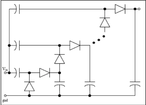
The voltage rectifier is the main block in the passive RFID transponder chip since it provides the needed DC power to the other blocks in the transponder system. It converts the AC signal receive by the antenna into DC voltage. The most technique use in designing rectifier is the multi stage rectifier as shown in Figure 4.
Figure 4. N-stage rectifier circuit [9].
In paper [9, 10], diode connect NMOSFET that has low threshold voltage is used in the multistage rectifier design instead of Schottky diode used by paper reference [11]. Compared with the case using Schottky diodes, the utilized approach saves the fabrication cost for extra masks the Schottky diode needs.
B. Demodulator
The function of the demodulator is to convert the pulse-width modulated input signal to digital data and generates a
synchronous system clock. The demodulator block consists of envelope detector, a low pass filter and a comparator as shown in Figure 5. The envelope detector is use to detect the envelope in the RF signal and transferred through a low pass filter to get its average value, and two values are then compared using a comparator. The comparator act as a decision device based on the low power OTA. In one paper [12], it uses the Schottky diode in ASK demodulator circuit that used to demodulate the ASK signal by envelope detection mechanism.
Author of reference [13] use PWM demodulator implemented in their design. The basic PWM demodulator circuit is based on the integrator and followed by comparator shown in Figure 6.
Figure 5. ASK demodulator circuit schematic [15].
Figure 6. PWM demodulator circuit [13].
C. Modulator
The PSK backscatter modulation is for reverse link modulation. When the base station transmits a continuous- wave (CW) carrier, by changing the transponder’s impedance, the electromagnetic wave scattered back by the antenna is modulated. Figure 7 shows the schematic of the modulation circuit.
Vin
Figure 7. PSK modulator circuit [10].
D. Clock Generator
The clock generator circuit is based on RC relaxation oscillator [13]. The principle of operation of the circuit is shown in Figure 8. The capacitor Cosc charges when the output is low and discharges when the output is high.
Figure 8. Clock generation circuit [13].
V. DISCUSSION
In this paper, a literature review of the RFID technology had been conducted. It shows that the technology itself growth rapidly especially in 20s century until today and it shows no stopping sign to it. This paper had presented the important art of starting a project which is literature review.
In this project itself, a passive UHF RFID transponder will be developed and designed based on 0.18µm CMOS process technology provided by SILTERRA. Through this literature review, it seems that low power consumption is one of the important key in design a transponder especially in UHF range. So, our design will estimate the power consumption of 1µW and the optimizations factor will be considered in the design. Beside that, this design also will have a high efficiency so that it will maximize the
communication distance between the reader and the transponder.
Table 2 shows proposed design metric of this project and comparison to other previous works. This table shows that both works in [10] and [14] used the same standard 0.18µm CMOS process and they have almost the same efficiency value compared to work done by [13] that shows it has better efficiency by using smaller CMOS technology. Since SILTERRA provided us with 0.18 µm CMOS technology, we estimated our design to have the performance same as work done by [13] due to its low power 1µW and high efficiency 32% compared to other 2 works based on Table 2.
TABLE 2
PROPOSED DESIGN METRICS IN COMPARISON WITH OTHER WORKS
PR
A passive UHF RFID transponder chip design was proposed using 0.18 µm standard CMOS process. It is estimated to have power of 1µW and high efficiency that greater than 32%. This design will work in the range of frequency between 900MHz to 960MHz.
REFERENCES
[1] N.C. Wu, M.A. Nystrom, T.R. Lin, H.C. Yu, “Challenges to global
RFID adoption,” Technovation, Volume 26, Issue 12, pp. 1317-1323, December 2006.
[2] Inke Jones, Lucas Ricciardi, Loenard Hall, Hedley Hansen, Vijay
Varadan, Chris Bertram, Simon Maddocks, Stefan Enderling, David Saint, Said Al-Sawari, Derek Abbott, “Wireless RF communication in biomedical applications,” Smart Materials and Structures, Volume 17, 2008, 10.1088/0964-1726/17/1/015050.
[3] ZHANG Xiao-dan, YUE Shu-jie, WANG Wei-min, “The review of
RFlD applications in global postal and courier services,” The Journal of China Universities of Posts and Telecommunications, Volume 13,
Issue 4, p. 106-110, December 2006.
[4] Jeremy Landt, “Shrouds of time the history of RFID” The Association
for Automatic Identification and Data Capture Technologies, ver. 1.0, October 2001.
[5] Kanstantinos Domdouzis, Bimal Kumar, Chimay Anumba,
[6] C.M. Roberts, “Radio Frequency Identification (RFID),” Computers and Security, Volume 25, pp. 18-26, 2006.
[7] Tao Yuan, Chengwei Qiu, Le-Wei Li, Qun Zhang, Mook-Seng Leong,
“Passive RFID-Tag design using discrete components,” Proceeding of
ISA, 2007
.
[8] Zhihua Wang, Xuguang Sun, Chun Zhang, Yondming Li, “Issues in
integrated Circuit design for UHF RFID,” IEEE International Workshop on Radio-Frequency Integration Technology, p.p. 9-11, 2007.
[9] Yang Hong, Chi Fat Chan, Jianping Guo, Yuen Sum Ng, Weiwei Shi,
Lai Kan Leung, Ka Nang Leung, Chiu Cing Choy, Kong Pang Pun, “Design of passive UHF RFID Tag in 130nm CMOS technology,” IEEE Asia Pacific Conference on Circuits and Systems, p.p. 1371-1734, 2008.
[10] Alessio Facen, Andrea Boni, “A CMOS analog frontend for a passive
UHF RFID tag,” International Symposium on Low Power Electronic and Design (ISLPED) 2006, p.p. 280-285, 2006.
[11] Ray Barnett, Steve Lazar, Jin Liu, “Design of multistage rectifiers
with low-cost impedance matching for passive RFID tags,” Radio Frequency Integrated Circuits (RFIC) Symposium, 2006.
[12] Ching-Cheng Tien, Chih-Hu Wang, Yi-Cheng Hong, Chih-Hao Chen,
Hsuan-Chih Lu, “Implementation of Novel EPC UHF RFID Tag with Sensor Data Transmission Capability,” Chung Hwa Journal of Science and Engineering, Volume. 6, No. 4, pp. 37-42, 2008.
[13] Ahmed Ashry. Khaled Sharaf, magdi Ibrahim, “A compact low power
UHF RFID tag,” Microelectronics Journal, 2009.
[14] Soumyajit Mandal, Rahul Sarpeshkar, “Low power CMOS rectifier
design for RFID applications”, IEEE Transactions on Circuits and Systems, Volume 54, No. 6, p.p. 1177-1188, June 2007.
[15] Nhan Tran, Bomson Lee, Jong-Wook Lee, “Development of
Long-Range UHF-band Tag chip using Schottky Diodes in Standard CMOS Technology”, IEEE Radio Frequency Integrated Circuit Symposium 2007, pg. 281-284, 2007.
[16] http://www.hightechaid.com/Images/Page/rfidsystem.gif, 20/08/2009,
![Figure 1. Evolution of cost effective of RFID applications [3].](https://thumb-ap.123doks.com/thumbv2/123dok/627402.75858/1.595.46.289.423.567/figure-evolution-cost-effective-rfid-applications.webp)
![Figure 3. A passive RFID transponder diagram [13].](https://thumb-ap.123doks.com/thumbv2/123dok/627402.75858/2.595.303.557.186.460/figure-a-passive-rfid-transponder-diagram.webp)
![Figure 8. Clock generation circuit [13].](https://thumb-ap.123doks.com/thumbv2/123dok/627402.75858/4.595.38.284.310.521/figure-clock-generation-circuit.webp)
