Single-band and Dual-band Artificial Magnetic Conductor
Ground Planes for Multi-band Dipole Antenna
Maisarah ABU
1, Mohamad Kamal A. RAHIM
21
Dept. of Telecommunication Eng., Universiti Teknikal Malaysia Melaka, Hang Tuah Jaya, 76100 Durian Tunggal, Melaka Malaysia
2
Dept. of Radio Communication Engineering, Universiti Teknologi Malaysia 81310 UTM JB, Johor Bahru, Malaysia
[email protected], [email protected]
Abstract. Two new designs of high impedance surface
(HIS) structure are presented, namely zigzag and slotted rectangular with I-shaped slot Artificial Magnetic Con-ductor (AMC). The zigzag AMC is designed based on the straight dipole AMC. The zigzag AMC is introduced to minimize the AMC size and to be suitable for UHF RFID applications. On the other hand, the slotted rectangular with I-shaped slot AMC is designed to operate at 0.92 GHz and 2.45 GHz. The slot is loaded in the main patch of the AMC to create the other resonant frequency. By using this technique the resonant frequency can be lowered, and hence reduce the size of the AMC. Both structures are designed using the same dielectric substrate that is Ta-conic TLC-32. The properties of the AMC are investigated such as the reflection phase, reflection magnitude and surface impedance. The designed AMCs then are used as a back plane for the printed multi-band dipole antenna. By introducing the AMC as a ground plane (GP) for the printed dipole antenna, the gain of the dipole antenna is increased.
Keywords
Artificial Magnetic Conductor (AMC), high impedance surface, printed dipole antenna, RFID and zigzag AMC.
1.
Introduction
The radiation characteristics and input impedance of the dipole antenna will be distorted when the antenna is placed on a metal object [1-3]. This is because, the elec-tromagnetic wave is reflected almost entirely by the metal-lic surface and a 180 phase shift is occurred. By nature, the conventional ground planes exhibit the property of phase reversal of the incident currents resulting destructive interference of both dipole antenna and image currents. The same scenario happens when the dipole tag antenna is attached to a metallic object, the tag cannot be powered up by the field strength emitted by the Radio Frequency Iden
tification (RFID) reader since the metallic object reflects Radio Frequency (RF) wave. The impedance of the tag antenna, resonant frequency of the antenna and radiation efficiency will be changed due to the parasitic capacitance between the tag antenna and the metallic object. To over-come this problem, the antenna is placed at a quarter-wavelength above the metallic ground plane, making the antenna bulky at low frequencies [4]. Another way to minimize the effects of the parasitic capacitor between the dipole antenna and metallic object and the effect of the reflection of the RF wave by metallic object, a gap between tag antenna and the metallic object is placed and dielectric material between them is added [5].
Thus one way to reduce the size of the antenna, the high impedance surface structure is introduced to act as Perfect Magnetic Conductor (PMC) which does not exist in nature [6 - 12]. Its structure can be realized by artificially engineered, thus it is called as Artificially Magnetic Con-ductor. The AMC or PMC condition is characterized by the frequency or frequencies where the magnitude of the re-flection coefficient is +1 and its phase is 0. It has high surface impedance (Zs) and it reflects the external
electro-magnetic waves without the phase reversal. In contrast, the Perfect Electric Conductor (PEC) has a reflectivity of -1 and has electromagnetic waves out of phase with the inci-dent waves. As the metallic plate, the AMC also can be used as a ground plane to redirect the back radiation and provide shielding to the antennas.
2.
Artificial Magnetic Conductor
Design
Two different types of single-band 0.92 GHz AMC have been proposed in this work which is square patch and zigzag types of AMC. This paper also presents dual-band AMC called slotted rectangular with I-shaped slot AMC. The performance of the AMC with the dipole antenna has been investigated and analyzed at 920 MHz and 2.45 GHz RFID systems.
2.1
Single-band AMC Design
This section describes the designs of single-band AMC that are to be incorporated with the printed dipole antenna. As initial design, the properties of the square-patch AMC are investigated followed by the straight dipole AMC operating at 920 MHz.
2.1.1 Square Patch AMC - HIS Design at 0.92 GHz
This section describes the design of 0.92 GHz square-patch AMC-HIS that is capacitive square-square-patch frequency selective surface (FSS) backed by a ground plane with 0.035 mm thickness. This AMC is designed using the sub-strate parameters; permittivity r = 3.2, thickness h =
6.35 mm and tangent loss = 0.003. The characteristics of the AMC such as the reflection phase, reflection magnitude and surface impedance of the AMC are simulated using the transient solver in CST Microwave Studio.
The inductance (L), capacitance (C), resonant fre-quency (fr) and bandwidth (BW) are given by [7], [13]: between adjacent patches.
At resonance the surface impedance Zs is determined
by:
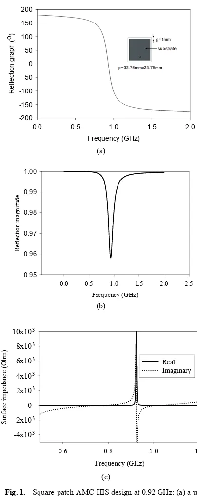
The unit cell and the reflection phase of 0.92 GHz square-patch AMC are shown in Fig. 1(a). The designed AMC has a patch width of 67.5 mm and the gap between the elements is 2.5 mm. Based on the equations (1) to (3), the calculated AMC resonant frequency is 918.83 MHz where C is 3.76 pF and L is 7.98 nH. cell and reflection phase, (b) reflection magnitude, and (c) surface impedance.
As shown in Fig. 1(a), the reflection phase varies from 180 to -180. At 0.92 GHz, the reflection phase is 0 and at 90 reflection phase, the frequency is laid between 0.88 GHz to 0.98 GHz. Fig. 1(b) and (c) show that the capacitive FSS backed by a ground plane has a reflection magnitude of 0.96 corresponding to –0.35 dB and has a very high impedance at the resonant frequency.
2.1.2 Zigzag Patch AMC - HIS Design at 0.92 GHz
r
0.92 GHz. Fig. 2 shows the straight dipole AMC at 920 MHz.
Fig. 2. A straight dipole AMC-HIS design at 0.92 GHz.
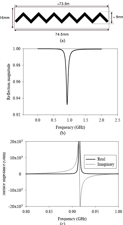
A unit cell size reduction of the straight dipole AMC is then realized by the configuration proposed in Fig. 3(a) namely the zigzag dipole AMC (74.5 mm x 16 mm). When the straight dipole is compared to the zigzag dipole AMC, there is an 18% size reduction of the unit cell with the zigzag dipole configuration. The simulated reflection mag-nitude and surface impedance of the zigzag dipole AMC are plotted in Fig. 3(b) and (c), respectively. The AMC structure has a reflection coefficient of 0.93 or -0.61 dB with very high impedance around the operating frequency.
(a)
0.80 0.85 0.90 0.95 1.00
S cell, (b) reflection magnitude, and (c) surface impedance.
Fig. 4 shows the reflection phase diagram of the zig-zag dipole and square-patch 0.92 GHz AMC-HIS. From the plotted diagram, the computed AMC bandwidth of the zigzag dipole is 6.94% while the AMC bandwidth of the square-patch AMC is almost double. However, the zigzag dipole configuration produces an AMC size reduction four times smaller than the square-patch AMC.
Frequency (GHz)
Fig. 4. The reflection phase of the zigzag dipole and square-patch AMC-HIS design at 0.92 GHz.
2.2
Dual-band AMC Design - Slotted
Rectan-gular with I shape Slot AMC - HIS
A new structure of the dual-band AMC is designed using rectangular patch with the slotted rectangular and I-shaped slot as shown in Fig. 5(a). The slot is loaded in the rectangular patch to achieve multi-band AMC as in [14]. This textured structure is printed on TLC-32 substrate too to resonate at 0.92 GHz and 2.45 GHz. To achieve the desired operating frequencies, this structure is designed with a rectangular slot width (ws) of 1 mm at the centre of
(c)
Frequency (GHz)
0.80 0.85 0.90 0.95 1.00
S
Fig. 5. Slotted rectangular with I-shaped slot AMC-HIS de-sign at 0.92 GHz and 2.45 GHz: (a) a unit cell, (b) re-flection phase, (c) rere-flection magnitude, and (d) sur-face impedance.
the rectangular patch, Ix of 7 mm and Iy of 4.5 mm. The simulated reflection phase and the reflection magnitude of the rectangular patch with slotted rectangular and I-shaped slot are plotted in Fig. 5(b) and (c), respectively. The re-flection magnitude of 0.95 and 0.90 is obtained at low and upper frequency. As can be seen in Fig. 5(d), high surface impedance is plotted at the resonant frequencies.
3.
Multiband Printed Dipole Antenna
Design
To cover three RFID frequencies, the dipole antenna is designed at three different frequencies, with centre fre-quency of 0.92 GHz, 2.45 GHz and 5.8 GHz. The antenna
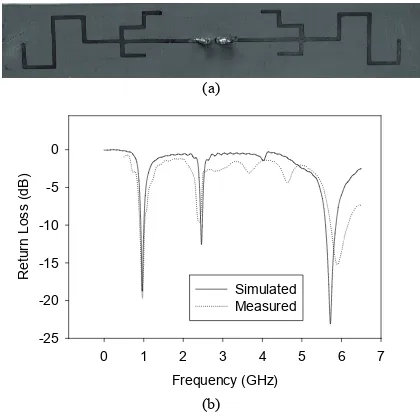
is designed based on monopole antenna proposed in [15], then is modified to become a straight dipole antenna pre-sented in [16]. In order to reduce the size of the straight dipole antenna, the main and second resonator dipole ele-ment is meandered as shown in Fig. 6(a). This multi-band meandered dipole antenna is printed on one side of the Taconic RF-35 substrate (permittivity = 3.54, thickness = 0.508 mm and tangent loss = 0.0019) with a substrate size of 145 mm x 20 mm. To become a UHF or MWF tag, the microchip operating at UHF or MWF frequency then is placed at the centre of the printed dipole antenna with an input impedance of 50 .
(a)
(b)
Fig. 6. Multi-band meandered dipole antenna: (a) The fabri-cated dipole antenna, (b) the simulated and measured return loss of the dipole antenna.
4.
Multiband Dipole Antenna with
AMC - HIS
4.1
Multiband Dipole Antenna Attach with
0.92 GHz Zigzag Patch AMC-HIS Ground
Plane
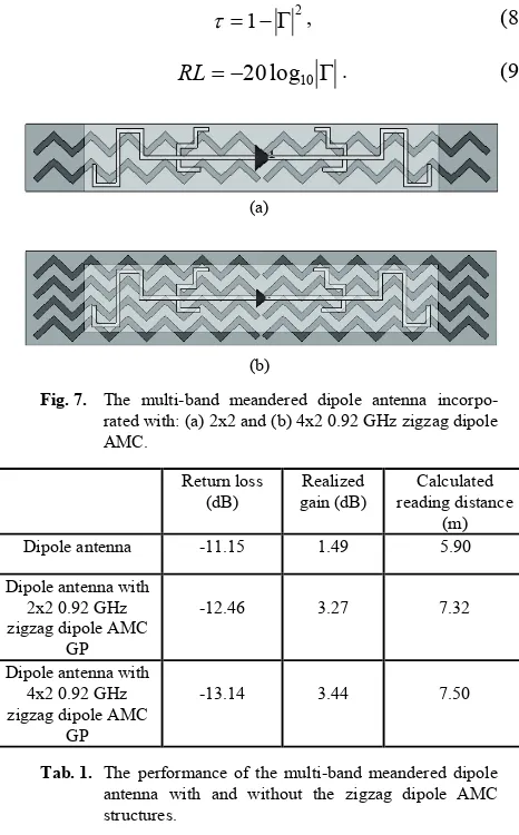
The performances of the meandered dipole antenna with the zigzag dipole AMC-HIS GP are investigated in this section. The configurations of the multi-band mean-dered dipole antenna with the AMC structures are given in Fig. 7.
From the simulation results, there is only a slight in-crease in directivity when the unit cell of the zigzag dipole is increased from two to four unit cells. Thus this corre-sponding value only gives the calculated reading distance difference of 0.18 m. Equation (7) is a formula to calculate the reading distance for a radio power link [17]:
where Preader-tx is the output power of the reader, Greader-ant
is the gain of the reader antenna, R is the distance between the reader antenna and the tag, Gtag-ant is the gain of the tag
antenna, λ is the wavelength in free space at the operating frequency, Ptag-threshold is the minimum threshold power to
power up the microchip and χ is the polarization matching coefficient between the reader antenna and tag antenna. If the two antennas are perfectly matched in polarization, χ will be 1. For most far-filed RFID system, the reader an-tenna is circularly polarized while the tag anan-tenna is line-arly polarized, thus χ will be 0.5 and τ is the power trans-mission coefficient determined by the impedance matching between the tag antenna and the microchip. The relation between the power transmission coefficient and reflection coefficient Γis given in equation (9).
Fig. 7. The multi-band meandered dipole antenna incorpo-rated with: (a) 2x2 and (b) 4x2 0.92 GHz zigzag dipole AMC.
Dipole antenna with 2x2 0.92 GHz zigzag dipole AMC
GP
-12.46 3.27 7.32
Dipole antenna with 4x2 0.92 GHz zigzag dipole AMC
GP
-13.14 3.44 7.50
Tab. 1. The performance of the multi-band meandered dipole antenna with and without the zigzag dipole AMC structures.
In the experimental work, the measured return loss of the dipole antenna with zigzag dipole AMC GPs generally degrades due to the fabrication and measurement error. For instance, the dipole antenna with the 4 x 2 0.92 GHz zigzag dipole AMC only works at 75% transmission power com-pared to the 95% transmission power in simulation. Be-sides that, the difference between the measured and calcu-lated reading distance of 0.5 m in free space is recorded for the dipole antenna with the bigger zigzag dipole AMC GP. As expected, the measured received power of the dipole antenna backed by 4 unit cells of the zigzag dipole AMC is
slightly higher than the received power of dipole antenna with 2 unit cells of zigzag dipole AMC.
The measurement of the reading distance of the tag with and without AMC GP is performed in free space us-ing UHF Gen 2 Reader Module and 2.45 GHz RFID reader with reader antenna gain of 9 dBi and 7.5 dBi respectively. The layout of the RFID tag range measurement is illus-trated in Fig. 8. Tab. 2 shows the return loss simulated and measured result of multi-band dipole antenna attached with 2x 2 and 4 x 2 zigzag dipole AMC-GP. Tab. 3 shows the measured reading distance of the triple band dipole antenna attach with AMC GP.
Fig. 8. The layout of the RFID tag range measurement in free space.
Return Loss (dB)
Simulated Measured
Dipole antenna with 2x2 0.92 GHz zigzag
dipole AMC GP
-12.46 -7.56
Dipole antenna with 4x2 0.92 GHz zigzag
dipole AMC GP
-13.14 -6.15
Tab. 2. The simulated and measured results of the multi-band meandered dipole antenna with the 2x2 and 4x2 0.92 GHz zigzag dipole AMC-HIS GP.
Measured reading
distance (m)
Dipole antenna 4.00
Dipole antenna with 2x2 0.92 GHz
zigzag dipole AMC GP 6.50 Dipole antenna with 4x2 0.92 GHz
zigzag dipole AMC GP 7.00
Tab. 3. The measured reading distance of the multi-band meandered dipole tag antenna with and without the 2x2 and 4x2 0.92 GHz zigzag dipole AMC-HIS GP.
Frequency, MHz
914 916 918 920 922 924 926
P
dipole without AMC GP
dipole with 2x2 zigzag dipole AMC GP dipole with 4x2 zigzag dipole AMC GP
Fig. 9. The measured power received by the triple-band mean-dered dipole antenna with and without the 0.92GHz AMC ground planes.
Fig. 9 shows the power received for the dipole an-tenna attach with zigzag dipole AMC-GP. The measure-ment is performed in anechoic chamber with transmitted power of 30 dBm. The measured reading distance had been increased from 4 m to 7 m using 4x2 zigzag dipole AMC-GP. It shows that increasing the number of unit cell of the AMC will increase the reading distance for the RFID sys-tem.
4.2
Multi-Band Dipole Antenna and Slotted
Rectangular with I-Shaped Slot AMC-HIS
GP
Tables 4 and 5 summarize the simulated data obtained for the triple-band meandered dipole antenna with and without the slotted rectangular with I-shaped slot AMC structures at 0.92 GHz and 2.45 GHz. At 0.92 GHz, the dipole antenna with the 2 x 2 slotted rectangular with I-shaped slot AMC-HIS GP has a better input match and higher gain compared to the dipole antenna with the 2 x 1 slotted rectangular with I-shaped slot AMC-HIS GP. But at 2.45 GHz, its return loss declines slightly to 8.56 dB, pro-ducing a decrease in total efficiency as well. By comparing the dipole antenna with the designed dual-band rectangu-lar-patch with rectangular slot AMC, a higher realized gain of the dipole antenna with this new design AMC GP is obtained. Dipole antenna with
2x1 dual-band AMC GP
-15.71 4.40 8.46
Dipole antenna with 2x2 dual-band AMC
GP
-26.98 5.46 9.68
Tab. 4. The performance of the multi-band meandered dipole antenna with and without the rectangular-patch with slotted rectangular and I-shaped slot AMC structures at 0.92 GHz.
Dipole antenna with 2x1 dual-band
AMC-HIS GP
-13.42 4.43 1.88
Dipole antenna with 2x2 dual-band
AMC-HIS GP
-8.56 6.43 2.25
Tab. 5. The performance of the multi-band meandered dipole antenna with and without the slotted rectangular with I-shaped slot AMC structures at 2.45 GHz.
The Cartesian plot of the meandered dipole antenna at 0.92 GHz and 2.45 GHz is plotted in Fig. 10. What is in-teresting in this finding is the significant increase of
direc-tivity. The back radiation of the antenna is redirected be-cause the AMC acts as a reflector like the PEC or metallic plate. Unlike the PEC, the dipole antenna can be mounted directly onto the metallic plate by introducing the high impedance surface in between them without performance degradation.
Triple-band meandered dipole antenna dipole antenna w 2x1 rec patch w slotted rec & I-shaped slot AMC
dipole antenna w 2x2 rec patch w slotted rec & I-shaped slot AMC
triple-band meandered dipole antenna dipole antenna w 2x1 rec patch w slotted rec & I-shaped slot AMC
dipole antenna w 2x2 rec patch w slotted rec & I-shaped slot AMC
(b)
Fig. 10. The Cartesian plot of the meandered dipole antenna at: (a) 0.92 GHz, (b) 2.45 GHz.
Fig. 11(a) shows the fabricated triple-band antenna attach on the 2 x 2 slotted rectangular with I shape slot AMC-GP. In this experimental work, the triple-band me-andered dipole antenna with 2 x 1 and 2 x 2 slotted rectan-gular with I-shaped slot AMC ground planes is measured using the vector network analyzer (VNA) in free space. As can be seen in Fig. 11(b), the meandered dipole backed by the 2 x 2 slotted rectangular with I-shaped slot AMC GP has more ripples in the return loss graph due to the in-creased slots and size in the AMC design.
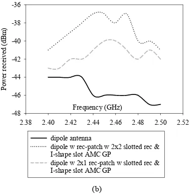
and 926 MHz and Fig. 12(b) shows the power received with and without AMC-GP at frequency range between 2.38 and 2.58 GHz. The finding suggests that the dipole antenna with AMC GP produces a higher received power than the dipole antenna with the absence of AMC GP. Moreover, the dipole antenna with more unit cells received more power than the dipole antenna with fewer cells. Longer measured reading distance of UHF and MWF meandered dipole tag is obtained too with more unit cells.
(a)
dipole antenna w 2x1 rec-patch w slotted rec & I-shaped slot AMC GP
dipole antenna w 2x2 rec-patch w slotted rec & I-shaped slot AMC GP
(b)
Fig. 11. (a)The fabricated multi-band dipole antenna with2x2 rectangular-patch with slotted rectangular and I-shaped slot AMC GP and (b) the measured return loss of the multi-band meandered dipole antenna with dual-band AMC-HIS GPs.
Frequency (MHz)
914 916 918 920 922 924 926
P
triple-band meandered dipole antenna dipole antenna w 2x1 rec-patch w slotted rec dipole antenna w 2x2 rec-patch w slotted rec
(a)
Frequency (GHz)
2.38 2.40 2.42 2.44 2.46 2.48 2.50 2.52
P
dipole w rec-patch w 2x2 slotted rec & I-shape slot AMC GP
dipole w 2x1 rec-patch w slotted rec & I-shape slot AMC GP
(b)
Fig. 12. The measured power received by the multi-band mean-dered dipole antenna with and without AMC GPs at the: (a) first band and (b) second band of the dipole antenna.
Table 6 summarizes the reading distance of the dipole tag antenna with 2 x 1 and 2 x2 slotted rectangular with I- shaped slot AMC-GP using two different RFID systems which operate at 920 MHz and 2.45 GHz.
2x1
rectangular-patch with slotted rectangular and -shaped slot AMC
2x2 rectangular-patch with slotted rectangular and -shaped slot AMC Measured reading
distance of UHF dipole tag antenna
6.00 m 8.00 m
Measured reading distance of MWF dipole tag antenna
0.9 m 1.25 m
Tab. 6. The measured reading distance of UHF and MWF meandered dipole tag antenna with dual-band AMC GPs.
5.
Conclusion
Acknowledgements
The authors thank the Ministry of Higher Education (MOHE) for supporting the research work, Research Man-agement Centre (RMC), School of Postgraduate (SPS) and Radio Communication Engineering Department (RACeD) Universiti Teknologi Malaysia (UTM) for the support of the research under grant no QJ13000.7123.02H02 and 4L008.
References
[1] SYDANHEIMO, L., UKKONEN, L., KIVIKOSKI, M. Effect of size and shape of metallic objects on performance of passive Radio Frequency Identification. International Journal Manufacturing Technology, 2006, vol. 30, no. 9-10, p. 897-905.
[2] UKKONEN, L., SYDANHEIMO, L., KIVIKOSKI, M. Patch antenna with EBG ground plane and two-layer substrate for passive RFID of metallic objects.In Proc. 2004 IEEE AP-S. 2004, vol. 1, p. 93-96.
[3] UKKONEN, L., SYDANHEIMO, L., KIVIKOSKI, M. Effects of metallic plate size on the performance of microstrip patch-type tag antennas for passive RFID. IEEE Antennas and Wireless Propagation Letters, 2005, vol. 4, p. 410-413.
[4] GOPINATH GAMPALA, ROHIT SAMMETA, REDDY C. J. A thin, low profile antenna using a novel high impedance ground plane. Microwave Journal, July 2010, vol. 53, no. 7, p. 70, -78.
[5] WONKYU CHOI, JEONG-SEOK KIM, JI-HOON BAE, GIL-YOUNG CHOI, CHEOL-SIG PYO, JONG-SUK CHAE. RFID tag antenna coupled by shorted microstrip line for metallic surfaces. ETRI Journal, August 2008, vol. 30, no. 4, p. 597-598.
[6] KOVACS, P., RAIDA, Z., MARTINEZ VAZQUEZ, M. Paramet-ric study of mushroom like and planar periodic structures in terms of simultaneous AMC and EBG properties. Radioengineering, De-cember 2008, vol. 17, no. 4, p. 19-24.
[7] SIEVENPIPER, D. F. High-impedance Electromagnetic Surfaces, PhD Thesis, University of California at Los Angeles, p. 39-44, 1999.
[8] FAN YANG, RAHMAT SAMII Electromagnetic Band Gap Structures in Antenna Engineering. Cambridge University Press, p. 156–201, 2009.
[9] SOHN, J. R., KIM, K. Y., TAE, H.-S. Comparative study on various Artificial Magnetic Conductors for low-profile antenna. Progress In Electromagnetic Research, PIER 61, 2006, p. 27–37.
[10] SIM, DONG-UK, CHOI, HYUNG-DO, KWON, JONG-HWA KIM, KIM, DONG-HO, CHOI, JAE-ICK. Dipole tag antenna structure mountable on metallic objects using Artificial Magnetic Conductor for wireless identification and wireless identification system using the dipole tag antenna structure. United States Patent, 20100007569, January 2010.
[11] DE COS, M. E., LAS HERAS, F., FRANCO, M. Design of planar Artificial Magnetic Conductor ground plane using Frequency Selective Surface for frequencies below 1 GHz. IEEE Antennas and Wireless Propagation Letters, 2009, vol. 8, p. 951-954.
[12] DE COS, M. E., ALVAREZ LOPEZ, Y., HADARIG, R. C., LAS-HERAS ANDRES, F. Flexible uniplanar Artificial Magnetic
Conductor. Progress In Electromagnetics Research, PIER 106, 2010, p 349-362.
[13] REA, S. P., LINTON, D., ORR, E., MCCONELL, J. Broadband high-impedance surface design for aircraft HIRF protection. IEE Proc.-Microw. Antennas Propagation, August 2006, vol. 153, no. 4, p. 307 – 313.
[14] XIE, H.-H, JIAO, Y.-C., SONG, K., ZHANG, Z. A novel multi-band electromagnetic multi-bandgap structure. Progress In Electromag-netics Research Letters, 2009, vol. 9, p 67–74.
[15] JOHN, M., AMMANN, M. J. Integrated antenna for multiband multi-national wireless combined with GSM1800/PCS1900/ IMT2000 + Extension. Microwave and Optical Technology Letters, March 2006, vol. 48, no. 3, p. 613- 615.
[16] ABU, M., RAHIM,M. K.A., AYOP, O., ZUBIR, F. Triple-band printed dipole antenna with single-band AMC-HIS. Progress In Electromagnetics Research B, PIER B 20, 2010, p. 225-244.
[17] ZHI NENG CHEN Antenna for Portable Device. John Wiley & Sons, p. 71-72, 2007.
About Authors ...
Maisarah ABU was born in Malacca, Malaysia on 10th
November, 1977. She received her B.Sc. in Electrical En-gineering from Universiti Teknologi MARA (UiTM) in 2000 and Master of Engineering in Electrical (Computer and Communication) from Universiti Kebangsaan Malay-sia (UKM) in 2003. She obtained her PhD from Universiti Teknologi Malaysia (UTM) in 2012. Her research interests are in the area of antennas and propagation, RFID and artificial magnetic conductor (AMC).
Mohamad Kamal A. RAHIM was born in Alor Star