i
MAILBOX INTEGRATED WITH GSM
MOHD SHAZWAN BIN SUHAIMI
This report is submitted in partial fulfillment of the requirements for the award of Bachelor of Electronic Engineering (Industrial Electronics) With Honours
Faculty of Electronic and Computer Engineering Universiti Teknikal Malaysia Melaka
ii
UNIVERSTI TEKNIKAL MALAYSIA MELAKA
FAKULTI KEJURUTERAAN ELEKTRONIK DAN KEJURUTERAAN KOMPUTER
BORANG PENGESAHAN STATUS LAPORAN PROJEK SARJANA MUDA II
Tajuk Projek : MAILBOX INTEGRATED WITH GSM
Sesi
Pengajian : 2011/2012
Saya MOHD SHAZWAN BIN SUHAIMI
mengaku membenarkan Laporan Projek Sarjana Muda ini disimpan di Perpustakaan dengan syarat-syarat kegunaan seperti berikut:
1. Laporan adalah hakmilik Universiti Teknikal Malaysia Melaka.
2. Perpustakaan dibenarkan membuat salinan untuk tujuan pengajian sahaja.
3. Perpustakaan dibenarkan membuat salinan laporan ini sebagai bahan pertukaran antara institusi pengajian tinggi.
4. Sila tandakan ( √ ) :
SULIT* (Mengandungi maklumat yang berdarjah keselamatan atau kepentingan Malaysia seperti yang termaktub di dalam AKTA RAHSIA RASMI 1972)
TERHAD* (Mengandungi maklumat terhad yang telah ditentukan oleh organisasi/badan di mana penyelidikan dijalankan)
TIDAK TERHAD
Disahkan oleh:
__________________________ ___________________________________
(TANDATANGAN PENULIS) (COP DAN TANDATANGAN PENYELIA)
Alamat :C193,JENGKA 7, BANDAR PUSAT
JENGKA, 26410 BANDAR JENGKA, PAHANG.
Tarikh: 14 JUNE 2012 Tarikh:
iii
“I hereby declare that this report is the result of my own work except for quotes as cited in the reference”
iv
“I hereby declare that I have read this report and in my opinion this report is sufficient in terms scope and quality for the award of Bachelor of Electronic Engineering (Industrial
Electronics) With Honours”
Signature : ………
Name : NUR FATIHAH BINTI AZMI
v
Special dedication to my beloved parents, Suhaimi Bin Ismail and Halimatul Saadiah Binti Abd. Rahman, my entire siblings, my friends Nurul Hanis Binti Shahbudin, Asyraf Bin Abd Razak, Mohd Shaufy Bin Suhaimi, all my dearest friends and my kind
vi
ACKNOWLEDGEMENTS
Special thanks to my supervisor, Mrs. Nur Fatihah Binti Azmi for his support, idea, knowledge and sharing his experience to fulfill the objective of this final year project. With his support I gain knowledge from this project. I have learned a lot of project management skill which include the time and cost effective to realize the project.
Also thanks to my friend for spending their time teaching me about the PIC controller connection and teaching me about Proteus software, which seems to be very difficult for me to understand before. Million thanks to all my friends that giving me so much supports to obtain the output of this project.
vii
ABSTRACT
viii
ABSTRAK
ix
CONTENTS
CHAPTER TITLE PAGES
PROJECT TITLE i
DECLARATION FORM DECLARATION
ii iii
SUPERVISOR DECLARATION iv
DEDICATION v
ACKNOWLEDGEMENT vi
ABSTRACT ABSTRAK
vii viii
CONTENTS ix
TABLE LIST xii
FIGURE LIST xiii
ABBREVIATIONS LIST xv
APPENDIX LIST xv
I INTRODUCTION
1.1 Introduction of the project 1
1.2 Problem statement 2
1.3 Objective of Final Year Project 3
x
1.5 Scope of Project 4
1.6 Comparison between conventional GSM Mailbox system with GSM Mailbox
4
1.7 Advantages and Benefits of the Mailbox Integrated With GSM
5
1.8 Project Basic operation 5
II LITERATURE REVIEW
2.1 Voltage regulator module
2.1.1 Advantages of the LM7805 series ICs 2.1.2 Disadvantages of the LM7805 series ICs
6 7 8
2.2 LM324 9
2.3 RS-232
2.3.1 RS-232 Waveforms
10 10 2.4 RS-232 Level Converters Driver/ Receiver – MAX 232 12
2.5 Short Message Services (SMS) 14
2.6 GSM Modem 15
III PROJECT METHODOLOGY
3.1 Phase 1 - Preliminary Investigation 19
3.2 Phase 2 – Analysis 19
xi
3.4 Software Development Process 3.5 Phase 4 – Implementation
3.6 Phase 5 - Maintenance and Testing
21 22 23
..00
IV CIRCUIT OPERATION
4.1 General Description
24
4.2 Introduction to SK-40 B 26
4.3 Low Power Quad Operational Amplifiers (LM324) 4.3.1 General Description
4.3.2 Unique Characteristics 4.3.3 Advantages 4.3.4 Features 27 27 28 28 28
4.4 PIC microcontroller 29
4.5 IR Sensor (IR receiver and IR transmitter) 4.6 MAX 232 – Level Converter
4.7 LED
4.8 Proteus Design Suite 7 4.9 PICkit2Programmer
4.10 USB ICSP PIC Programmers
31 32 34 35 36 37
V RESULTS AND DISCUSSION
5.1 Results
5.1.1 Proteus simulation results
38 40
xii
TABLE LIST
TABLE TITLE PAGES
1.1 Comparison between conventional GSM Mailbox system
with GSM Mailbox
4
2.1 4.1 4.2
Table lists of the AT commands
Types and size of letters
Table of RS232 Line Type and Logic Level
17 25 33
5.1 Hardware Results 39
5.3 Discussion
5.3.1 Hardware Development
5.3.2 Software Programming (PIC microcontroller)
54 54 54
VI CONCLUSSION AND RECOMMENDATION
6.0 Introduction 6.1 Conclusion
56 56 6.2 Problem and Limitation
6.3 Recommendation
57 57
REFERENCES 58
xiii
FIGURE LIST
FIGURE TITLE PAGES
2.1 The Voltage Regulator System 6
2.2 LM324 IC 9
2.3 Interfacing Devices to RS-232 Ports 10
2.4 TTL/CMOS Serial Logic Waveform 10
2.5 RS 232 Waveform 11
2.6 RS-232 Logic Waveform 12
2.7 Pin Out For the MAX-232, RS-232 Driver/Receiver 13
2.8 Typical MAX – 232 Circuits 13
2.9 GSM Wavecom MODEM 16
3.1 3.2
Design phase
Flow chart on project development
18 19
3.3 Software Development Process 21
3.4 4.1
USB to RS232 cable converter Block diagram of the system
22 25
4.2 SK-40B 27
4.3 LM324 connection diagram 29
4.4 PIC Micro controller 30
4.5 Comparison Type of PIC 31
4.6 Analog infrared sensor 31
4.7 MAX 232 Connections 32
4.8 LED light 34
4.9 Proteus Design Suite 7 35
xiv
4.11 USB ICSP PIC Programmer 37
4.12 UIC-S Socket Board 37
5.1 Starting system 40
5.2 The system after confirm button is pressed 41
5.3 Output virtual terminal 41
5.4 Two IR sensors signal is block by the letter 42
5.5 Output virtual terminal 43
5.6 After the letter passing through two IR sensors 43
5.7 Output virtual terminal 44
5.8 After the letter passing through three IR sensors 45
5.9 Output virtual terminal 45
5.10 After the letter passing through four IR sensors 46
5.11 Output virtual terminal 46
5.12 IR when its signal is block 47
5.13 IR when its signal is receive by receiver 47
5.14 The GSM Mailbox hardware front view 48
5.15 The GSM Mailbox hardware back view. 49
5.16 LCD display for set the number phone 49
5.17 One of IR sensor detect 50
5.18 LCD display the current letter in mailbox 50
5.19 Two of IR sensor detects 51
5.20 LCD display the current letter in mailbox 51
5.21 Status report get by mobile phone 52
5.22 Three of IR sensor detects 52
5.23 LCD display the current letter in mailbox 52
5.24 Status report get by mobile phone 53
5.25 Four of IR sensor detects 53
5.26 LCD display the current letter in mailbox 53
5.27 Status report get by mobile phone 54
xv
LIST OF ABBREVIATIONS
PCB - Printed Circuit Board RF - Radio Frequency
Rx - Receiver
Tx - Transmitter
IC - Integrated Circuit DC - Direct Current
AC - Alternate Current
LED - Light Emitting Diode ADC - Analog Digital Converter
I/O - Input/ Output
RAM - Random Access Memory
EEPROM - Electrically Erasable Programmable Read-Only Memory PIC - Peripheral Interface Controller
PSM - Projek Sarjana Muda FYP - Final Year Project Vcc - Collector voltage
VGND - Ground Voltage
GSM - Global System for Mobile Communication SMS - Short Messaging Service
RISC - Reduced Instruction Set Computing
xvi
APPENDIX LIST
APPENDIX TITLE PAGES
A.1 PIC16F877 Datasheet 60
A.2 Wavecom GSM Modem kit 61
CHAPTER I
INTRODUCTION
This chapter will discuss a brief about the introduction of the project. Where, it state about the purpose of the project, objective, scope of work, problem statement and advantage acquire from the project.
1.1 Introduction of the project
Some people mailbox is very important to them. They works depend on the customer mail. For example, lawyer, banker, online business and writer they need feedback letter from their client as their backbone to move forward and to ensure their business going well. Also some of country they have a mail robbery issues either their mail has been stolen or their mail post box been smashed.
2 previous technologies in that both signaling and speech channels are digital, and thus GSM considered a second-generation (2G) mobile phone system. This also facilitates the widespread implementation of data communication applications into the system.
This project is mainly about a system based on real monitoring to ensure the mail is arriving at home. The Smart Mail Box is a normal mailbox with a system where it will automatically inform the owner of the house that they got a mail at home. The Smart Mail Box will leave a message via (SMS) short message system to the number that been registered.
A sensor from one point to the next point will touch to each other to trace the mail. Once the mail cut of the laser, the system will send short message system (SMS) via GSM to the number that have been recorded to the system. Therefore, the owner will automatically notify that they got a mail at home, office or etc. The system also sending information about the letter size which are small, medium and large. Small letter is size from 5.5 cm to 11 cm. While medium size is 12 cm to 16.5 cm and the larger letter is around 17 cm to 22 cm.
1.2 Problem statement
Below show the problem possibilities occur without the GSM Mailbox System:
Inability of the user to know each mail and packages arrive in their mailbox.
3 1.3 Objective of Final Year Project
The project will be carried out during the final year. In this project, we will work individually with a supervision of their respective department academic members.
The aim of FYP is to provide the opportunity for student to apply and integrate the theoretical knowledge and principles taught in the course in solving technical problems. It also provides the opportunity for the students to demonstrate independence and originality, as well as to plan and organize project over a certain period of time. The main objectives of the course are to:
1. Document all findings and problem encountered
2. Apply practical hands-on techniques in process, quality control and related analysis in their specialized program.
3. Demonstrate the procedures and methods of project implementation
4. Execute the sequence in various steps required to produce/ manufacture/ test/ solve/ improve the real life industrial projects problem.
5. Analyze findings and results of the project.
6. Produce a technical report and make a presentation.
1.4 Objectives
The aim of the work is to investigate and to design the Smart Mail Box via GSM. In doing so, the bulk of the work can be summarizing as follows:
To build a Mailbox integrated with GSM network.
To create detection system that aims to detect the mail that arrives in the mailbox.
4 1.5 Scope of Project
Transceiver (Tx) Data for Smart Mail Box via GSM is an innovation of monitoring the mail in the office or house. The scopes of this project consist of hardware and software. The basic idea is to monitoring software and the main part of the hardware is the keypad, RF wireless and sensor system.
The three level sensor components consist to transmit data through monitoring system. The main processor that controls the whole system is PIC16F877A. Upon this project to be monitor, the data will be transmit and receive through Radio Frequency (RF) to the next processor. The data will then be process to monitor tank level into computer system and record the total condition level.
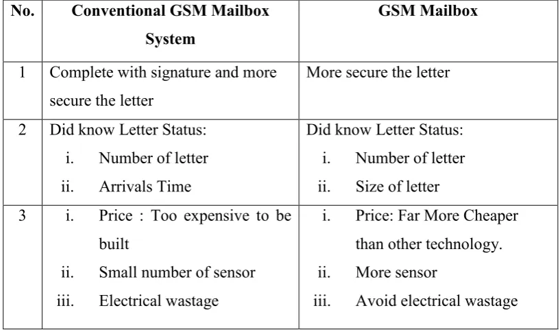
1.6 Comparison between conventional GSM Mailbox system with GSM Mailbox.
Table 1.1: Comparison between conventional GSM Mailbox system with GSM Mailbox.
No. Conventional GSM Mailbox System
GSM Mailbox
1 Complete with signature and more secure the letter
More secure the letter
2 Did know Letter Status: i. Number of letter ii. Arrivals Time
Did know Letter Status: i. Number of letter ii. Size of letter 3 i. Price : Too expensive to be
built
ii. Small number of sensor iii. Electrical wastage
i. Price: Far More Cheaper than other technology. ii. More sensor
5 1.7 Advantages and Benefits of the Mailbox Integrated With GSM
Notify the letter status to their mobile.
User can know the arrival time and the total letter in their mailbox. Notify the size of the letter. (small, medium and large categories)
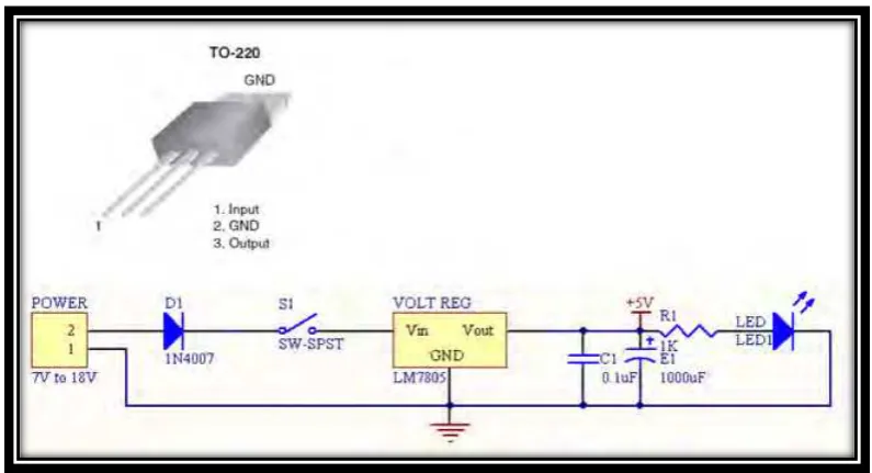
1.8 Project Basic operation
The Smart mailbox via GSM is operating using 7V adapter. The supply 7V will convert to 5V through Voltage regulator LM7805 to generate the Microcontroller PIC PIC16F877A and 7V to GSM through RS 232 level converter driver or receiver MAX 232.
CHAPTER II
LITERATURE REVIEW
In this chapter, it will discuss about the literature review which it contains the information gathered to gain knowledge and ideas in completing the project. There are several sources that have been taken as a resource such as books, thesis, journal and website.
It was included the operation of the circuit, the hardware and software which is useful in the project.
2.1 Voltage regulator module
7 The voltage regulator module is used to protect PIC and other connected sensors / actuators from over voltage. This is because PIC and all other connected sensors, actuators all support 5V DC only. Over voltage will cause any of the module burn.
LM7805 is used to regulate voltage in the system and output 5V DC (max output current: 1000mA). It supports input voltage from 7V DC to 18V DC. If the input voltage is over, the LM7805 will burn or auto shutdown due to overheat. The generated 5V from LM7805 will be noise filtered by 0.1uF ceramic capacitor and a 1000uF electrolytic capacitor. This is to avoid high frequency oscillation on the outputs which may cause system hang or unstable.
A diode is connected at the input of the LM7805. This is to avoid voltage connected reversely. An on/off switch is used to turn on/off the system and a LED (5V, 5mA) is used to indicate the system is power on/off. The LED is connected through 1KR resistor to limit current pass through LED is 5mA.
2.1.1 Advantages of the LM7805 series ICs
The 7805 series has several key advantages over many other voltage regulator circuits which have resulted in its popularity:
8 78xx series ICs have built-in protection against a circuit drawing too much power. They also have protection against overheating and short-circuits, making them quite robust in most applications. In some cases, the current-limiting features of the 78xx devices can provide protection not only for the 78xx itself, but also for other parts of the circuit it is used in, preventing other components from being damaged as well.
2.1.2 Disadvantages of the LM7805 series ICs
The input voltage must always be higher than the output voltage by some minimum amount (typically 2 volts). This can make these devices unsuitable for powering some devices from certain types of power sources (for example, powering a circuit which requires 5 volts using 6-volt batteries will not work using a 7805).
As they are based on a linear regulator design, the input current required is always the same as the output current. As the input voltage must always be higher than the output voltage, this means that the total power (voltage multiplied by current) going into the 78xx will be more than the output power provided. The extra input power is dissipated as heat. This means both that for some applications an adequate heat sink must be provided, and also that a (often substantial) portion of the input power is wasted during the process, rendering them less efficient than some other types of power supplies. When the input voltage is significantly higher than the regulated output voltage (for example, powering a 7805 using a 24 volt power source), this inefficiency can be a significant issue.