i
MAILBOX INDICATOR WITH REMOTE SWITCH
MOHAMAD SHARIFUDDIN BIN EZHAM
This report is submitted in partial fulfillment of the requirements for the award of Bachelor of Electronic Engineering (Telecommunication Electronics) With Honours
Faculty of Electronic and Computer Engineering
Universiti Teknikal Malaysia Melaka
ii
Tajuk Projek : MAILBOX INDICATOR WITH REMOTE SWITCH
Sesi
Pengajian : 2008/2009
Saya MOHAMAD SHARIFUDDIN BIN EZHAM mengaku membenarkan Laporan Projek Sarjana Muda ini disimpan di Perpustakaan dengan syarat-syarat kegunaan seperti berikut:
1. Laporan adalah hakmilik Universiti Teknikal Malaysia Melaka.
2. Perpustakaan dibenarkan membuat salinan untuk tujuan pengajian sahaja.
3. Perpustakaan dibenarkan membuat salinan laporan ini sebagai bahan pertukaran antara institusi
pengajian tinggi.
4. Sila tandakan ( √ ) :
SULIT*
(Mengandungi maklumat yang berdarjah keselamatan atau kepentingan Malaysia seperti yang termaktub di dalam AKTA RAHSIA RASMI 1972)
TERHAD* (Mengandungi maklumat terhad yang telah ditentukan oleh organisasi/badan di mana penyelidikan dijalankan)
TIDAK TERHAD
Disahkan oleh:
__________________________ ___________________________________
(TANDATANGAN PENULIS) (COP DAN TANDATANGAN PENYELIA)
iii
“I hereby declare that this report is result of my own work except for quotes as cited in the references.”
Signature : ……….
iv
“I hereby declare that I have read this thesis and in my opinion, it is sufficient in terms of the scope and quality for the award of Bachelor of Electronic Engineering
(Telecommunication Electronics) With Honour”
Signature : ………
Name : ZULHAIRI BIN OTHMAN
v
ACKNOWLEDGEMENT
I would like to acknowledge a few people that help me in achieving this goal and coming out joyfully. I would like to thank my supervisor, Mr. Zulhairi Othman for guiding me and helping during the course of design works. I would also like to thanks the management of the PSM Laboratory for providing me with whatever facility I had utilize for completion of this design. All thanks due especially to my family members, my father, Ezham Bin Shariff, my mother, Najihah Binti Bakar, my sister and my brother for their prayer and inspiration which has help me in
becoming what I‟m today. And lastly to all my friends who have been a pillar
support during the arduous to complete this project. It‟s a bond that I will cherish all through my life.
vi
ABSTRACT
vii
ABSTRAK
viii
CONTENTS
CHAPTER TITLE PAGE
PROJECT TITLE i
APPROVAL REPORT STATUS FORM ii
DECLARATION iii
SUPERVISOR DECLARATION iv
ACKNOWLEDGEMENT v
ABSTRACT vi
ABSTRAK vii
CONTENTS viii
LIST OF TABLES xii
LIST OF FIGURES xiii
I INTRODUCTION
1.1 Overview 1
1.2 Problem Statement 2
1.3 Project Objectives 2
1.4 Scope of Works 3
ix 2.4.1 Operation of Microprocessor 16 2.4.1.1 Function of each block 17
x
3.4.1 Microcontroller 27 3.4.2 I/O Port for IC AT89C2051 28 3.5 Development of Programming Language 29
3.5.1 Assembly Language (ASM) 30
IV METHODOLOGY OF THE PROJECT
4.1 Introduction 31
4.4 Simulation and Hardware testing 36
xi
5.2.2 Fabrication process 49
5.2.2.1 Design the mailbox 53
5.3. Circuit Analysis 54
5.3.1 Analysis on main circuits 54 5.3.2 Analysis between main circuit and remote
control circuit 55
5.3.3 Analysis on remote control circuit 57
VI DISCUSSION AND CONCLUSION
6.1 CONCLUSION 60
6.2 SUGGESTION 61
xii
LIST OF TABLES
NO TITLE PAGE
2.1 Relationship between operating mode 13 and load status for diffuse scan
2.2 Diffuse Scan Correction Factor 14 2.3 Pin configuration for AT89C2051 16
3.1 I/O port for AT89C2051 29
5.1 Output Voltage at main circuit 54
5.2 Output voltage when Data out from remote was connect directly to the input pin14
HT 12D 56
xiii
LIST OF FIGURES
NO TITLE PAGE
2.1 A typical RC signal transmission 7
2.2 Thru beam technique . 10
2.3 When it is in Dark operate 13
2.4 When it is in Light operate. 13
2.5 Pins configuration of AT89C2051 15
2.6 Operation Flow of Microprocessor 16
2.7 74LS04 and its structure 19
2.8 Logic circuit in 74LS04 19
2.9 ULN2003 structure 20
2.10 Schematic for each Darlington pair 21
2.11 4 pins relay 21
2.12 Operation of the relay 22
2.13 5 pin relay 22
3.1 Operation of thru beam sensor 26
3.2 Effective beam 27
xiv
4.1 Flow Chart of the Methodology 32
5.1 Hex file after convert from the file.asm 42 5.2 Coding that I load in the AT89C2051 and file.hex 43
5.3 Flow chart of the program 44
5.4 Simulation on Proteus 45
5.5 Lisa Partition Analyzer Errors 45
5.6 Project Testing on project board 46
5.7 Reference circuit for transmitter circuit
(Hand Held remote control) 48
5.8 Reference circuit for receiver circuit (at the Mailbox) 48
5.9 Voltage regulators (5 volts) 49
5.10 Normal schematic circuit (Main Circuit) 49 5.11 PCB layout after transform (Main Circuit) 50 5.12 Normal schematic circuits (Remote Control Circuit) 50 5.13 PCB layouts after transform (Remote Control Circuit) 51 5.14 Layout when we print using Microsoft word 51
5.15 Complete circuit designs 53
5.16 Connection between remote circuits to the main circuit 55
5.17 Pin 17 (HT12D) testing 57
1
CHAPTER 1
INTRODUCTION
1.1 Overview
This final year project report is all about how to design, implement and test an electronic letterbox/ mailbox that will indicate the box status if it is triggered by a remote control as far as 10 meters from the target (mailbox). When we triggered by a remote control it will send radio frequency through the transmitter to the receiver at the mailbox. Here the signal which contains data will be processed and translated using Programmable Integrated Circuit. To sense things in the box sensor will be used. When the sensor senses letters or flyers it will send back a signal to indicate that mailbox was occupied. The indicator should be small enough to fit inside a typical mailbox and can detect the existence of letter or papers such as notices and flyers. Its indicator will be visible through the transparent window.
2
1.2 Problem Statement
The purpose of developing this project was to upgrade the function of the mailbox. Before this the user need to walk to the mailbox to check whether there are letters inside. They have wasting their time and energy to walk to the mailbox if there are no letter or others thing like note and flyer. If there is a device that can be used to indicate the status of the mailbox, the user does not have to waste their time and energy anymore.
1.3 Project Objectives
In developing this project we have determined a few of objectives that we have to archive at the end of this project. This objective was create as a guide line to archive the purpose of developing electronic mailbox. We have consider a few things before determine the suitable objective for this project. All of the objectives relate to the problem faced by the user and the work procedure that we will undergone when developing this project.
In our first objectives is to design electronic mailbox indicator that would show the box status empty or occupied. This first objective is our main objectives.
Our second objective is to implement the concept of transmission signal and develop own program for its controller.
3
1.4 Scope of Work
Scope of work is a guide line for our project. We have to archive all the target for each of the scope. Each of the scope is related to the operation of the system. Our scope consist 4 major parts that will play a main role in the system operation. There are sensor, transmission signal, indicator and controller.
Our first scope is about a sensor. Sensor should be able to detect the small white envelope in the mailbox. This is our main target that we have to archive for the ability of the sensor to sense object.
Our second scope is about the signal transmission. For our scope the transmitter and receiver should be able to transmit and received signal from 10 meter. This is a maximum range for the user to transmit signal using remote switch from the mailbox.
For our third scope is about the indicator. Our minimum specification required LEDs as a device that will be display the indication at the transparent window of the mailbox.
In our last scope microprocessor must be able to control the operation of the system by following the command program. Microprocessor will control sensor operation, translate data, and control the indicator.
1.5 Methodology
4
CHAPTER 2
BACKGROUND STUDY
2.1 Introduction
In this final year project I have to design the electronic mailbox and remote control. So I have to fabricate for those thing. Before doing the fabrication process I have to identify the theory that I will apply in designing the operation circuit for the system. After understand the theory I have to design circuit by using electronic software. I also have undergone one workshop that was organized by the Faculty of Electronic and Computer Engineering. This workshop is all about the programmable integrated circuit. I have gained my knowledge through this workshop in application of PIC. PIC is one of the main parts that will be organizing all the application for my project.
5 will involve two or more parties which react as a receiver to receive the data. There are two types of signal transmission that I have identified. There are analog and digital transmissions. For this project I have decide to apply the theory of digital transmission. As from the above definition digital signal will involve other parties as a receiver or transmitter. From the theory transmission signal will be modified to carry the transmitted information. Nowadays we see a lot of application from this concept. Example that we can take is in the microwave system which the carrier of radio frequency is in analog signal but its modulated information was in digital signal.
2.2.1 Data Transmission
6
2.2.2 Remote Control
In the data transmission there are two ways or method to transmit data. There are parallel and serial transmissions. From the research under this topic serial transmission is the sequential transmission of signal element of a group which representing a character or other entity of data. Like from previous explanation digital serial transmissions are bits sent over a networking channel path sequentially. For this project networking channel mean air as a medium of transmission line which will be in frequency parameters. Serial transmission does not require lot of signal processing and it is less chance of error. Other advantage of serial transmission is the transfer rate of each individual path may be faster. For this electronic mail box, it does not have many operations to work with. It is only triggered to detect the paper especially letter. We are not going to involve with parallel transmission because we will not apply this concept in developing this electronic mailbox.
In designing the remote control we have to determine the types of remote control that we going to use. By following the information that we gathered there are two types of remote control in the market and there are radio frequency and infrared remote control. I have decided to use radio frequency as my hand held remote control for my final year project. Definition of the radio frequency or know as RF is oscillation rate which it is in the range of 3 Hz to 300 GHz. Alternating current electrical signal will depends on this range of frequency to detect and provide the radio waves. The radio frequency refers to oscillations in electromagnetic radiation.
Suitable radio frequency range was determined. I will applied ultra high frequency which it range start from 300 Hz to 3000MHz. This range of frequencies is suitable for remote control usage.
7
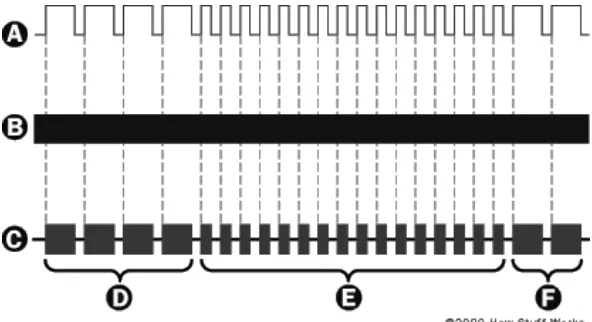
In the real application of remote control we can see how they applied the concept of RF on the radio control device. Let assume that the frequency used for one device is at 27.9 MHz. Below are how radio control its circuit:
1. You press a trigger button.
2. The trigger causes a pair of electrical contacts to touch, completing a circuit connected to a specific pin of an integrated circuit (IC).
3. The completed circuit causes the transmitter to transmit a set sequence of electrical pulses.
Each electrical sequence contains a short group of synchronization pulses, followed by the pulse sequence. For the operation of this device, the synchronization segment which alerts the receiver to incoming information is four pulses that are 2.1 milliseconds long, with 700-microsecond intervals. The pulse segment, which tells the antenna what the new information is, uses 700-microsecond pulses with 700-microsecond intervals.
8
Below are meaning of each pulse sequence that will be used in the pulse segment:
Forward: 16 pulses MHz. The signal is then converted back into an electrical pulse sequence.
6. The pulse sequence will be decodes that sequence and starts it certain function.
2.3 Sensor
Sensor is other important part for the project to operate. First of all I have to understand the operation concept of a sensor. After doing some research and study on this part I found that sensor is equipment that does measurement on the physical quality and the result can be seen by the observer and instrument. Nowadays application of the sensor has been widely use. Normally we can find sensor applied into the factory machine and robotic works. The sensitivity of one sensor can be determined by seeing how much the sensor output change by varying the measured quantity changes. So we say that a highly sensitive sensor is a sensor that can measure small change happen during measurement process.
9
letter will be the main target. From the observation the most common sensor that have been used in the factory sector is photoelectric sensor, vision sensor and vision systems. Functions for every type of sensor are:
Detection
Synchronization
Inspection
Detect classification / optical character verification
The functions above are defined in more detail below:
1. Detection: Sense an object that reached or cross a define reference point. 2. Synchronization: Tell where the object is at a certain point.
3. Inspection: Determine whether the object satisfied certain criteria.
4. Machine Vision: Guidance or alignment, precision measurement, complex defect detection and classification and output data for process control and traceability.
So, to determine type of sensor, firstly we have to decide type of output required for the design. I have decide to use photoelectric sensor because it is required a simple pass/ fail binary output indicating whether a target is present or not.
Photoelectric sensor is available for any sensing mode and performance levels and design to address a host of applications. The photoelectric sensor can detect color, opacity, shape size and reflective properties of the object. These entire requirements will determine the best sensor mode which can transmit beam, diffuse proximity and retroreflective. Most photoelectric sensors incorporate operator-selectable sensitivity to establish a light intensity above or below which an output signal will be energized.
10
distance is also a factor in selecting a scan technique. Some techniques work well at greater distances while others work better when the target is closer to the sensor.
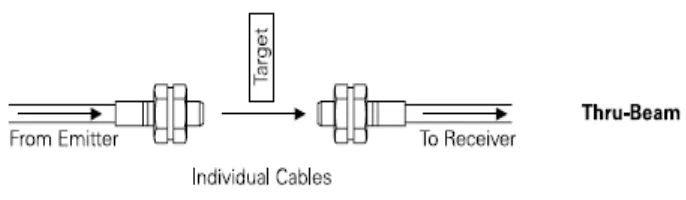
For this project I have decide to use thru beam technique. This technique has two sensors that emit light and the light will be received at another point which is a receiver. The sensor detects the interrupt when the emitting light does not reach at the receiver. For this project application, fault may occur when letter or other opaque medium cross the light beam of the sensor. Normally the part will need to have a highly repeatable position to be detected consistently. The shape, color, opacity and distance from the sensor and the angle of the target impact the effectiveness of the sensor to reliably detect these targets. Objects in the background also can be an issue if the sensor detects this object and also the desired target.
Figure 2.2 Thru beam technique.
A basic photoelectric sensor is a part detection device. The ability of the sensor is to look at one point and indicate whether a part is present or not. If the sensor is used as an inspection device, a single sensor is looking for a specific feature on a part. In order for the sensor to determine if the feature is present the application normally required:
The object is fixed in a highly repeatable position and orientation during the detection process.