International Journal of Energy and Power Engineering Research 1 (2013) 15-23
SIMULATION AND EXPERIMENTAL RESULTS OF SHUNT ACTIVE POWER FILTER
FOR HARMONICS REDUCTION BY USING pq-THEORY
Marizan Sulaiman, Ummi Imarah, Siti Farhana, Rosli Omar, Azhar Ahmad and Nur Hazahsha
Faculty of Electrical Engineering, Universiti Teknikal Malaysia Melaka,Karung Berkunci No. 1752, Durian Tunggal, 76109, Melaka. Email: [email protected]
ABSTRACT
This paper presents an instantaneous p-q Theory applied in shunt Active Power Filter (APF) to reduce the harmonics in power electrical system mainly in current waveform. The simulation by using Matlab/Simulink based on p-q Theory and the experimental results done in laboratory will be discussed. The results have shown a reduction of harmonics and an improvement of power quality at distribution feeders.
Keywords- Active power filters (APF), p-q Theory, Matlab/Simulink, and Total Harmonic Distortion (THD).
1. INTRODUCTION
In recent years, the increasing of harmonic pollution becomes a huge concern due to the proliferation of nonlinear loads consumed by industrial and end-users. Nonlinear device is which the current is not proportional with the applied voltage and most of them are fluorescence lighting, diode or thyristor rectifier, and uninterruptable power supplies (UPS). The existence of harmonics in system could cause greater losses, decrease the power factor and could result an operation failure as well (Watanabe et al. 2008)(Izhar et al. 2004).
Harmonic can be defined as an integral multiple of the fundamental frequency. It also could be understood as an additional waveform of frequency that is multiple form fundamental frequency. Power electrical system could be severely affected because of harmonics issue. In three-phase system with neutral, when each three-phases is fully loaded the combined fundamental current in neutral will be zero. However, the combined current for triplen harmonics (3rd, 9th, 15th) is added instead of cancel out for each other. Due to this problem, it can cause an extra heating to neutral conductor (Omar et al. 1990)(Ucar & Ozdemir 2008).
2. SHUNT ACTIVE POWER FILTER
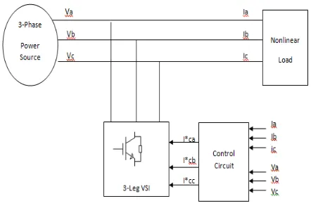
Several types of mitigation methods have been introduced over the years and one of the most effective methods is APF. Other method used is Passive Filter (PF) but due to some disadvantages (Lada et al. 2010), APF is widely chosen as a viable method to solve harmonics problem in power distribution system (Izhar et al. 2004)(Chen & Joos, 2000). Figure 1 shows the scheme for shunt APF in 3 phase system electrical distribution system.
Figure 1 Shunt APF in 3 phase system
3. p-q THEORY
1
1
1
2
2
2
.
.
3
3
3
0
2
2
a b cv
v
v
v
v
(1.1)
1
1
1
2
2
2
.
.
3
3
3
0
2
2
a b ci
i
i
i
i
(1.2)
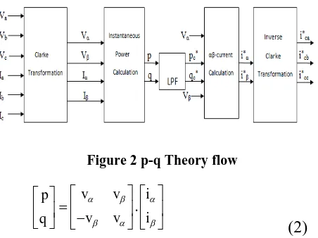
Figure 2 presents the flow for p-q Theory to compute the compensation current needed. The three phase voltage and current are transformed to αβ coordinates by using Clark Transformation. The instantaneous power calculation is accomplished using Eqn. (2).
Figure 2 p-q Theory flow
.
v
v
i
p
v
v
i
q
(2)
As seen in Eqn. (3.1) and (3.2), the real power, p, and the reactive power, q, are consist of two components which are dc and ac components,
̅ ̃ (3.1)
̅ ̃ (3.2)
where ̅ and ̅ are the dc components while ̃ and ̃ are the ac components.
For real power, p, only ̃ that need to compensated while for reactive power, both components will be compensated (Ciprian et al. 2011). This is due to ̅ is the solely component that used to transfer the energy from supply to loads among the four components. The other remaining
three components are simply the exchange energy between source and loads (Afonso et al. 2003).
Based on explanation above, the power that should be compensated, pc* and qc*, can be defined as shown in Eqn. (4.1) and (4.2). pc* and qc* can be selected through the designed filters (Watanabe et al. 2010). Then, the αβ -current is obtained from the compensated power by using Eqn. (5).
* c
p
p
(4.1)* c
q
q
q
(4.2)* *
2 2 *
*
1
.
cc
i
v
v
p
v
v
v
v
q
i
(5)
The compensation currents are computed through Inverse Clarke Transformation as shown in Eqn. (6) (Watanabe et al. 2008). The p-q Theory is relatively simple since its calculation only includes algebraic expressions that can be implemented using standard processors (Afonso et al. 2000). * * * * *
1
0
2
1
3
.
3
2
2
1
3
2
2
ca cb cc i i i i i
(6)
4. RESULTS
4.1 Simulation Results
4.1.1Without Active Power F ilter
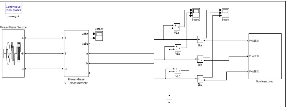
Figure 3 Simulation circuit without APF
Figure 4 Voltage and current waveform at supply
point Figure 6 Current THD at supply point 4.1.2 With Active Power Filter
Figure 6 shows the system that has been added by the shunt APF. The p-q Theory and hysteresis technique are used for the control circuit in order to calculate the current waveform that need to be compensated. Figure 7 shows the control circuit of the system where the amount of injected current is calculated by p-q Theory in order to implement the compensation process. The voltage and current waveform after the compensation is shown in Figure 8. The total harmonic distortion for voltage and current are reduced significantly as presented in Figure 9 and Figure 10.
connection with APF. A significant reduction of the total harmonic distortion can be observed.
Figure 7 Simulation circuit with APF
Figure 8 Control circuit for harmonics compensation
Table 1 Summary of THD for voltage and current for simulation results
Rectifier load (R=50Ω, L=100mH, C=5uF)
THDV (%) THDI (%)
Phase a Phase b Phase c Phase a Phase b Phase c
Without APF 0.37 0.57 0.55 33.36 36.93 35.86
Figure 9 Voltage and current waveform at supply point
Figure 10 Voltage THD at supply point
Figure 11 Current THD at supply point
4.2 Experimental Results
4.2.1Without Active Power Filter
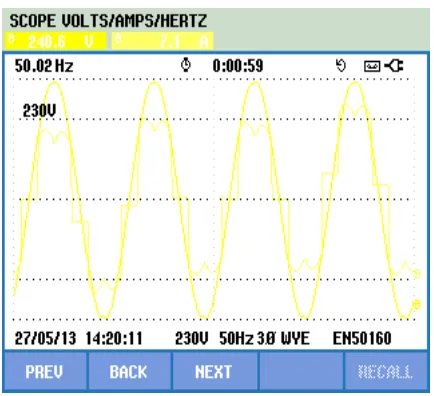
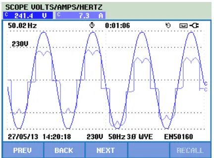
The experimental had been carried out in laboratory to observe the differences of waveform when the APF is connected and disconnected by using variable rectifier RL as a load. Figure 11 to 13 shows the distorted current waveform at supply point when APF is not connected.
i. Voltage and Current
Figure 12 Voltage and current waveform for phase a
Figure 13 Voltage and current waveform for phase b
Figure 14 Voltage and current waveform for phase c
ii. Current THD
Figure 15 THDI for phase a
Figure 16 THDI for phase b
iii. Voltage THD
Figure 18 THDV for phase a
Figure 20 THDV for phase c
4.2.2 With Active Power Filter
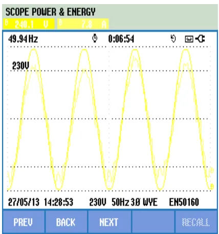
In order to correct the distorted current waveform at the supply point, APF was connected to the system. It can be seen that current waveform has been smoothly become sinusoidal. The corrected waveform can be seen in Figure 20, 21 and 22 for phase a, b and c respectively.
i. Voltage and Current
Figure 21 Voltage and current waveform for phase a
Figure 22 Voltage and current waveform for phase b
Figure 13 Voltage and current waveform for phase c
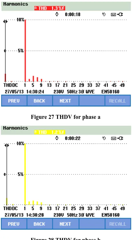
Figure 23, 24 and 25 show the THD for current for each phase while the THD for voltage spectrum can be seen in Figure 26, 27 and 28.
Figure 24 THDI for phase a
Figure 25 THDI for phase b
Figure 26 THDI for phase c
iii. Voltage THD
Figure 27 THDV for phase a
Figure 28 THDV for phase b
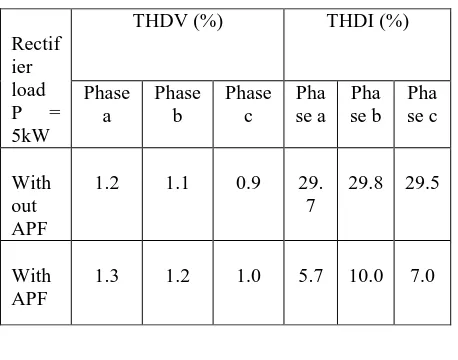
Table 2 shows the summary for experimental results for harmonic reduction. As seen, the value of THD for current is reduced significantly after APF connected to the system. As for THD for voltage do not have much difference between before and after as the percentage value is already low before the APF is connected.
Table 2: Summary of THD for voltage and current for experimental results
5. CONCLUSION
After the addition of APF at the source terminal, the THD of harmonic currents has been reduced significantly. The simulation results have shown excellent performance, while the experimental results have shown comparable performance to the simulation results. It can be concluded that the APF can be used to mitigate the harmonics currents in distribution feeders in order to enhance the best power quality in the distribution system.
ACKNOWLEDGEMENT
The authors wish to thank Universiti Teknikal Malaysia Melaka for its support through the grant MTUN/2012/UTeM-FKE/3 M00011.
REFERENCES
Afonso, J., Couto, C. & Martins, J., 2000. Active Filters with Control Based on the p-q Theory 47: 5–10. Afonso, J.L., Freitas, M.J.S. & Martins, J.S., 2003. p-q
Theory power components calculations, IEEE International Symposium on Industrial Electronics :385–390.
Chen, S. & Joos, G., 2000. Analysis and comparison of passive & active harmonic suppression filters in distribution systems, Canadian Conference on Electrical and Computer Engineering. Conference Proceedings. Navigating to a New Era 2 :615–619. Ciprian,B., Gelu,G., Toader, M., Grigore,F., 2011.
Comparison of Three Phase 4-leg Shunt Active Power Filter Algorithms: 8–10.
Izhar,M., Hadzer,C.M., Syafrudin,M., Taib,S., Idris,S., 2004. Performance for Passive and Active Power Filter in Reducing Harmonics in the Distribution System:104–108.
Omar, R., Ahmad, A., & Sulaiman, M., 1990. Triplen Harmonics Mitigation 3 Phase Four-Wire Electrical Distribution System Using Wye- Zig-Zag Transformers.
Lada,M.Y., Bugis,I., Talib,M.H.N., 2010. Simulation a
Shunt Active Power Filter using
MATLAB/Simulink:.23–24.
Ucar, M. & Ozdemir, E., 2008. Control of a 3-phase 4-leg active power filter under non-ideal mains voltage condition, Electric Power Systems Research, 78(1): 58–73.
Watanabe, E.H., Akagi, H., Aredes,M., 2008. Instantaneous p-q Power Theory for Compensating Nonsinusoidal Systems.
Watanabe, E.H., Aredes,M., Afonso,J.L., Pinto,J.G., Monteiro,L.F.C., Akagi,H., 2010. Instantaneous p– q power theory for control of compensators in micro-grids, International School on Nonsinusoidal Currents and Compensation: 17–26.
Rectif ier load
P =
5kW
THDV (%) THDI (%)
Phase a Phase b Phase c Pha se a Pha se b Pha se c With out APF
1.2 1.1 0.9 29.
7
29.8 29.5
With APF
