This content has been downloaded from IOPscience. Please scroll down to see the full text.
Download details:
IP Address: 103.26.74.254
This content was downloaded on 03/01/2014 at 04:05
Please note that terms and conditions apply.
Assessment on tracking error performance of Cascade P/PI,
NPID and N-Cascade controller for precise positioning of xy
table ballscrew drive system
L. Abdullah1, Z. Jamaludin, N.A. Rafan, J. Jamaludin, T.H. Chiew
Centre of Excellence, Advanced Manufacturing Centre, Faculty of Manufacturing Engineering, Universiti Teknikal Malaysia Melaka (UTeM), Hang Tuah Jaya, 76100 Durian Tunggal, Melaka, Malaysia
E-mail: [email protected]
Abstract. At present, positioning plants in machine tools are looking for high degree of accuracy and robustness attributes for the purpose of compensating various disturbance forces. The objective of this paper is to assess the tracking performance of Cascade P/PI, Nonlinear PID (NPID) and Nonlinear cascade (N-Cascade) controller with the existence of disturbance forces in the form of cutting forces. Cutting force characteristics at different cutting parameters; such as spindle speed rotations is analysed using Fast Fourier Transform. The tracking performance of a Nonlinear cascade controller in presence of these cutting forces is compared with NPID controller and Cascade P/PI controller. Robustness of these controllers in compensating different cutting characteristics is compared based on reduction in the amplitudes of cutting force harmonics using Fast Fourier Transform. It is found that the N-cascade controller performs better than both NPID controller and Cascade P/PI controller. The average percentage error reduction between N-cascade controller and Cascade P/PI controller is about 65 % whereas the average percentage error reduction between cascade controller and NPID controller is about 82 % at spindle speed of 3000 rpm spindle speed rotation. The finalized design of N-cascade controller could be utilized further for machining application such as milling process. The implementation of N-cascade in machine tools applications will increase the quality of the end product and the productivity in industry by saving the machining time. It is suggested that the range of the spindle speed could be made wider to accommodate the needs for high speed machining..
1. Introduction
High tracking accuracy and precision are two vital components required in the manufacturing process. A good example of machining application is milling operation where a work piece is fed past a rotating cylindrical tool with multiple cutting edges. Both of these components are paramount important because it will lead to high-quality end product that will be delivered to customer. In an interrupted cutting operation, the teeth of a milling cutter enter and exit the work piece at each revolution. Therefore, it is highly critical that the tool material and the cutter geometry are chosen
1
Corresponding Author: Faculty of Manufacturing Engineering, Universiti Teknikal Malaysia Melaka (UTeM) 76100 Durian Tunggal, Melaka, Malaysia.Tel.: +6-06-331-6973; Fax: +6-06-331-6411
Content from this work may be used under the terms of theCreative Commons Attribution 3.0 licence. Any further distribution of this work must maintain attribution to the author(s) and the title of the work, journal citation and DOI.
carefully to withstand the cycles of impact cutting forces and thermal shock that might result from these physical interactions [1]. These forces are natural consequences of the cutting process and could not be avoided. For performance purposes, the ability of the system to withstand these forces and its impact will determine the standard and quality of the end product to be manufactured.
Knowledge on characteristics of these cutting forces is essential in designing the appropriate technique for its compensation [2-5]. The cutting force characteristics are influenced by the cutting parameters such as feed rate, depth of cut, and spindle speed. Variations in these cutting conditions will affect behaviour of the cutting forces in terms of its magnitudes and its harmonics content. Failure to realise this phenomenon could reduce the quality of the finished product as the cutting forces may cause vibration of the structure thus leading to a poor surface roughness measurement. Hence, an efficient and reliable compensation technique is desired in order to improve the tracking performance in machine tools applications. Previous researches on several compensation methods and approaches are discovered and have shown promising results; for example, Inverse Model Based Disturbance Observer [6], classical cascade controller [7] and Repetitive Controller [8,9], and based on the familiar PID control. Result based on PID controller [5] shows that the tracking error can be trim down until millimeter point only whereas results based on [8,9] show that the tracking error is reduced up to micron meter level via direct drive xy table. Furthermore, it is found that most of the research work were based on dedicated cutting forces and did not consider changing of the spindle speed. As a result, there is a need to conduct a research based on various spindle speed. In this research work, the controller designed is based on this needs in which the spindle speed is varied.
2. Methods
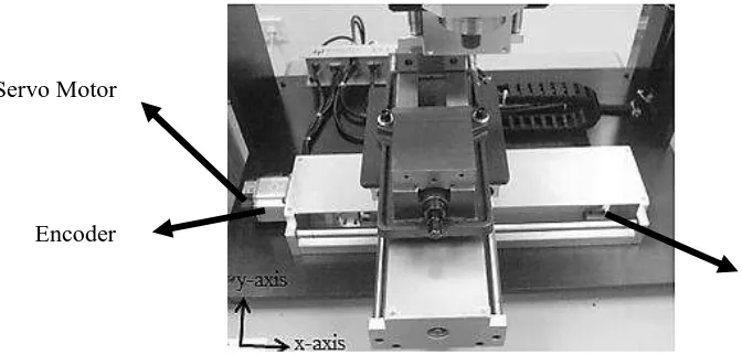
Figure 1 shows the ball-screw driven XY milling table of an XYZ-Stage produced by Googol Tech. The XY milling table consists of two axes namely; x and y axes, driven by two Panasonic MSMD 022G1U A.C. servo motors respectively. Both axes are equipped with an incremental encoder for positioning measurement. The resolution of the encoder is 2500 pulse/rev with screw pitch of 5 mm and multiple frequencies of 4. In other words, the resolution of the encoder is 0.0005 mm/pulse. Two limit switches are located in the near end of both axes. The total mass of x-axis is 36.8 kg while the total mass of the y-axis is 23.4 kg. The XY milling table consists of two axes namely; x and y axes, driven by two Panasonic MSMD 022G1U A.C. servo motors respectively. Both axes are equipped with an incremental encoder for positioning measurement. The resolution of the encoder is 2500 pulse/ rev with screw pitch of 5 mm and multiple frequencies of 4. In other words, the resolution of the encoder is 0.0005 mm/pulse. Two limit switches are located in the near end of both axes. The total mass of x-axis is 36.8 kg while the total mass of the y-axis is 23.4 kg.
Figure 1.Googoltech xy milling table ballscrew drive system
Limit Switch Servo Motor
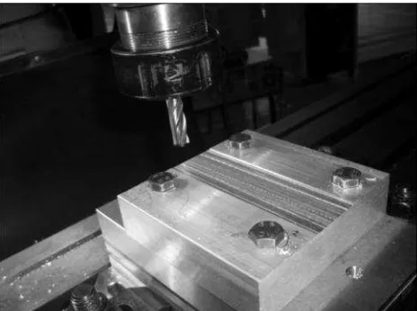
Figure 2 shows the milling process during the collection of disturbance cutting force data. The aluminium block is placed on top of the Kistler Dynamometer. The diameter of the milling cutter is 10mm. The depth of cut is 0.5mm with the feed rate of 502 mm/min.
Figure 2.Milling operation performed for the purpose of collection of cutting force data
Figure 3shows a schematic diagram of the overall system. The XY milling table is linked to a servo amplifier which is then connected to a DS1104 DSP board. A personal computer, equipped with ControlDesk and MATLAB software is linked to the DSP board to apply control design and data collection.
Figure 3.Schematic diagram of the overall system
3. Controller design
Three types of controller namely; Cascade Proportional/Proportional Integral (P/PI) controller, Nonlinear PID (NPID) controller and Nonlinear Cascade (N-cascade) controller is chosen to control the position of the system. The system identification process has been carried out in [10-12]. In general, the plant is an XY table system driven by ballscrew drive. The transfer function of the plant is as follows:
3 . 166 8
. 144
69380
2
S S
U Y
(1)
where Y is the position of the table in millimeter and U is the input voltage signal in volt.
3.1. Design of controller 1(Cascade P/PI)
Cascade P/PI controller belongs to the conventional group of controller and this control structure is widely applied in most machine control algorithm. The cascade P/PI control consists of a PI controlled inner velocity loop with a P controller in the outer position loop. Figure 4 shows the basic structure of a cascade P/PI controller [13].
Figure 4.Basic structure of a cascade P/PI controller
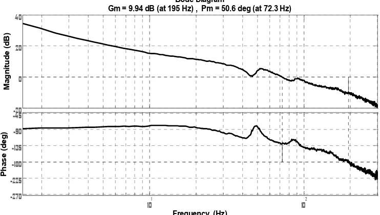
The velocityPI controller is first designed before the P (position) controller. Figure 9 and 10 show the Bode open loop transfer function of the speed loop and the Nyquist plot of the position open loop respectively. Figure 11 shows the Bode diagram of the position loop sensitivity transfer function that indicates a system bandwidth of about 41.2 Hz. To conclude, Table 2 illustrates the finalized values of Kp, Kiand Kvfor the controlled system.
-20
-1 -0.9 -0.8 -0.7 -0.6 -0.5 -0.4 -0.3 -0.2 -0.1 0
Figure 6.Nyquist plot of open loop position transfer function via cascade P/PI
101 102 103
Figure 7.Bode plot of position sensitivity transfer function via cascade P/PI
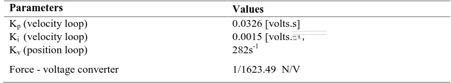
Table 2: List of the control parameters of the cascade P/PI controller
Parameters Values
Kp(velocity loop) 0.0326 [volts.s]
Ki (velocity loop) 0.0015 [volts. 2]
Kv(position loop) 282s-1
Force - voltage converter 1/1623.49 N/V
3.2. Design of controller 2[Nonlinear PID(NPID) controller]
In general the suggested nonlinear PID (NPID) controller is developed by a sector bounded nonlinear gain, K(e) that is integrated in series (cascade) with PID controller. Figure 8 illustrates the block diagram of the NPID control system. The parameters of the traditional PID controller are acquired based on previous work [14] which is based on the desired gain and phase margin. The self tuned gain adjustment, K(e) behave as a nonlinear function of error, e(t) which is bounded in the sector 0 K(e) K(emax) as pointed out in equation 2 and equation 3. These can be classified as the range of
available choice for the nonlinear gain, K(e). The output formed from this nonlinear function is acknowledged as scaled error, fe and the equation of fe is presented in equation 4. Alternatively, the
overall equation of NPID controller can be viewed as in equation 5.
Figure 8.Block diagram of the NPID control system [15]
Nonlinear Gain , (2)
e ; if |e|≤ emax
Error, e = emax*sign(e); else |e| > emax (3)
Scaled Error, fe= K(e)*e(t) (4)
General transfer function of NPID, GNPID(s) = [Kp*fe]+[Ki/S*fe]+[KdS*fe] (5)
Table 3. List of the control parameters of NPID controller
Parameters Values
Range of error, Emax 3.0 [mm]
Range of variation of Nonlinear Gain, 0.5
Proportional Gain, Kp 1.32 [volts/mm]
Integral Gain, Ki 0.000825 [volts/mm.s]
3.3. Design of controller 3[Nonlinear cascade (N-Cascade) controller]
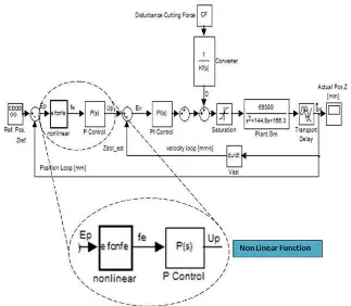
Basically, the proposed nonlinear cascade controller is constructed by a combination of two basic function block; namely nonlinear function and cascade P/PI function block. By combining those two function blocks, it is expected that this controller could inherit the plus point of Nonlinear function in NPID controller and the robustness characteristic from cascade P/PI controller. In other words, by having the characteristics of nonlinear function and robustness properties, the controller could have the ability not only to compensate cutting force disturbance at fix value but also at multiple value. It is because the nonlinear algorithm has automatic self-adjusting mechanism in which it will inject higher gain when the system detect higher value of error and in contrast, it will inject lower gain when the system detect lower value of error. Figure 9 portrays the block diagram of nonlinear cascade control structure.
Figure 9.Block diagram of the nonlinear cascade control system
Table 4. List of the control parameters of Nonlinear Cascade controller
Parameters Values
Range of error, Emax 0.1465 [mm]
Range of variation of Nonlinear Gain, 2.0
Proportional Gain, Kv (Position Loop) 450 [s-1] Proportional Gain, Kp (Velocity Loop) 0.007594 [volts.s]
Integral Gain, Ki (Velocity Loop) 1.0 [volts. 2]
4. Result and discussion
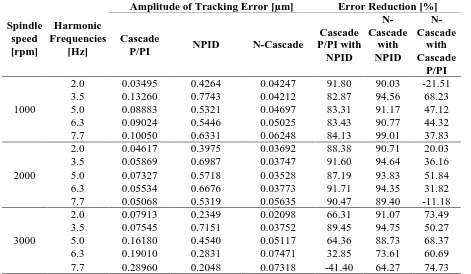
The measured cutting forces are injected to the system (as illustrated in figure 4) as disturbances. The tracking performance cascade P/PI, Nonlinear PID (NPID) and Nonlinear Cascade (N-cascade) controller are analysed and compared based on their robustness against variable cutting force disturbance. Analyses on magnitudes of the harmonic components of the error signal is conducted in order to quantify the compensation performance of these controllers against external cutting forces. Table 5 compares the harmonic amplitudes of the position error signal recorded between cascade P/PI, Nonlinear PID (NPID) and Nonlinear Cascade (N-cascade) at varying spindle speed rotations. As expected, the N-cascade controller produces improved performance compared to the other two controllers. The results appeared to concur as N-cascade controller successfully inherit the attributes of NPID controller and cascade P/PI controller.
Table 5. FFT Analyses on harmonic components of the position errors
Spindle
Amplitude of Tracking Error [µm] Error Reduction [%]
Cascade
2.0 0.03495 0.4264 0.04247 91.80 90.03 -21.51
3.5 0.13260 0.7743 0.04212 82.87 94.56 68.23
5.0 0.08883 0.5321 0.04697 83.31 91.17 47.12
6.3 0.09024 0.5446 0.05025 83.43 90.77 44.32
7.7 0.10050 0.6331 0.06248 84.13 99.01 37.83
2000
2.0 0.04617 0.3975 0.03692 88.38 90.71 20.03
3.5 0.05869 0.6987 0.03747 91.60 94.64 36.16
5.0 0.07327 0.5718 0.03528 87.19 93.83 51.84
6.3 0.05534 0.6676 0.03773 91.71 94.35 31.82
7.7 0.05068 0.5319 0.05635 90.47 89.40 -11.18
3000
2.0 0.07913 0.2349 0.02098 66.31 91.07 73.49
3.5 0.07545 0.7151 0.03752 89.45 94.75 50.27
5.0 0.16180 0.4540 0.05117 64.36 88.73 68.37
6.3 0.19010 0.2831 0.07471 32.85 73.61 60.69
7.7 0.28960 0.2048 0.07318 -41.40 64.27 74.73
called water bed effect. It means when at certain point the error is being push to reduce, the other point will be likely to increase. Results also show that nonlinear cascade controller is able to compensate and reduce tracking error components generated from various different cutting force disturbances.
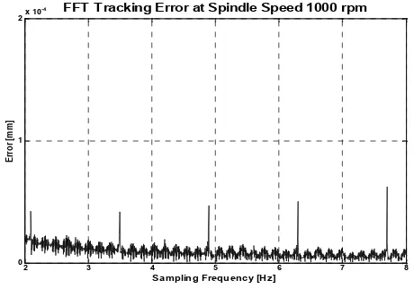
Figure. 10. FFT Error via NPID Figure 11. FFT Error via Cascade P/PI
2 3 4 5 6 7 8
FFT Tracking Error at Spindle Speed 1000 rpm
Figure 12. FFT Error via Nonlinear cascade
5.
ConclusionIt can be concluded that the performance of Nonlinear Cascade controller outweigh both NPID and cascade P/PI controller. The maximum FFT tracking errors of Nonlinear Cascade is approximately about 0.07471 micrometer, while for the case of NPID and cascade P/PI controllers, the maximum FFT tracking errors are 0.7743 and 0.28960 micrometer respectively. Analyses on the harmonics content of the position tracking errors have shown the supremacy of Nonlinear cascade (N-cascade) controller. The advantages of the implementation of N-cascade in machine tools applications are obvious in which it will increase the quality of the end product and the productivity in industry by saving the machining time.
NPID FFT Tracking Error at 1000rpm Spindle Speed
2 3 4 5 6 7 8
FFT Tracking Error at1000 rpm Spindle Speed
Acknowledgement
This research is financially supported by the Short Term Grant Scheme (PJP), Centre for Research and Innovation Management with reference no. PJP/2012/FKP(57A)/S01064 and the Faculty of Manufacturing Engineering, Universiti Teknikal Malaysia Melaka (UTeM).
6. References
[1] Kalpakjian, S., and S. Schmid, 2006. Manufacturing Processes for Engineering, (3rd ed.). Addison Wesley : Longman.
[2] Jamaludin, Z., H.V. Brussel, G. Pipeleers and J. Swevers, 2008. Accurate motion control of XY high-speed linear drives using friction model feedforward and cutting forces estimation. CIRP Annals–Manufacturing Technology, 57(1) : 403-406.
[3] Pritschow, G. and W. Phillip, 1992. Research on the efficiency of feedforward controllers on machine direct drives. CIRP Annals–Manufacturing Technology, 41(1) : 411-415.
[4] Skogestad, S., and I. Posletthwaite, 2005. Multivariable Feedback Control - Analysis and Design, Chichester, West Sessex, England, John Wiley & Sons.
[5] Wang, J., 2004. Robust tracking controller design with application to the motion control of an x-y feed table for high-speed machining”, PhD Thesis, Faculty of Engineering, Department of Mechanical, Division of Production, Machine Design and Automation (P.M.A), Katholieke Universiteit Leuven, Belgium.
[6] Jamaludin, Z., H.V. Brussel and J. Swevers, 2008. Quadrant glitch compensation using friction model-based feedforward and an inverse-model-based disturbance observer, Proc.Int. Conf.on Advanced Motion Control, Centro Santa Chiarra Hotel, Trento, Italy. 26 - 28 March 2008.
[7] Jamaludin, Z., H.V. Brussel and J. Swevers, 2007. Classical cascade and sliding mode control tracking performances for a x-y feed table of a high-speed machine tools, Int. J. of Precision Technology, 1(1) : 65-74.
[8] Hara, S., Y. Yamamoto, T. Omata and M. Nakano, 1988. Repetitive control system: a new type servo system for periodic exogenous signals, IEEE Trans. on Automatic Control, 33(7) : 659-668. [9] Pipeleers,G., B. Demeulenaere, J. DeSchutter, and J. Swevers , 2008. Robust High-Order
Repetitive Control: Optimal Performance Trade-Offs, Automatica, 44(9) : 2628-2634.
[10] Abdullah, L., Z. Jamaludin, T.H. Chiew, N.A. Rafan and M.S. Syed Mohamed, 2012. System identification of xy table ballscrew drive using parametric and non parametric frequency domain estimation via deterministic approach . Procedia Engineering, 41(1) : 567-574.
[11] Pintelon, R. and J. Schoukens, 2001. System identification–A frequency domain approach, New York: IEEE Press.
[12] Pintelon,R., P. Guillaume, Y. Rolain, J. Schoukens, and H. Van Hamme, 1994. Parametric Identification of Transfer Functions in the Frequency Domain – A Survey. IEEE Trans.on Automatic Control, 39(11) : 2245-2260.
[13] Abdullah, L., Z. Jamaludin, Q. Ahsan, J. Jamaludin, N.A. Rafan, T.H. Chiew, K. Jusoff and M. Yusoff, "Evaluation on tracking performance of PID, Gain Scheduling and Classical Cascade P/PI controller on XY Table Ballscrew Drive System". World Appl. Sci. J., Vol. 21, pp. 01-10, 2013
[14] Seraji, H., “ A new class of nonlinear PID controllers with robotic applications”. Journal of Robotic System, Vol. 15, No. 3, pp. 161-181, 1998
![Figure 8. Block diagram of the NPID control system [15]](https://thumb-ap.123doks.com/thumbv2/123dok/531465.61495/7.595.140.462.269.412/figure-block-diagram-npid-control.webp)