Research Article
Improvement of Energy Density in Single Stator Interior
Permanent Magnet Using Double Stator Topology
Raja Nor Firdaus,
1,2Norhisam Misron,
1,3Chockalingam Aravind Vaithilingam,
4Masami Nirei,
5and Hiroyuki Wakiwaka
61Department of Electrical and Electronics, Faculty of Engineering, Universiti Putra Malaysia, Malaysia 2Faculty of Electrical Engineering, Universiti Teknikal Malaysia, Melaka, Malaysia
3Institute of Advanced Technology (ITMA), Universiti Putra Malaysia, 43400 Serdang, Selangor, Malaysia 4CIARG, School of Engineering, Taylor’s University, 47500 Selangor, Malaysia
5Nagano National College of Technology, 716 Tokuma, Nagano 381-8550, Japan 6Shinshu University, 500 Wakasato, Nagano 380-8553, Japan
Correspondence should be addressed to Norhisam Misron; [email protected]
Received 18 October 2013; Revised 15 March 2014; Accepted 21 March 2014; Published 23 April 2014 Academic Editor: Sergio Preidikman
Copyright © 2014 Raja Nor Firdaus et al. his is an open access article distributed under the Creative Commons Attribution License, which permits unrestricted use, distribution, and reproduction in any medium, provided the original work is properly cited.
he paper presents the energy density improvement using magnetic circuit analysis of the interior permanent magnet motor. he leakage lux from the conventional structure is improved with modiied magnetic circuit to improve the energy and thereby the torque value. his is approached with a double stator structure design. he proposed structure is investigated with two design variations, namely, the double stator with thin pole shoe and the double stator with thick pole shoe motors. Variations in the mechanical parameters of the all the developed models are analyzed through the inite element analysis tool. In all investigations the magnetic source is ixed in both the permanent magnet volume and coil magnetomotive force, respectively, as 400 mm3per each pole and 480 Ampere turns per pole. From the analysis the best it magnetic structure based on the torque characteristics is derived and is fabricated for the same volume as that of the conventional structure for performance evaluations. It is found out that there is improvement on the motor constant square density for the proposed improved magnetic circuit through the best it double stator with thick pole shoe by about 83.66% greater than that of the conventional structure.
1. Introduction
Single phase interior permanent magnet (IPM) motors are adopted in many low cost applications such as in fan, blowers, and other domestic appliances [1–5]. he main disadvantage of using single phase compared to three-phase permanent magnet motor is its inability to self-start [6–8]. However, for speciic application such as the mechanical chopper, the single phase motor is the most popular application due to the safety consideration. he requirement for such type of motor is of high torque with low cogging torque values. A high torque performance motor usually comes with high cogging characteristic that introduces torque ripple inside the motor. A pure sinusoidal torque characteristic ensures uniform lux distribution that produce smooth speed rotation
with negligible torque ripple [9–12]. he cogging torque is caused by the variation of the magnetic energy of the ield due to the interaction of permanent magnet (PM) and the slot under the mechanical angular position of the rotor [13–15]. here are many possible ways to reduce cogging torque such as skewing, optimizing, or varying the magnet pole arc width and introduction of dummy slots [16,17]. However, each of them gives signiicant variations in the output torque value. he increase in magnetic energy signiicantly increases the torque value that is realized by resizing the volume of the magnet or with introduction of larger number of coil turn [18–20]. However, the lux density in some parts of stator or rotor of permanent magnet motor is increased leading to saturation value as the volume of magnet is increased. At this saturation point, the magnetic energy no longer contributes
to torque generation and is considered as air gap that is highly inefective. herefore, study on ways to optimize the magnetic energy low perpendicular to the air gap surface inside a permanent magnet motor is to be investigated at the irst stage. An optimal air gap magnetic energy with reduction of cogging torque value is realized through a sinusoidal torque waveform. hen, the process of resizing the PM volume or adding the number of coil turn is used to estimate the performance limit of the desired motor.
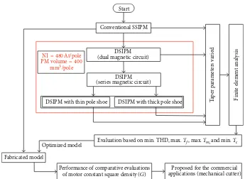
his paper presents the analysis on the magnetic circuit design of single stator and double stator and the improvement in the magnetic energy of the double stator with magnetic circuit design. Analysis on the variations of the mechanical parameter that changes the optimal magnetic energy in the air gap that contributes to the generation of torque char-acteristics of the all structures is presented. Finite element analysis (FEA) is used as a numerical tool to derive the torque characteristics based on various combinations of taper parameters. he analysis result shows that minimum value of total harmonic distortion (THD) is found by optimizing the dimensions of the width of slot and that of the rotor. Also it is found that with reducing height of stator teeth a symmetrical torque waveform is evolved. he analysis is evaluated based on the value of the minimum total harmonic distortion (THD), the maximum fundamental torque ��, the maximum peak torque��, and the minimum cogging torque��. For comparative evaluations, the motor constant square density (G) is used. he model of improved series magnetic circuit is fabricated and tested experimentally. he comparison result shows that measurement results have good agreement with the simulation result.
2. Machine Design and Magnetic Circuit
Design Analysis
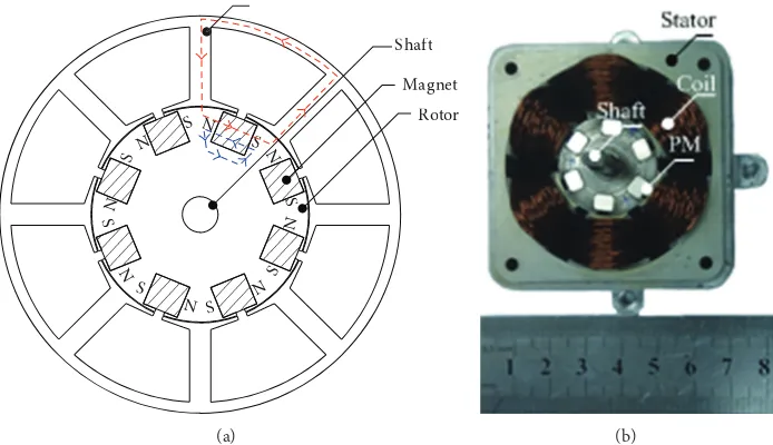
2.1. Single Stator Structure. Figure 1 shows the typical
sin-gle stator interior permanent magnet (SSIPM) [16–20]. In this research, the 6-pole 6-slot coniguration of permanent magnet motor is considered. his is due to the speciic application that requires both torque and speed for portable mechanical chopper used in agricultural sector. he overall diameter of the permanent magnet motor is set for 55 mm with 5 mm diameter of shat. he permanent magnet is made from NdFeB grade of 42 with a dimension of 4 mm of width and 5 mm of height. he technical property of the permanent magnet is shown in Table 1. he shat is made from nonmagnetic steel (SUS304). he rotor and stator are made up of standard silicon steel known as JI: 50H800. he stack length and the air gap length between stator and rotor are set for 20 mm and 0.1 mm, respectively.
It comprises of a stationary stator and the rotational rotor that moves to develop the torque. With variety in design structure available in the literature, the above structure shows the conventional design with an outside stationary rotor and an inside cylindrical rotor coupled to the output shat. he stator comprises of set of energised copper coils in succession to generate the magnetic lux. he stator lux interacts with the rotor, which is mounted inside the rotor in such a way
Table 1: Parameters varied in this investigation.
Property Values
Remanent lux density,��[T] 1.28–1.32
Coercivity,��[kA/m] >923
Intrinsic coercivity,���[kA/m] >955
BH max, kJ/m3 318–342
Operating temperature,� 20∘C to 120∘C
that it can turn to align itself with the ields generated by the coils. his full alignment force generates torque, turning the rotor so that it moves the load through the shat.
2.2. Magnetic Circuit Analysis of Single Stator Structure.
Figure 2 shows single stator interior permanent magnet
(SSIPM) motor type that forms two parallel magnetic circuits: one magnetic circuit is enclosed by stator and coils while the other magnetic circuit is in the rotor side. However, only magnetic circuit in the stator side is involved in the torque generation process as it consists of air gap where by the force is developed in this region. In this magnetic circuit, it has much reluctance as the lux is surpassing from the permanent magnet to the stator and coming back to its origin point. he reluctances in other magnetic circuit which are
2�rp1,2�rp2, and�rp3unused as the magnetic energy of the
permanent magnet is been divided (reluctance torque) and not being used for torque production. he net reluctance in the magnetic circuit is given as
� = [�osy+ 2 (�sps+ �sp) + 2 (�rp) + 2�ag] . (1)
he reluctance torque��in the rotor circuit that is unused is given as follows:
��= [2�rp1+ 2�rp2+ �rp3] (2)
is unused as there is no useful energy produced in the circuit. In other words, if the unused leakage lux in the air gap is efectively utilized through another magnetic circuit, then the torque density can be improved.
2.3. Magnetic Circuit Design Concept. he motivation on the
introduction of magnetic circuit in the rotor part of the single stator interior permanent magnet (SSIPM) structure is proposed in this section. he design improvements in the magnetic circuit are highly inluenced by the property of the material that is involved in the energy conversion process and also the efective area of energy conversion. From the irst principles of magnetism, the reluctance in a magnetic circuit is given as
� = ����
�, (3)
N
Figure 1: Conventional SSIPM. (a) Structural conigurations; (b) fabricated SSIPM motor.
Flux
Magnetic torqueTm Reluctance torqueTr
(a)
Rrp: the reluctance of rotor pole Rag: the reluctance of air gap Rsps: the reluctance of stator pole shoe Rsy: the reluctance of stator yoke Rrp1: the reluctance of rotor area1 Rrp2: the reluctance of rotor area2 Rrp3: the reluctance of rotor area3
N
Figure 2: Magnetic circuit analysis of the SSIPM. (a) Magnetic lux low path; (b) equivalent magnetic circuit low.
contact area between the parts of the magnetic circuit would heavily inluence the net magnetic circuit values and thereby the torque density value of the machine. In a magnetic circuit with the air gap��> 0, most of the MMF is expended on the air gap and most of the energy is stored in the air gap with its volume����, where��is the cross section area of the air gap. he energy per volume is given as
� = �� instantaneous electric current. herefore the energy in the reluctance torque produced surface is given as
� = �0(��)2
�� ��. (5)
N
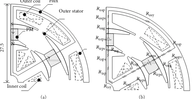
Rosps: the reluctance of outer stator pole shoe Risps: the reluctance of inner stator pole shoe Roag: the reluctance of outer rotor air gap Riag: the reluctance of inner rotor air gap Risy: the reluctance of inner stator yoke Rosy: the reluctance of outer stator yoke Risp: the reluctance of inner stator pole Rosp: the reluctance of outer stator pole Rirp: the reluctance of inner rotor Rorp: the reluctance of outer rotor
(b)
Figure 3: Magnetic circuit analysis of the DSIPM. (a) Magnetic lux low path; (b) equivalent magnetic circuit low.
2.4. Double Stator Interior Permanent Magnet (DSIPM)
Machine. he rotor leakage lux from the SSIPM is catered
with the introduction of another stator structure inside the machine, known as double stator interior permanent magnet (DSIPM) motor. It has two stators known as an outer and inner stator. heoretically, this two magnetic circuits arrangement provides higher torque production compared to single stator since two air gaps are provided in between stator and rotor. Based on the magnetic equivalent circuit of this model, the lux has to go through 2�osp, 2�osps, 2�orp, and�osy
for outer stator side magnetic circuit. In the inner stator side magnetic circuit the lux has to go through 2�isp, 2�isps, 2�irp,
and�isy. his contributes higher reluctance which afects the
lux through any cross section of a magnetic circuit. he feature that includes the additional stator is introduced in the rotor side known as double stator, with parallel magnetic circuit topology (Figure 3). he resultant magnetic circuit of the DSIPM (only for one sector of energy conversion) of magnetic circuit is as given by
� = [�osy+ 2 (�sps+ �sp ) + 2 (�orp) + 2�ag]
‖ [�isy+ 2 (�sps+ �sp ) + 2 (�orp) + 2�ag] .
(6)
2.5. Magnetic Circuit Improvements. However, there is a large
area of ferromagnetic material on the rotor part that afects the lux through any cross section of rotor magnetic circuit. he value of�orpand�agis critical in developing the torque
density as it is the point at which the efective magnetic energy and the electromagnetic energy interacts to develop the torque. By the variations of the mechanical parameter at
this point contact the energy density is improved. he efect of the converging area at the point of contact (between the magnet and the stator) is improved with the use of pole shoe. Further to the conversion of the DSIPM of parallel magnetic circuit to series magnetic circuit by changing the orientation of the magnet. he introduction of the pole shoe divides the lux path in the magnetic circuit introducing reluctance components. he variations of the reluctance components are investigated through the variations in their height and width. Further the size ratio of the magnet inluences the torque density due to the orientation of the magnetic grains inside the machine.
his variation in the magnet in this investigation is classiied to be of the DSIPM with thin pole shoe and DSIPM with thick pole shoe. he resultant magnetic circuit reluctance value is as shown in
� = [�osy+ 4 (�sps+ �sp ) + 2 (�orp) + 4�ag]
+ [�isy+ 2 (�irp)] .
(7)
N
Figure 4: Magnetic circuit analysis of the DSIPM with thin pole shoe. (a) Magnetic lux low path; (b) equivalent magnetic circuit low.
ration of width to height values but keeping the net volume of magnet ixed 400 mm3 volume, the DSIPM with thick pole shoe is evolved. his increases the efective area between permanent magnet and pole shoe. As can be seen in both pole shoe structures the magnetic circuit is serial in nature and hence the torque density is expected to improvise compared to the parallel circuit of the double stator IPM structure.
2.5.1. Double Stator hin Pole Shoe Conigurations (DSIPM
with hin Pole Shoe). he features of the double stator
thin pole shoe conigurations with series magnetic circuit topology include the inluence on the magnetic energy in the air gap that is afected by the permanent magnet area. he magnetic energy in the air gap can be improvised by having thinner pole shoe to reduce the reluctance torque value (Figure 4).
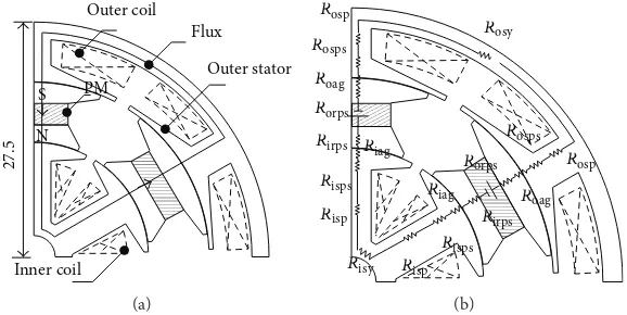
2.5.2. Double Stator hick Pole Shoe Conigurations (DSIPM
with hick Pole Shoe). In this coniguration with the series
magnetic circuit, the permanent magnet width and height values are interchanged with ixed magnet volume to increase the efective area between permanent magnet and pole shoe. he magnetic energy improvement in the airgap can be achieved with the introduction of thinner magnet and increasing the pole shoe contact area (Figure 5).
he additional air gap reluctance between the stator and rotor inluence the improvement in the torque density values. However the design has to be optimized in order to minimize the efect of radial pull. Also the construction of this type of structures using the double stator topology is quite challenging. he analysis of the proposed magnetic circuit by the variations in the various mechanical parameters is essential to have a comprehensive analysis of the results. he parameters used in this investigations include the width of outer stator (�os∘), width of inner stator (�is∘), width of
outer rotor (�or∘), width of inner rotor (�ir∘), height of outer
stator pole teeth (�ospt), height of inner stator pole teeth
(�ispt), and height of rotor teeth (�rth). For simpliication,
a ratio is known as ratio of slot and pole width (��∘ ��∘) that shows the efect of air gap area between the stator and
rotor width is used in the investigations. All of the proposed magnetic circuit is constructed using standard inite element tool as described in the next section in brief.
3. Numerical Analysis
3.1. Finite Element Method. In order to facilitate the torque
characteristics of single phase DC permanent magnet motor based on the magnetic circuit design inite element analysis (FEA) is employed to predict the magnetic distribution. Finite element analysis (FEA) is used to compute the mag-netic characteristics, but this necessitates a package and more time for modeling the motor and is used extensively by researchers in machine design. Most of them use compu-tational tools to demonstrate the irst hand information on the property of the machine [18–20]. he FEA tool used in this investigation is developed based on the nodal force method [24]. his method is similar to the method of inding equivalent nodal force from distributed load force in stress analysis. he magnetic volume and the surface forces are through the Maxwell stress tensor using the Einstein’s summation convention. For any three-dimensional volume of boundary surface,���is the stress tensor and�is the unit vector from region 1 to region 2 perpendicular to the surface; then the Maxwell stress tensor is given by
���= ����− ������, (8) where � is the Kronecker’s delta (here ��� is a piecewise function of variables�and�with the value being 1 when� = �; else it is zero) and the coenergy density is given in
���= ∫ �
0 � ��. (9)
In FEM calculations that use the Maxwell method alone, the discontinuity occurs due to the interpolation functions at the element interfaces.
he nodal force���is then given as
N
Figure 5: Magnetic circuit analysis of the DSIPM with thick pole shoe. (a) Magnetic lux low path; (b) equivalent magnetic circuit low.
In the above equation the integration is over the elements that connect the nodes in the design. he virtual displacement for the work done by the magnetic force is given as
�� = ∑
� (− ∫ ��������∇) ���, (11) where��is the nodal shape function and ���is the virtual nodal displacement. With no spatial diferentiation of the ield quantities of �,�is needed and the discontinuity of the calculated ield causes no diiculties; the resultant force is calculated by summation of the nodal forces at various nodes in the body. he formulation does not depend on the interpolation functions as used in other FEA tools. Hence the results originated from this FEA tool are highly accurate even though the computation calculation is heavier.
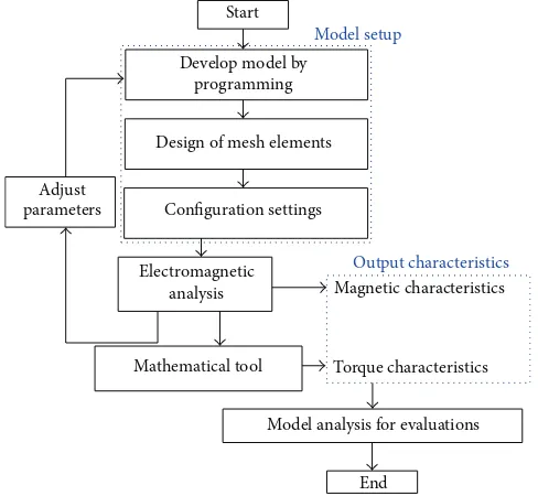
3.2. Design Formulations. Figure 6(a) shows the meshing
constructed for the analysis of the IPM structure. In order to make the FEM calculations more accurate there are six cir-cular tubes that are constructed in the programming design in both the two air gap surfaces as inFigure 6(b). he design sequence in the programming of the FEA in this investigation is as inFigure 7. It involves three stages; the irst one is the development of model based on the design parameters and the setting of the mesh points and the coniguration settings including the number of turns and the impressed current. he second stage is the computations of the designed model. he third stage is to derive the magnetic and mechanical values from the computations results. Both extraction and analysis for the machine performance are used by mathematical tool sotware. he automatic variations on the parameter can be set in the analysis and hence the computation is relatively eas-ier once the basic mechanical structure is constructed using the FEA programming tool. he model used mesh generators that construct using Delaunay triangulation method. his self-adapting mesh relies on an accurate and reliable method of estimating the discretization error in the mesh. he mesh accuracy can be controlled by the user accordingly in the inite element calculation. he air gap of model has been divided up to six layers of meshes and the modeling of each geometry developed according to the parameter changes.
his has reduced the calculation time and provides accurate simulation result.
3.3. Design Evaluations. he torque characteristic of interior
permanent magnet motor is compared through values of maximum torque (��), cogging torque (��), fundamental torque (��), and total harmonic distortion (THD).��can be described as the peak of torque waveform. In this research,
��is the actual torque that is calculated from FEA. he��is not a direct indication of the torque characteristics to exhibit a high component value of torque.��is the torque generated due to the interaction between the permanent magnet of the rotor and the stator.��is an undesirable component for the operation of a motor. In this research,�is an actual torque that is calculated from FEA.
��can be described as the fundamental harmonic of the torque waveform calculated by fast Fourier transform (FFT) analysis. he fundamental torque presents the component of sinusoidal torque waveform in the torque characteristics. his means that higher value of fundamental torque develop higher torque component in the torque waveform. Based on the simulation result of torque for every combination taper parameter of each magnetic circuit, lists of torque charac-teristics are developed. From the torque characteristic itself, four components known as the total harmonic distortion (THD), fundamental torque ��, the maximum torque ��, and cogging torque �� are determined. From this overall data, selection is made based on minimum total harmonic distortion (min. THD), maximum fundamental torque (max.
(a)
6th layer 1st layer
(b)
Figure 6: Mesh setting inside the FEA. (a) Mesh of the design; (b) six layers of mesh in the air gap set for FEA.
Start
Model setup
Develop model by programming
Design of mesh elements
Adjust
parameters Configuration settings
Electromagnetic analysis
Output characteristics
Magnetic characteristics
Torque characteristics
Model analysis for evaluations
End Mathematical tool
Figure 7: Magnetic circuit analysis using FEA.
3.4. Analysis Parameters. Table 2shows the various
parame-ters used in the analysis. As instance for the case of the SSIPM type motor can be seen for each of the ratio the stator to rotor width (��∘ ��∘) the taper height (�spt) is varied. In
this design the maximum swept angle for the analysis is60∘ and with a clearance of6∘the possible ratio of (��∘ ��∘) is analysed for other parameters as shown inTable 3.
he double stator topology involves two taper parameters, namely, outer stator taper (�ospt) and inner stator taper
(�ospt). Hence for the same ratio values of stator to rotor width
value the tapers are varied and the values are plotted. Based on the overall analysis data of taper parameter, an evaluation is proposed to select the best possible it from the various possible combination values. he method is to plot all data in single graph based on the ratio of slot and pole width as
the taper height is varied.Table 3shows the taper parameters used in the single stator and double stator topology.
4. Results and Discussions
4.1. Numerical Result Analysis. For each of the combinations
fromTable 3the values of��,��,��, and THD for the single
NI= 480At/pole
DSIPM with thin pole shoe DSIPM with thick pole shoe Tap
er pa
Performance of comparative evaluations of motor constant square density (G)
Proposed for the commercial applications (mechanical cutter)
Figure 8: Methodology in the magnetic circuit evaluation strategy.
Table 2: Parameters varied in this investigation.
SSIPM DSIPM DSIPM with thin pole shoe DSIPM with thick pole shoe
Hspt
Table 3: Values of taper parameters used in the simulation.
Single stator topology (SSIPM) Double stator topology (DSIPM)
Parameter Range of values Parameter Range of values
��∘ 54∘, 52∘, 50∘, 48∘, 46∘ �os∘ 46∘, 48∘, 50∘, 52∘, 54∘
magnetic circuit structure.Table 5shows the values of��,
��, ��, and THD for each evaluation type. With respect to the choice on the minimum THD evaluation type of SSIPM the values of ��, ��, ��, and THD are 0.97 Nm, 0.008 Nm, 0.566 Nm, and 57.88%, respectively. For double
Table 4: Selection of min. THD, max.��, max.��, and min.��based on evaluation type.
Ratio of stator and rotor width 3.0
Ratio of stator and rotor width 0.8 0.9 1.0 1.1 1.2
Ratio of stator and rotor width 3.0
Ratio of stator and rotor width 0.8 0.9 1.0 1.1 1.2
Ratio of stator and rotor width 3.0
Ratio of stator and rotor width 0.8 0.9 1.0 1.1 1.2
Ratio of stator and rotor width 3.0
Ratio of stator and rotor width 0.8 0.9 1.0 1.1 1.2
Ratio of stator and rotor width 3.0
Ratio of stator and rotor width 0.8 0.9 1.0 1.1 1.2
Ratio of stator and rotor width 3.0
Ratio of stator and rotor width 0.8 0.9 1.0 1.1 1.2
Ratio of stator and rotor width 3.0
Ratio of stator and rotor width 0.8 0.9 1.0 1.1 1.2
Ratio of stator and rotor width 3.0
M
at
h
ema
tica
lP
ro
b
lem
s
in
En
gi
neer
in
g
Table 5: Values of��,��,��, and THD based on evaluation types.
Evaluation type � SSIPM DSIPM DSIPM with thin pole shoe DSIPM with thick pole shoe
�[Nm] ��[Nm] ��[Nm] THD % ��[Nm] ��[Nm] ��[Nm] THD % ��[Nm] ��[Nm] ��[Nm] THD % ��[Nm] ��[Nm] ��[Nm] THD %
Min THD 0.97 0.008 0.566 57.88 1.308 0.0120 0.648 91.77 1.045 0.041 0.852 30.71 2.01 0.2325 1.60 42.56
Max�� 1.13 0.016 0.699 70.09 1.306 0.0195 0.809 101.12 1.583 0.072 1.169 39.99 2.08 0.2303 1.65 43.37
Max�� 1.58 0.016 0.671 92.74 2.322 0.0335 0.661 148.14 2.352 0.064 1.1563 67.54 2.94 0.3512 1.58 61.19
M
SSIPM DSIPM with thin pole shoe
DSIPM DSIPM with thick pole shoe
F
SSIPM DSIPM with thin pole shoe
DSIPM DSIPM with thick pole shoe
(d)
Figure 9: Choice on the best it value of��,��,��, and THD. (a) Maximum torque; (b) minimum cogging torque; (c) fundamental torque; (d) total harmonic distortion.
0.041 Nm, 0.852 Nm, and 30.71%, respectively. Selections of min. THD evaluation type of DS thick pole shoe for values of
��,��,��, and THD are 2.0172 Nm, 0.11769 Nm, 1.6045 Nm, and 42.56%, respectively. For value of��, the DS thick pole shoe produced the highest��of 3.0 Nm with higher cogging torque 0.38 Nm, respectively. he average of �� in DSIPM is approximately 0.7 Nm and increases up to an average of 1.0 Nm in DS thin pole shoe while 1.5 Nm in DSIPM with thick pole shoe. his shows that DSIPM with thick pole shoe produces better result of torque component. It can be seen that the range of THD value is from 91% compared to that of the DSIPM, whereas for DS thin pole shoe it is from 30% to 90%. For DSIPM with thick pole shoe, the range of THD value is from 40% to 90%. he optimal value is selected (as shown by red line) to indicate the improvement of each model. he fabricated SSIPM is with the best it that exhibits performance with the choice of minimum THD.
Figure 9shows the optimum value of��,��,��, and THD
as indicated by red lines ofTable 5. It can be seen that the optimal of max.��is increased for each proposed magnetic circuit topology.Figure 9(a)shows that the maximum torque is achieved with the magnetic circuit improvements, with reduced cogging torque as seen inFigure 9(b). But for the DSIPM and DSIPM with thin pole shoe the cogging torque
is reduced but the harmonic content is increased that would eventually reduce the average torque. he DSIPM with thick pole shoe exhibits reduced harmonic content deriving higher average torque along with the maximum torque. Each of the proposed magnetic circuit developed produces signiicant increment in terms of��,��, ��, and decrement of THD but the choice on the torque density makes the DS thick pole shoe a better choice due to its better fundamental torque with reduced THD.
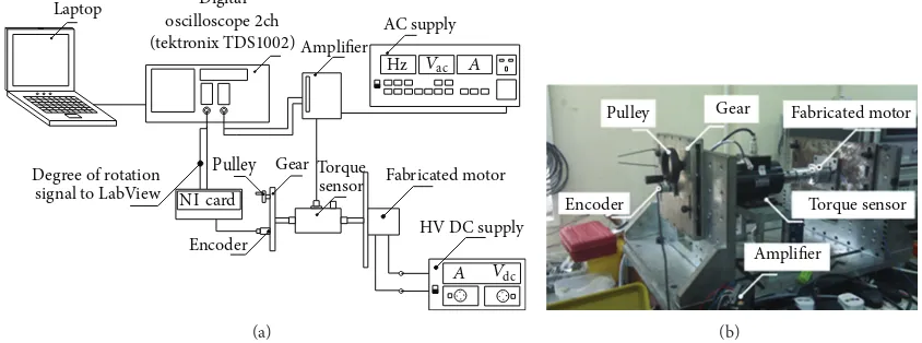
4.2. Experimental Evaluations. he fabricated best it DSIPM
with thick pole shoe for the same size and volume as that of the fabricated SSIPM is as shown inFigure 10.
(a) (b) (c)
Figure 10: Fabricated best it DSIPM with thick pole shoe motor. (a) Inner coil; (b) rotor; (c) assembled structure.
Laptop Digital
oscilloscope2ch (tektronix TDS1002)
Degree of rotation signal to LabView
Pulley Gear
NI card
Encoder
Amplifier
AC supply
Hz
Torque
sensor Fabricated motor
HV DC supply
Vac
Vdc
A A
(a)
Pulley Gear
Encoder
Fabricated motor
Torque sensor
Amplifier
(b)
Figure 11: Equipment setup for torque measurement. (a) Block representation; (b) experimental setup.
by a DC current to match the similar value of NI that was calculated in the FEA. As a result, the static torque is plotted along the rotor position in degree for one pitch positioning of
120∘. he measurement is varied from 0 At to 480 At.
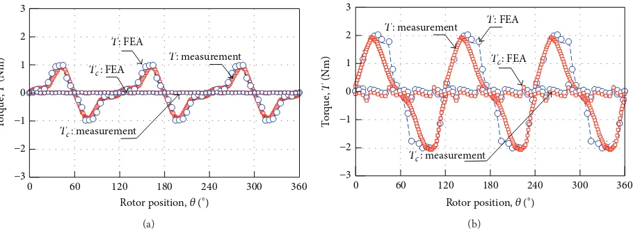
4.3. Comparative Evaluations. Figure 12 shows comparison
on torque characteristics of fabricated and simulated (FEA) of SSIPM and DSIPM with thick pole shoe. Results of fab-ricated SSIPM and DSIPM with thick pole shoe are in good agreement with the measurement result. It can be seen that the percentage error between simulation and measurement is less than 10%.
For inal comparison, motor constant square density�is used to quantify the level of performance. he motor constant square density has considered the torque, power, and volume of a particular motor which is good for comparison purposes. he motor constant square density can be expressed as
� = (���)2 [Nm2A2/W/m3] , (12)
where �� is the motor constant in [Nm/A/W(1/2)],� is the volume of the overall motor [m3]. Table 6 shows the district comparative evaluations for all motors that had been
developed in this research. It is evaluated that DSIPM with thick pole shoe is the best it that is investigated with bigger
�value of 15.
5. Conclusions
Interior permanent magnet single phase motor based on improvement of magnetic circuit is comprehensively inves-tigated. he torque components for the various proposed magnetic topology are designed and compared to derive the best structure. he optimal parameters value is derived based on analysis using FEA. he fundamental torque for the best it DSIPM with thick pole shoe exhibits double the torque value compared to conventional magnetic circuit due to the series magnetic circuit. he motor constant square density shows a performance improvement of 85.5% for the best it DSIPM with thick pole shoe better compared to the conventional magnetic circuit of the SSIPM. he proposed magnetic circuit structure is fabricated and experimentally evaluated.
Conflict of Interests
at
h
ema
tica
lP
ro
b
lem
s
in
En
gi
neer
in
g
13
Table 6: Comparative evaluation of various structures of the IPM.
Parameters SSIPM DSIPM DSIPM with thin pole shoe DSIPM with thick pole shoe Reference [19,20]
Numerical Measurement Numerical Numerical Numerical Measurement Numerical
�[A] 6 6 6 6 6 6 4
��[Ω] 3.0 3.0 3.0 3.0 3.0 3.0 6.25
�[m3]×10−5 4.75 4.75 4.75 4.75 4.75 4.75 4.75
��[Nm] 0.65 0.6 0.64 0.852 1.60 1.68 0.8
��[Nm/A] 0.108 0.1 0.106 0.142 0.267 0.28 0.2
��[Nm/A/m3]× 103 2.28 2.1 2.23 2.98 5.62 5.89 16.84
��[Nm/A/W(1/2)]× 103 10.8 10 10.6 14.2 26.7 28 0.02
T
Tc: measurement
T: measurement
Tc: measurement
T: measurement
Figure 12: Measurement characteristics of the fabricated motor (a) SSIPM with thick pole shoe. (b) DSIPM with thick pole shoe.
References
[1] S. Bentouati, Z. Q. Zhu, and D. Howe, “Inluence of design parameters on the starting torque of a single-phase PM brush-less DC motor,”IEEE Transactions on Magnetics, vol. 36, no. 5, pp. 3533–3536, 2000.
[2] S. Lizhi, F. Qi, and S. Jing, “Drive of single-phase brushless DC motors based on torque analysis,”IEEE Transactions on Magnetics, vol. 43, no. 1, pp. 46–50, 2007.
[3] W. Wang, H. Wang, and H. R. Karimi, “Study on the character-istics of electromagnetic noise of axial lux permanent magnet synchronous motor,”Abstract and Applied Analysis, vol. 2014, Article ID 764105, 8 pages, 2014.
[4] C. P. Liu, T. K. Lin, Y. H. Chang et al., “Performance of a single-phase DC brushless motor utilizing the ferromagnetic base material,”Journal of Magnetism and Magnetic Materials, vol. 209, no. 1–3, pp. 176–179, 2000.
[5] B. Singh and S. Singh, “State of the art on permanent magnet brushless DC motor drives,”Journal of Power Electronics, vol. 9, no. 1, pp. 1–17, 2009.
[6] H. B. Ertan, B. Daˇg, and G.-A. Capolino, “Calculation of param-eters of single-phase PM motor for design optimization,”IEEE Transactions on Energy Conversion, vol. 20, no. 3, pp. 538–548, 2005.
[7] M. Norhisam, K. Alias, R. N. Firdaus, S. Mahmod, N. Mariun, and J. Abdul Razak, “Comparison on thrust characteristic of linear oscillatory actuators,” in Proceedings of the IEEE International Conference on Power and Energy, pp. 470–475, Kuala Lumpur, Malaysia, November 2006.
[8] R. N. Firdaus, M. Norhisam, N. Mariun, I. Aris, M. Nirei, and H. Wakiwaka, “Torque characteristics of single phase brushless dc permanent magnet motor,”Journal of the Japan Society of Applied Electromagnetic and Mechanics, vol. 19, pp. S95–S98, 2011.
[9] C. C. Hwang, C. M. Chang, S. P. Cheng, C. K. Chan, C. T. Pan, and T. Y. Chang, “Comparison of performances between IPM and SPM motors with rotor eccentricity,”Journal of Magnetism and Magnetic Materials, vol. 282, no. 1–3, pp. 360–363, 2004. [10] T. J. Kim, S. M. Hwang, K. T. Kim, W. B. Jung, and C. U.
Kim, “Comparison of dynamic responses for IPM and SPM motors by considering mechanical and magnetic coupling,” IEEE Transactions on Magnetics, vol. 37, no. 4, pp. 2818–2820, 2001.
[11] C. Feng, X. Jing, G. Bin, C. Shukang, and Z. Jiange, “Double-stator permanent magnet synchronous in-wheel motor for hybrid electric drive system,”IEEE Transactions on Magnetics, vol. 45, no. 1, pp. 278–281, 2009.
[12] Y. Wang, M. Cheng, M. Chen, Y. Du, and K. T. Chau, “Design of high torque density double stator permanent brushless motors,” IEEE Transactions on Magnetics, vol. 5, no. 3, 313327 pages, 2010. [13] S. Niu, K. T. Chau, J. Li, and W. Li, “Eddy-current analy-sis of double-stator inset-type permanent magnet brushless machines,”IEEE Transactions on Applied Superconductivity, vol. 20, no. 3, pp. 1097–1101, 2010.
[14] M. Norhisam, S. Ridzuan, R. N. Firdaus, C. V. Aravind, H. Wakiwaka, and M. Nirei, “Comparative evaluation on power speed density of portable permanent magnet generator for agricultural application,”Progress in Electromagnetics Research, vol. 129, pp. 345–363, 2012.
[15] M. Norhisam, M. Noraiza, M. Shaiq et al., “Design and analysis of slot type embedded permanent magnet generator,”Journal of Industrial Technology, vol. 18, no. 1, pp. 1–14, 2009.
[16] G. H. Kang, J. Hur, H. G. Sung, and J. P. Hong, “Optimal design of spoke type bldc motor considering irreversible demag-netization of permanent magnet,” in Proceedings of the 6th International Conference on Electrical Machines and Systems, pp. 234–237, 2003.
[17] D. Lin, P. Zhou, and Z. J. Cendes, “Analytical prediction of cogging torque in spoke type permanent magnet motors,” in Proceedings of the International Conference on Electrical Machines, pp. 1–5, September 2008.
[18] K. Boughrara, R. Ibtiouen, and T. Lubin, “Analytical prediction of magnetic ield in parallel double excitation and spoke-type permanent-magnet machines accounting for tooth-tips and shape of polar pieces,”IEEE Transactions on Magnetics, vol. 48, no. 7, pp. 2121–2137, 2012.
[19] S. Ahmed and P. Leley, “Study of the impact of asymmetrical stator pole arc on the cogging torque for single phase perma-nent magnet BLDC motor,” inProceedings of the International Conference on Electric Power and Energy Conversion Systems, pp. 1–4, November 2009.
[21] C. V. Aravind, M. Norhisam, I. Aris, M. H. Marhaban, and M. Nirei, “Electromagnetic design and FEM analysis of a novel dual air-gap reluctance Machine,”Progress in Electromagnetic Research, vol. 140, no. 5, pp. 523–544, 2013.
[22] C. A. Vaithilingam, M. Norhisam, M. R. Zare, I. Aris, and M. H. Marhaban, “Computation of electromagnetic torque in a double rotor switched reluctance motor using energy methods,” Energies, vol. 5, pp. 4008–4026, 2012.
[23] R. N. Firdaus,Improvement of magnetic circuit for development of high torque density single phase brushless DC permanent magnet motor [Ph.D. thesis], University Putra Malaysia, 2013. [24] A. Kameari, “Local force calculation in 3D FEM with edge
Submit your manuscripts at
http://www.hindawi.com
Hindawi Publishing Corporation
http://www.hindawi.com Volume 2014
Mathematics
Journal ofHindawi Publishing Corporation
http://www.hindawi.com Volume 2014 Mathematical Problems in Engineering
Hindawi Publishing Corporation http://www.hindawi.com
Differential Equations International Journal of
Volume 2014 Hindawi Publishing Corporation
http://www.hindawi.com Volume 2014
Hindawi Publishing Corporation
http://www.hindawi.com Volume 2014
Hindawi Publishing Corporation
http://www.hindawi.com Volume 2014
Mathematical PhysicsAdvances in
Complex Analysis
Journal of Hindawi Publishing Corporationhttp://www.hindawi.com Volume 2014
Optimization
Journal ofHindawi Publishing Corporation
http://www.hindawi.com Volume 2014
Combinatorics
Hindawi Publishing Corporation
http://www.hindawi.com Volume 2014
International Journal of Hindawi Publishing Corporation
http://www.hindawi.com Volume 2014
Journal of
Hindawi Publishing Corporation
http://www.hindawi.com Volume 2014
Function Spaces
Abstract and Applied Analysis
Hindawi Publishing Corporation
http://www.hindawi.com Volume 2014
International Journal of Mathematics and Mathematical Sciences
Hindawi Publishing Corporation http://www.hindawi.com Volume 2014
The Scientiic
World Journal
Hindawi Publishing Corporation
http://www.hindawi.com Volume 2014
Hindawi Publishing Corporation
http://www.hindawi.com Volume 2014
Discrete Dynamics in Nature and Society Hindawi Publishing Corporation
http://www.hindawi.com Volume 2014
Hindawi Publishing Corporation
http://www.hindawi.com Volume 2014
Discrete Mathematics
Journal ofHindawi Publishing Corporation
http://www.hindawi.com Volume 2014 Hindawi Publishing Corporation
http://www.hindawi.com Volume 2014