i
EVALUATION OF A PERODUA KANCIL ENGINE MOUNTING SYSTEM
MOHD IZARIN BIN ISHAK
This report is represented in partial fulfillment of the requirement for the Degree of Bachelor of Mechanical Engineering (Automotive)
Faculty of Mechanical Engineering Universiti Teknikal Malaysia Melaka
ii
“I hereby declare that I have read this thesis and in my opinion this report is sufficient in terms of scope and quality for award of degree of Bachelor of
Mechanical Engineering (Automotive).”
Signature: ... Supervisor I: Mr. Mohd Hanif Bin Harun Date: 23 May 2011
Signature: ...
Supervisor II: Mr. Wan Mohd Zailimi bin Wan Abdullah @ Zakaria
iii
“I hereby declare that the work in this report is my own work except for summaries and quotations that I have mentioned its sources.”
Signature: ……….
iv
To my beloved parents,
Mr. Ishak Bin Mohd and Mrs. Maison Binti Mohd Rafie My siblings
And also
v
ACKNOWLEDGEMENTS
Alhamdullillah...
Grateful to Almighty for with His divine grace, I have successfully completed this Projek Sarjana Muda 1 with great success. By the end of my project, I have produced a report which is compulsory for all students.
I would like to thank my supervisors Mr. Mohd Hanif Harun for his input and support over the duration of this project. Thank you so much for your cooperation in each meeting we make, really appreciate your effort.
I would like to take this opportunity to thank my parents, for their comfort and support through all my hard work, and the values they have taught me. Thanks also to my brother for providing happiness and inspiration to my life.
vi
ABSTRACT
vii
ABSTRAK
viii
CONTENTS
CHAPTER TITLE PAGE
DECLARATION ii
DEDICATION iii
ACKNOWLEDGEMENTS v
ABSTRACT vi
ABSTRAK vii
CONTENTS viii
LIST OF FIGURES xi
LIST OF TABLE xiii
LIST OF SYMBOL xiv
LIST OF ABBREVIATION xviii
LIST OF APPENDICES xix
CHAPTER I INTRODUCTION 1
1.1 Background 1
1.2 Problem Statement 2
ix
1.4 Project Scope 3
1.5 Gantt Chart 4
1.6 Project Outline 6
1.7 Project flow chart 7
CHAPTER II LITERATURE REVIEW 8
2.1 Engine Mounting System 8
2.2 Type of Engine Mounts 9
2.2.1 Passive Engine Mounts 9 2.2.2 Semi-active Engine Mount 10 2.2.3 Active Engine Mount 11 2.3 Previous study on Active Engine Mounting 14
System
2.4 PID Controller 15
CHAPTER III METHODOLOGY 18
3.1 Flow chart for PSM 1 and PSM 2 19
3.2 Equation of motion 20
3.2.1 Passive Engine Mounting (Single DOF) 20 3.2.2 Passive Engine Mounting (3 DOF) 23 3.2.3 Active Engine Mounting (Single DOF) 28 3.2.4 Active Engine Mounting (3 DOF) 29 3.2.5 Skyhook Engine Mounting 31 3.3 Overall Block Diagram of Engine Mounting 32
x
CHAPTER IV RESULT AND ANALYSIS 33
4.1 Simulation Result 33
4.1.1 Parameter 34
4.1.2 Vertical Motion 34
4.1.3 Pitch Motion 37
4.1.4 Roll Motion 38
4.1.5 Transmitted Force 39
4.2 Simulation Analysis 40
4.3 Simulation Validation 41
4.3.1 Parameter 41
4.3.2 Vertical Motion 42
4.3.3 Angular Motion 43
CHAPTER V DISCUSSION 44
5.1 Modeling Assumption 44
5.2 Simulation Result 45
5.2.1 Vertical Motion 45
5.2.2 Pitch Motion 46
5.2.3 Roll Motion 47
5.2.4 Transmitted Force 47
CHAPTER VI CONCLUSION AND RECOMMENDATION 48
6.1 Conclusion 48
6.2 Recommendation 49
REFERENCES 50
xi
LIST OF FIGURES
NO. TITLE PAGE
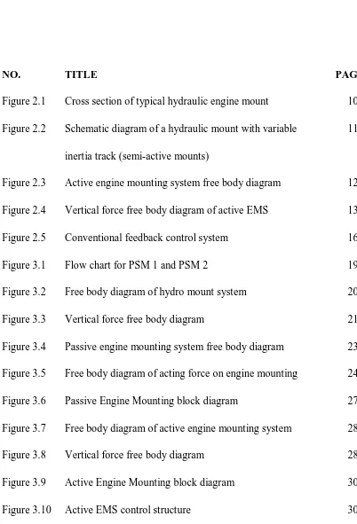
Figure 2.1 Cross section of typical hydraulic engine mount 10 Figure 2.2 Schematic diagram of a hydraulic mount with variable 11
inertia track (semi-active mounts)
xii
Figure 3.11 Skyhook Engine Mounting block diagram 31 Figure 3.11 Overall Engine Mounting System block diagram 32 Figure 4.1 Graph of Excitation Force versus Time 34 Figure 4.2 Graph of Vertical Acceleration versus Time 34 Figure 4.3 Graph of Vertical Displacement versus Time 35 Figure 4.4 Graph of Zef Displacement versus Time 35 Figure 4.5 Graph of Zerr Displacement versus Time 36 Figure 4.6 Graph of Zel Displacement versus Time 36 Figure 4.7 Graph of Zer Displacement versus Time 37 Figure 4.8 Graph of Pitch Acceleration versus Time 37 Figure 4.9 Graph of Pitch Angle versus Time 38 Figure 4.10 Graph of Roll Acceleration versus Time 38 Figure 4.11 Graph of Transmitted Force versus Time 39 Figure 4.12 Excitation force from this project 41 Figure 4.13 Excitation force from T. Q. Tanh (2006) 41 Figure 4.14 Vertical acceleration from this project 42 Figure 4.15 Vertical acceleration from Tanh T. Q. (2006) 42 Figure 4.16 Vertical Acceleration from Ye L. T. (2009) 42 Figure 4.17 Pitch Angle from this project 43 Figure 4.18 Pitch Angle from Andika A. W. (2009) 43 Figure A Discrete PID Controller parameter 54 Figure B Discrete PID Controller result after tuning 55
xiii
LIST OF TABLES
NO. TITLE PAGE
Table 2.1 Effects of independent P, I and D tuning 17
Table 3.1 Parameters for simulation 21
Table 3.2 PID Controller Parameters 29
xiv
LIST OF SYMBOLS
P(t) = Excitation force Me = Engine mass
Mu = Unbalance mass
r = Radius of the rotation ω = Speed of rotation
Fs = Spring force
Fd = Damper force
ks = Spring constant
Cs = Damping constant
Zs = Engine unit displacement
Zu = Chassis unit displacement
s
Z = Engine unit velocity
u
Z = Chassis unit velocity
s
Z = Engine unit acceleration
xv
Fsf = Front spring force
Fsrr = Rear spring force
Fsr = Right spring force
Fsl = Left spring force
Fdf = Front damper force
Fdrr = Rear damper force
Fdr = Right damper force
Fdl = Left damper force
Fcf = Front skyhook force
Fcrr = Rear skyhook force
Fcr = Right skyhook force
Fcl = Left skyhook force
P = Track width L = Wheelbase length ksf = Front spring constant
ksrr = Rear spring constant
ksr = Right spring constant
ksl = Left spring constant
Csf = Front damping constant
Csrr = Rear damping constant
Csr = Right damping constant
Csl = Left damping constant
xvi
Zsrr = Rear engine unit displacement
Zsr = Right engine unit displacement
Zsl = Left engine unit displacement
Zuf = Front chassis unit displacement
Zurr = Rear chassis unit displacement
Zur = Right chassis unit displacement
Zul = Left chassis unit displacement
s f
Z = Front engine unit velocity
sr r
Z = Rear engine unit velocity
sr
Z = Right engine unit velocity
sl
Z = Left engine unit velocity
u f
Z = Front chassis unit velocity
ur r
Z = Rear chassis unit velocity
u r
Z = Right chassis unit velocity
u l
Z = Left chassis unit velocity
Mp = Pitching moment
Mr = Rolling moment
Ip = Inertia in pitching
Ir = Inertia in rolling
= Pitching angle
xvii = Roll angle
= Roll rate
= Roll acceleration
xviii
LIST OF ABBREVIATION
AEM = Active Engine Mounting ACV = Active Vibration Control DOF = Degree of freedom EMS = Engine Mounting System FF = Feedforward
xix
LIST OF APPENDICES
NO. TITLE PAGE
1
CHAPTER I
INTRODUCTION
This chapter will provide information about the background, problem statement, objective, project scope, project Gantt chart, project outline and project flow chart of this project.
1.1 Background
2 Kancil 850 EZ engine, it has four mounts which located at the front, right, left and rear. Generally conventional vehicle like Perodua Kancil use Passive Engine Mounting System (EMS).
1.2 Problem Statement
Worn engine mounts will bring much effect. The increasing of noise and vibration was the symptoms as well as increased pedal pressure or slower respons to driver input. It was because some linkage happens in controller linkage such as at throttle and transmission. In some cases, the throttle linkage can be jammed, resulting in unintended acceleration. A broken engine mounts inside a car with belt-driven, water pump mounted fan, may cause the engine to rotate forward and hit the radiator with the fan blades. Besides, problem with the engine mounts can lead to a chain reaction down the driveline. Broken engine mounts also will lead to misalignment of the driveshaft.
1.3 Objective
3 1.4 Project Scope
4
No. Task Week
1 2 3 4 5 6 7 8 9 10 11 12 13 14
1 Choosing title
2 1st meeting with Supervisor 3 Gantt Chart
4 Prepare Technical Report for
Chapter 1 : Introduction Background Problem Statement Objective Projest Scope 5 Study the Matlab Simulink software 6 Review study of an engine mounting
system
7 1st PSM presentation 8 Prepare Technical
Report for Chapter 2 :
Literature Review Theory Mathematical model Engine mounting system
9 Develop mathematical equation
10 Prepare Technical Report for Chapter 3 and Chapter 4 (Methodology and Conclusion)
11 2nd PSM presentation
12 Submission of technical report 1.5 Gantt Chart
5 Project Gantt chart PSM 2
No. Task Week
1 2 3 4 5 6 7 8 9 10 11 12 13 14 15 16 1. Repair previous PSM1 report
2. Perform mathematical equation in MATLAB Simulink
3. Gathering data for model 4. Create simulation
5. Predict the performance of engine mounting system