ii
DECLARATION
“I hereby declare that the work in this thesis is my own except for summaries and quotations which have been duly acknowledged.”
Signature: ……….. Author: LEE SEK ENN
iii
iv
ACKNOWLEDGEMENT
First of all, I would like to express my deepest appreciation to my supervisor, Dr. Cheng See Yuan, and Dr Soo Yew Guan for providing me explanations and guidances me throughout the entire PSM process. Without the sharing and help from him, it would be extremely difficult to proceed in this study. Therefore, it is definitely an honor of mine to be able to have him as my supervisor.
Secondly, I would also like to thank my university, Universiti Teknikal Malaysia Melaka (UTeM), and my faculty, Faculty of Mechanical Engineering, for giving me an opportunity to gain more knowledge in the last four years.
Furthermore, I would like to express my sincere gratitude to my friends and Hoo who accompanied me throughout the entire learning process in UTeM. They gave me a lot of advices and encouragement. I may have hard time struggling in my studies if I did not meet them.
v
ABSTRACT
vi
ABSTRAK
vii
TABLE OF CONTENTS
CHAPTER TITLE PAGE
DECLARATION ii
ACKNOWLEDGEMENT iv
ABSTRACT v
ABSTRAK vi
TABLE OF CONTENTS vii
LIST OF FIGURES x
LIST OF TABLES xii LIST OF SYMBOLS xiii LIST OF APPENDIXES xiv
CHAPTER 1 INTRODUCTION
1.1 Background 1
1.2 Problem Statement 2
1.3 Objectives 2
1.4 Scope 2
CHAPTER 2 LITERATURE REVIEW
2.1 Research Background 3
2.2 Overview of Inspection System 3
2.3 Photogrammetry 5
2.3.1 Close range Photogrammetry 7 2.3.2 Technical Issues of Photogrammetry 8
2.3.3 Photogrammetric Cameras 9
2.3.4 SLR Cameras 10
viii
2.3.6 Accuracy and Verification 11 2.4 Automated Inspection on Moving 11
Conveyor
2.4.1 System Set-up for the Non 12 Contact Measurement Approach Structure 2.4.2 Automated Headlamp Lens Inspection 13
2.4.3 System Configuration 15
2.5 Digital Image Matching 15
2.6 Design for Actuator 17
2.7 Design of Speed Controller for DC Motor Drive 18 2.7.1 Mathematical Modeling of DC Motor Drive 18
2.8 Servo Motor 19
CHAPTER 3 METHODOLOGY
3.1 Overview of measuring system components 25
3.1.1 Parallel Interface 26
3.1.2 Camera Module 26
3.1.3 Camera Pan and Tilt 27
3.1.4 Direction of Movement 27
3.1.5 Software 27
3.2 Selection of Measurement 27
3.2.1 Ac Servo Motor Controller 27 3.2.2 Linear Electric Actuator 28
3.2.3 Raspberry Pi 31
3.2.4 Proximity Sensor 33
3.3 Method of Operation 34
3.3.1 Initialization 34
3.3.2 Direct Measurement Approach 34 3.3.2.1 Speed of Conveyor Belt 35 3.3.2.2 Speed of Linear Actuator 36 3.3.3 Analysis of Linear Actuator through Test 38
Mode
3.3.4 Targeting Object 39
ix
CHAPTER 4 RESULT AND ANALYSIS 41
4.1 Program Written in Program Operation Mode 41 4.2 Images Captured by Running the Program 44
CHAPTER 5 DISCUSSION 49
CHAPTER 6 CONCLUSION AND RECOMMENDATION 51
REFERENCES 52
APPENDIX A 56
APPENDIX B 58
x
LIST OF FIGURES
NO. TITLE PAGE
2.1 Aerial photogrammetry . 6
2.2 Close range photogrammetry . 7
2.3 Examples of photogrammetric cameras 9
2.4 Examples of photogrammetric multi- camera systems 9
2.5 Examples of digital SLR cameras 10
2.6 Visual classification setup in an industrial setting 12 2.7 Configuration for in line inspection calibration 12
2.8 Plastic lens with punctual defect 14
2.9 The proposed sensor planning system 14
2.10 The optimal system configuration which required symmetric 15 angle of 45⁰ between cameras and the similar positioning for the lamps. 2.11 Schema of the algorithm for reconstruction of surface with 17
discontinuity by digital image matching technique
2.12 Block diagram of closed loop control of DC motor 19
2.13 Design of Motor- Stator 23
2.14 Design of Motor – Rotor 23
2.15 Design of Motor – Encoder 24
3.1 Schematic diagram of setup configuration 25
3.2 Overview of setup configuration 26
3.3 Ac Servo Motor 28
3.4 Electric linear actuator 30
3.5 Raspberry Pi and Raspberry Pi camera mounted on the special custom 32 made table
3.6 Proximity sensor light up when the object pass through it 33
xi
3.8 Jog test mode 36
3.9 Positioning test mode 36
3.10 High Speed Monitor and positioning test mode 37
3.11 Speed graph of linear actuator with highest speed. 38 3.12 Speed graph of linear actuator with highest speed 39
3.13 Pin number of the controller 40
4.1 Program write in Program Operation Mode 43
4.2 Actuator start moving in backward direction 43
4.3 Actuator start moving in forward direction 43
4.4 1st set of image of object being transported on conveyor belt at 1200r/min 44 4.5 2nd set of image of object being transported on conveyor belt at 1200r/min 44 4.6 3rd set of image of object being transported on conveyor belt at 1200r/min 45 4.7 1st set of image of object being transported on conveyor belt at 200r/min 45 4.8 2nd set of image of object being transported on conveyor belt at 200r/min 45 4.9 3rd set of image of object being transported on conveyor belt at 200r/min 46 4.10 Comparison of 1st set image between stationary and moving 46
actuator at 1200r/min
4.11 Comparison of 2nd set image between stationary and moving 47 actuator at 1200r/min
4.12 Comparison of 3rd set image between stationary and moving 47 actuator at 1200r/min
4.13 Comparison of 1st set image between stationary and moving 48 actuator at 200r/min
4.14 Comparison of 2nd set image between stationary and moving 48 actuator at 200r/min
xii
LIST OF TABLES
NO. TITLE PAGE
2.1 Comparison types of driving devices . 20
2.2 Comparison Table of Motors . 21
xiii
LIST OF SYMBOLS
rpm = Revolution per minute
W = Watt
Hz = Hertz
mm = Millimeter cm = Centimeter MB = Mega Byte
a = Acceleration, mm/s2 ms = Acceleration, ms
s = Second
xiv
LIST OF APPENDIXES
NO. TITLE PAGE
A Application Summary of Servo Motor 56
B Signal Wiring of AC Servo Motor 58
1
CHAPTER 1
INTRODUCTION
1.1 Background
2
1.2 Problem Statement
To speed up production rate and improve product quality, products inspection has to be carried out with higher accuracy at shorter duration of time. Thus, non– contacting 3D modeling reconstruction such as photogrammetry appear to be a good avenue (Uffenkamp, n.d.). However, in a continuous manufacturing process, a product is being delivered in a continuous manner. Dealing with a moving target causes a motion effect (i.e. Blurring) on the acquired images (Zappa et al., 2014). Therefore, a controllable electric linear actuator that can move simultaneously with the conveyer belt is necessary. By doing so, camera mounted on the electric linear actuator can move at the same speed as the rate of product that being delivered on the conveyer belt. Hence, blurring of image eliminated.
1.3 Objectives
i) To optimize the AC Servo Motor controller of motorized linear actuator for image base 3D modeling application
ii) To design varies mechanisms of controlling the speed, timing and positioning linear slider of image capturing device of photogrammetry.
iii) To access the performance of each control mechanisms.
1.4 Scope
3
CHAPTER 2
LITERATUREREVIEW
2.1 Research Background
Standard method for complex 3D measurement tasks need to have object with a high number of object points. Close range photogrammetry offered potential measurement with convergent multi- image configurations (Luhmann, 2010). Inspection of incoming parts with no human interface can be done but this required at the finished assemblies and photogrammetry is usually done when the products is in static condition. To make it in time inspection at the early stage without stopping the production line, actuators to run corresponding with the conveyor belt is designed for the visual inspection. However highly precision position and speed controls are needed especially in motion control equipment (Rashidi et al., 2015). Types of actuators are compared of its function and advantages in application. .Furthermore, controller should have design with load/ friction compensation, disturbance rejection against parameter variations in addition to accuracy (Rashidi et al., 2015). Basically the objective of controller is to make system to reach the optimum position.
2.2 Overview of Inspection System
4
approach of inspection method uses measurement such as ruler, calipers, and meter ruler and so on. Therefore manufacturers look for reliable and consistent automated visual inspection of their products to reduce manual involvement in inspection. Not only this, labor intensive methods will result in increase of manufacturing lead time and production cost, as well as significant delay in detecting the defects (Fundamentals et al., n.d.).
Basically, finish inspection and in-line inspection are the two main inspection performed by machining industries. Finish inspection can only performed the work at the end of the machining process in a special quality room where in- line inspection is performed at the production line (Ayub et al., 2014).
The advantages of in-line inspection are the identification deviations from the nominal values, detection absence of vital parts of properties and detection products out of tolerance at the early stage in manufacturing process to prevent from further machining, handling, assembly, etc. In addition, information on deviations from target values may be fed back to process (Ayub et al., 2014).
Among those inspection processes, visual inspection is another kind of inspection approach that mainly deals with surface quality and maximum defect size. Defects on surfaces, such as cracks, corrosion, damaged part on a component assembly also part of visual inspection (Li & Gu, 2004). In the meantime, there are quite of areas visual inspection have extended to. For an example, areas of robot guidance, inspection of incoming parts or finished assemblies in application of inspection, part identification, guidance and control (Ayub et al., 2014). Significant advantages of an optical visual inspection are it can executed very fast with no human interference and constant, thus 100% monitoring of the production can be achieved (Kosmopoulos & Varvarigou, 2001). Lest not, direct input of image information into computers is the development of fully automated photogrammetric measurement (as a part of visual inspection). This discover been a possibility for quality control which would be benefit in industrial inspection (Clarke et al., n.d.).
5
biology, archeology, architecture, automotive and aerospace engineering, as well as accident reconstruction have practiced photogrammetry (Jiang et al., 2008). According to Satorres Martínez et al., (2009), different types of defects are detected based on the design of algorithms which are more towards its geometry and dimensions. Large variety of industrial application areas also apply photogrammetric system, including;
Automotive manufacturing, for car body deformation measurement, control of supplier parts, adjustment of tooling and rigs, establishment of control point networks, crash testing, etc.;
Aerospace industry, for measurement and adjustment of mounting rigs, antenna measurement, part-to-part alignment, etc.;
Wind energy systems for deformation measurements and production control; Engineering and construction, for measurement of water dams, tanks, plant
facilities, etc.
2.3 Photogrammetry
By using camera, digital representing of real object in form of point cloud is a technique of photogrammetry (Daaam, 2010). In other word, reliable information about the properties of surfaces and objects is able to obtain through photogrammetry without physical contact with the objects. The name “photogrammetry” is derived from three Greek words phos or phot which means light, gramma means letter or something drawn, and metrein is the noun of measure (Schenk, 2005).
6
from the three dimensional coordinates of the points of interest (“Geodetic Systems, Inc,” n.d.). Second type would be monoscopic photogrammetry (also called as single image photogrammetry) where information of objects is presented by using mono-plotting methods (Marinov, 2003).
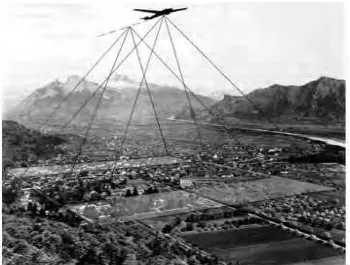
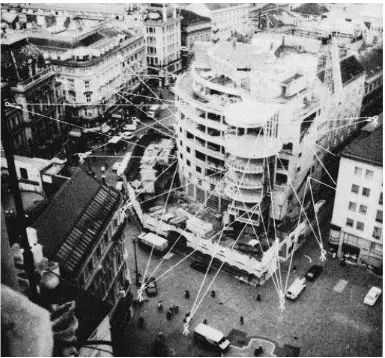
[image:19.595.146.496.338.603.2]On the basic, photogrammetry also divided into two categories: aerial and terrestrial photogrammetry. Images such as topographic maps and land use details acquired via overhead shots from an aircraft are known as aerial photogrammetry (Fig. 2.1). Terrestrial photogrammetry is further defined as close range photogrammetry (Fig. 2.2), an approach where camera generally pointing towards the center of the object with highly convergent camera orientations when the object size and the camera distance are both less than 100m (Jiang et al., 2008).
7
Figure 2.2: Close range photogrammetry. (Source: Marinov, 2003)
2.3.1 Close range Photogrammetry
8
2.3.2 Technical Issues of Photogrammetry
To form an efficient and economic system, number of technical components required to succeed use of photogrammetry in industry. Therefore, components and related technical issues summaries as the following list:
Imaging sensor: resolution (number of pixels), acquisition and data transfer speed, camera stability, synchronization and etc.;
Targeting and illumination: interested object featured, target shape and size, and measurement volume;
Image configuration: number of camera stations, desired measurement accuracy, redundancy, robustness, self- calibration ability, and self- control of orientation and calibration;
Image processing: automation of target recognition and identification, sub-pixel measurement of target center, multi-image, matching approaches, and feature tracking;
3D reconstruction: 3D coordinates determination method (e.g. spatial intersection, bundle adjustment) and error statistics;
Data interfaces: integration into CAD/ CAM environments, machine and data interfaces and etc.;
Verification of accuracy: reference bodies, reference data, standards and guidelines and acceptance tests.
Setup of complex tasks is illustrated in above lists for an appropriate design, operation of close-range industrial photogrammetry systems. Besides, basic camera concepts, system designs and measurement tasks for industrial photogrammetry also presented. An overview of recent technology and applications provided rather than comprehensive coverage due to large variety of applications and system configurations is discussed (Luhmann, 2010).
9
2.3.3 Photogrammetric Cameras
[image:22.595.216.497.307.482.2]Cameras with stable interior orientation and high accuracy are demanded to reduce need of periodic or on-the-job calibration, and technical possibility for simultaneous camera calibration. Besides the classical ‘metric camera’, rarely few cameras are mainly for photogrammetry application. However, limitation of ‘metric camera’ is it only is used in conjunction with the desired accuracy level of camera. Photogrammetric cameras (Fig. 2.3 and Fig. 2.4) are designed for high- accuracy industrial metrology. In the meantime, the integrated processors enable 3D measurements in off-line (1 camera) or on-line (2 camera) mode (Luhmann, 2010).
Figure 2.3: Examples of photogrammetric cameras. (Source: Luhmann, 2010).
[image:22.595.112.510.578.718.2]10
2.3.4 SLR Cameras
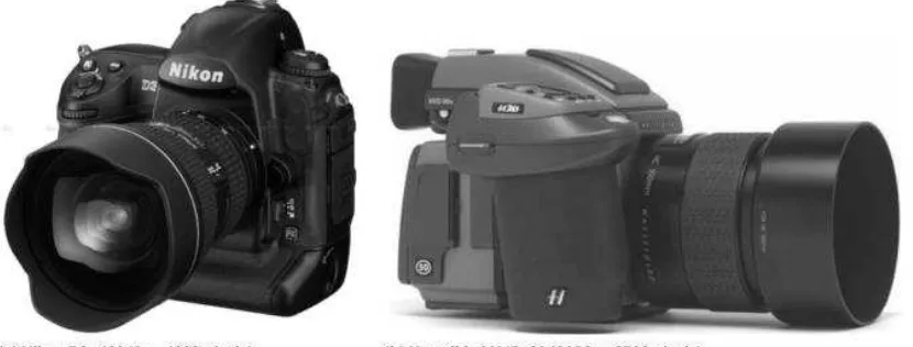
[image:23.595.115.530.306.464.2]High- resolution digital SLR cameras with sensors between 10 and 60 Megapixel are designed for fast and simple photogrammetric work because of its range of exchangeable lenses, high capacity storage devices and powerful batteries. Somehow, camera calibration is an important step in the complete process chain as their mechanical stability is usually poor and with changing interior orientation (Luhmann, 2010). Classical small format (35mm SLR) are offered by companies such as Nikon, Canon and Sony are mainly used for off-line applications. The two sample cameras are shown in Fig. 2.5.
Figure 2.5: Examples of digital SLR cameras. (Source: Luhmann, 2010)
2.3.5 Camera Calibration
Since accuracy is directly related to sensor quality and correct modeling of interior orientation, camera calibration is an essential of photogrammetric systems in industrial application (Luhmann, 2010). Somehow, there would be some difficulties faced in calibration as stated in following cases:
Camera geometry unstable during image acquisition (e.g. gravity effects) Geometric configuration of images does not allow bundle adjustment with self-
11
Objects does not provide enough information (e.g. points, distances) for calibration
Besides, three or more control points as the datum of object can be introduces as well as introducing shape constraints in photogrammetric orientation (Luhmann, 2010). Otherwise, image-wise of the camera will be calibrated if the mechanical instability of the camera is worse than the required accuracy level. As long as the imaging configuration consists of enough well distributed images, the position of perspective center is usually adjusted for each image while the distortion values are kept constant for all images as to enhance the accuracy. Furthermore, precision of camera calibration can be determined from precision of image and object points, or by standard deviations of camera parameters (Luhmann, 2010).
2.3.6 Accuracy and Verification
Two most important practical considerations are the specified accuracy of an industrial measurement system and the achieved accuracy within a real project. Final accuracy figures can be manipulated simply by increasing the number of observations in many photogrammetric applications. Furthermore, photogrammetric measured distances are compared to their calibrated nominal length for the accuracy test. Further developments of high precision industrial close range photogrammetry is challenging in industrial photogrammetry (Luhmann, 2010).
2.4 Automated Inspection on Moving Conveyor