0HDVXUHPHQWRI/RZ)UHTXHQF\6LJQDORI
3RZHU*ULG8VLQJ$UGXLQR
Mohd Firdaus bin Mohd Ab Halim, Mohamad
Haniff Harun, Khalil Azha Mohd Annuar,
Suziana Ahmad and Mohd Hanif Bin Che Hasan
Research Group Creative, Innovative and Technology,
Faculty of Engineering Technology, Universiti Teknikal Malaysia Melaka (UTeM), 76100 Durian Tunggal, Melaka,Malaysia
E-Mail: [email protected]
Abstract –The range of the frequency to be measured by a measurement device depends on the purpose of performing the measurement. The frequency measurement device is built specifically according to its range while the price of the device is proportional to its functions. In this paper, a low frequency measurement device to monitor grid frequency is designed using Arduino technology. All aspects of the design from the software to hardware is explained. This device costs less than 100 US Dollar and it is capable to perform data logging for data analysis. The frequency range for the device is between 45 Hz to 60 Hz with 0.003 Hz resolution. This paper also discuss the standard commercial measurement device in power system and Arduino capabilities. The measurement data from the device is analyze for its accuracy and reliability.
Keywords: Arduino, grid frequency monitoring, zero-crossing algorithm
I. INTRODUCTION
Frequency of a signal is measured in Hertz that is for a continuous sinusoidal signal sin (x), the frequency can be determine by knowing the period of the signal. In most cases the engineer does not know the exact function of the signal but the signal can be categorized according to its behavior pattern either sinusoidal, square or triangle wave. Most of the countries in European Continent use 50 Hz as the standard mains frequency. From power plant to the domestic user, the electricity is transmitted in sinusoidal pattern of 50 Hz. In this paper, the AC source of power outlet is set to be the test signal for the measurement device. According to European Network of Transmission System Operators for Electricity (ENTSO-E), the monitoring device of the mains frequency resolution should be as small as 0.01 Hz in order to see if any frequency deviation occurs [1]. Therefore, the test signal nominated here would be perfect to evaluate the measurement device functionality and performance.
In the past, measurement devices act as a troubleshooting tools for electrical engineers. The complexity of electrical system promotes the idea of
parameters monitoring and data logging. Understanding the behavior of any system through its main parameters ensures the stability and reliability of the system. An obvious example of a complex system which requires continuous monitoring is the electrical transmission grid.
II. COMPUTING FREQUENCY VIA ARDUINO
A. Technology and Arduino
Technology moves very fast as human strive to build the world a better place to live. The most important technology in the past decade is computer. Its creation opens up the opportunity for programmers to create many extraordinary software and application which human have a dull life without it such as computer games, communication software and etcetera. In order to increase the capability of the technology, the development software and operating system are available without licensing nor authorization. Arduino is one of the tools which is designed purposely to give more freedom to the user onto how they wanted the tools to behave. The only capital the user have to spend is on the microcontroller hardware [2].
The information of how to use the platform and the example of the program can be obtained easily in the main Arduino website. Arduino offers wide range of boards, kits, shields and accessories that can be used based on the user’s goal. Most Arduino product consist of basic microcontroller capabilities such as Analog to Digital Converter (ADC), PWM input, SRAM, standard clock speed of 16 MHz from Atmel chip and sufficient AC and DC Input/Output pins. Arduino Uno is one of Arduino boards that can be used to perform advance computation on the input signal with acceptable processing time and performance. It can perform a basic real time data monitoring. It also one of the cheapest board in Arduino family.
B. Arduino Frequency Computation
conversion is factored down because the ADC computation uses 2/3 of the ADC cycle time. Figure 1 shows the hardware setup to read ADC values with function generator as the input.
Zero-crossing method counts the number of ADC conversion from the first zero-crossing encounter to the successive zero-crossing encounter. Since the ADC rate is known, the period and the frequency of the signal can be calculated easily. Considering the test signal we set to use, the frequency of the signal is calculated using zero-crossing technique yield the result as in Table 1.
TABLE 1 Measurement Result Based On Zero-Crossing Method
The resolution of the result is unacceptable for this case. The rate of ADC conversion at pre-set value of 125 kHz alone could not yield at least 0.01 Hz of resolution. Increasing the ADC conversion rate to 250 kHz doubles the resolution of the frequency to 0.14 Hz, which is still far from the targeted accuracy. According to the literature notes of the microcontroller, “the ADC accuracy also depends on the ADC clock. The recommended maximum ADC clock frequency is limited by the internal DAC in the conversion circuitry. For optimum performance, the ADC clock should not exceed 200 kHz” [3]. Hence it is not recommended to consider altering the ADC rate to achieve our goal.
Linear interpolation can be employed to increase the resolution of the measurement. The ADC values after zero-crossing is not always constant. It can be any number between 0 to 1024. This random error occurs when the sampling frequency is not fast enough to cover the whole range of measurement value. By keeping the ADC values at both zero- crossing encounter, the error can be calculated and eliminated from the frequency calculation. Linear interpolation of the two successive values for this test signal increases the resolution by the factor of ¨ times where ¨ is the largest differences found during the transition of the signal from zero to a
between two occurrences.
TABLE 2 Measurement Result after Interpolation
Number of Result Number of Cycle Expected Result (Hz)
1-11 171 50.413 േį177 ×
οభ
12-23 172 50.120 േį178 ×
οమ
24-36 173 49.830 േį179 ×
οయ
By assuming
௧ the change of the signal magnitude over time is equal at the region of zero-crossing, interpolation error, İ exist in the calculation shown in equation (1).
For the case of data in Table 2, the result yield İ = 0.002 Hz which is acceptable. The frequency calculation program also assume that the ADC rate is performing consistently, which is 0.116 ms per conversion which is not always the case in live measurement. Based on ADC rate trial experiment, there are 0.5 % chance that the ADC rate perform 0.008 millisecond slower at one cycle before resume to the regular rate. This differences can also be neglected because it yield insignificantly low error.
ɂൌ௧Ȃσ ሺ௧ሻబ
௧ ሺͳሻ
III. MEASUREMENT SETUP
The maximum analog voltage for Arduino board is 5 VAC and it only recognized positive cycle of the signal. The test signal, obtained from the power outlet is 240 VAC/10 A. Hence, the signal amplitude is stepped down while the negative half cycle is elevated approximately from 0 to 5 V. A simple circuit is constructed via CircuitLab software [4] and its output is shown in Figure 2. The signal amplitude and DC gain in real experiment may differs from the simulation result but with a few tweaks at the circuit resistor network and its programming code should made the signal measureable.
Fig. 1 hardware setup to read ADC values of function generator Number of Result Number of Cycle Measurement Result
(Hz)
Fig. 2 Desired output voltage (X-axis: time in sec amplitude in Volt)
IV. ALGORITHM OF THE FR MEASUREMENT
The frequency measurement alg divided into 4 main parts; processing identification, frequency calculation finalization. The algorithm flow cha
Fig. 3 A
; Y-axis : signal
REQUENCY
gorithm can be g input, variable n and output art is shown in
Figure 3. Note that the outli frequency values is calcula result in data being scraped t serial port during this event.
V. INTERFACE BET
PC
A. Arduino communication a
Arduino board commu port. The Arduino programm Processing platform, which is Development Environment ( one cycle of frequency m transferred to the pc and can mode. In many cases, wh monitoring, the user needs the pc automatically and logged p analysis can be performed a capable to manipulate the da port but unable to authorize a Another program is required pc serial port and logged into
Algorithm for frequency
ier is filtered each time a ated. This process would thus no data is send to the
TWEEN ARDUINO AND C
at glance
unicate with pc via serial ming language is based on s an open source Integrated (IDE). Upon completing measurement, the data is
be monitored in real-time hen Arduino is used for
e data to be kept inside the properly versus time so that at latter stage. Arduino is ata transferred to the serial a save command to the pc. to fetch the data from the the pc memory.
Gobetwino can be identified as the "generic proxy" for Arduino. It's a program only run on Windows based that will act on behalf of Arduino to perform some of the things that Arduino cannot do on its own [5]. This program is open source software and available online. The data from the serial port can be stored in text file or excel file format and logged over specified period with time stamp by only adding a few lines at the Arduino code. There are many software that execute the same action as Gobetwino but mostly come with price and require additional programming code outside the Arduino IDE.
C. Processing
Processing is an open source programming language and development environment promoting software literacy among online community [6]. While Gobetwino only needs a minimal lines for it to logged the data into the computer, Processing requires the user to write a program which reads the incoming data and saved in the specified document. The advantage of using this software is that it runs independently, allow multitasking and capable of preemptive. The data can be accessed during both program in run mode without data loss. The capability of processing is not limited to data logging. It can also perform data analysis, generates graphical result in real time and create alarm or triggering criteria for specified events which the user believe important to attend to. If this additional function is to be required, then processing should be selected.
VI. DATA MEASUREMENT VALIDATION
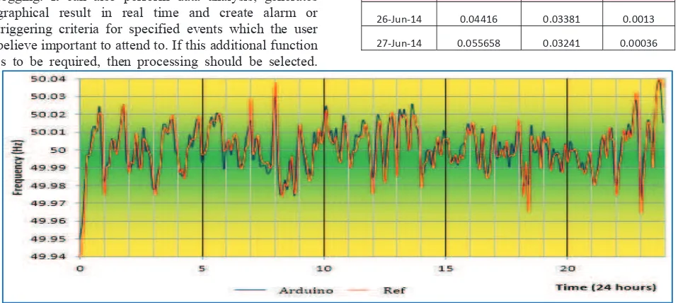
The signal source is obtained from the power outlet is the most appropriate test signal for Arduino frequency measurement device not only because it is within the frequency range standard, but also the frequency changes continuously every single cycle. The frequency changes due to imbalance between generation and demand at the network grid. To prove that the data is accurate and reliable, a reference measurement device is setup simultaneously. Any power quality meter which have the capability of measuring the signal frequency with high accuracy and tolerance is qualified to perform as the reference device. Figure 4 and 5 show the frequency data comparison between Arduino measurement device and the reference device taken on 26th July 2014 and 27th July respectively. Both graph indicates that the measurement device built using Arduino technology performed almost exactly as the reference data. The maximum, minimum and average error of this graph are shown in Table 3.
TABLE 3 Error (Point To Point Differences Between Two Measurement Devices)
Date Maximum (%) Minimum (%)
Average Error (%)
26-Jun-14 0.04416 0.03381 0.0013
27-Jun-14 0.055658 0.03241 0.00036
Fig. 5 Scatter Plot of Arduino data (blue) and Refe
VII. QUALITY & RELIABILI DEVICE
A. Quality And Reliability Standard
Most industrial product provide bounded guarantee on its quality and r The QnR standard depends on the application. Same goes to me instrumentation product, where if th protect the human lives and property, t be high while if it is used to control the room such as air conditioning system somewhat average. Grid frequency mo categorized as important because it im human utility and business for energy pr these two parties, energy provider has m plate thus having a robust and reliab system is compulsory.
B. Phasor Measurement Unit (PM System in Power Grid Monitoring
In European Continent, the quality electrical energy supplied to the busine consumers is well defined by the a Hence, the energy provider has to spe monitoring system. Phasor Measuremen a commercialized frequency measurem specifically by the main stakeholder company, transmission operation authorized body that monitors the over power system. Most PMU calculat frequency from the phase angle. The a techniques depends on amount of averaging. Basically PMU enables the overall picture of power grid narrowin location. Since it is hardwired commun the problem that occurs in communica is eliminated. The cost of such device USD and rises depending on the area o the number of measurement point.
C. Quality of data logging of Arduino
Arduino measurement device is no PMU since both products target differ When PMU is purchased and instal guaranteed a certain period of suppo
ference data (red) taken on 27th July 2014
ITY OF THE
e warranty and reliability (QnR). e nature of its
asurement and e purpose is to the standard will e condition of the , the standard is onitoring can be mpacts the basic rovider. Between more stake on the bility monitoring
MU) Commercial
and reliability of ess and domestic authorized body. end to install the
nt Unit (PMU) is ment device uses such as power company and rall quality of the
tion derive the accuracy of such
sample set for e user to see the ng down to small nication medium, ation via wireless e is around 20K f monitoring and
ot comparable to rent type of user. led, the user is ort and services
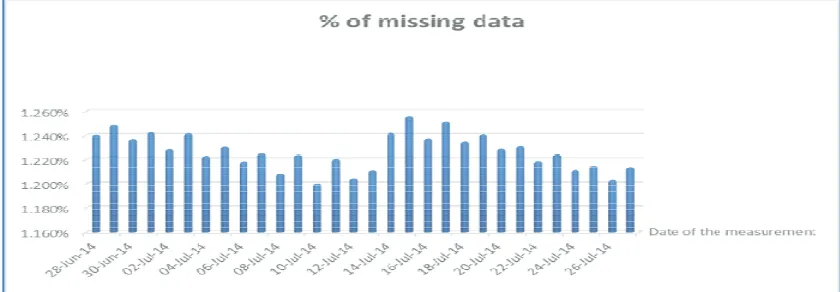
unlike Arduino. The reliability monitoring depends on the p computation increase the r functionality. An experiment performance of Arduino frequ data logging capability over a is shown in Figure 6. In cha program algorithm scrapped s outlier or noise.
This action creates miss for that instance. In terms of because the data logging is no movement small enough to especially TSO’s to make balancing the energy dema frequency regulation guidelin ENTSO-E stated that abno should be tackle within a spe to the degree of the prob monitored so far, the highest movement recorded was 0. where the frequency is hov frequency healthy limit, the T necessary action to stabilize accept data loss when the ave time than the data transfer r missing from a 100 data, the Arduino is acceptable.
VIII. CON
Grid frequency monito energy provider and its releva PMU provides the means to p monitoring task. Monitoring of the grid is also important t to the heavy industrial play portion of the electricity for the monitoring activity al activities in energy transmiss not share the data publicly d Europe for instance, the ener By having the data of deman upper hand to this traders us energy provider over its com energy is not traded and sup managed solely by Tenaga Na
y of Arduino in performing rogram and the chip. Less reliability but effects the
was done to evaluate the uency measurement device a period of time. The result apter IV of this paper, the some data when it contains
sing data at the serial port reliability it is not an issue ot deteriorate but is the data be discarded for the user an important decision in and and supply. The ne handbook published by
rmal frequency deviation ecific time frame according blem. Based on the data
t frequency point to point 005 Hz. In the situation vering near the border of TSO’s should already take the frequency. Even PMU eraging period takes longer rate [7]. With only 1 data e quality and reliability of
NCLUSION
oring is essential to the ant stakeholder. Nowadays perform the grid frequency the quality and reliability to the consumer especially yer because it uses large
small generation plant managers and commercial users to do monitoring while ensures the energy provider adhere to the quality and reliability of its service. With the development cost as low as 100 US Dollar, anyone can own the device and start to monitor the health of our grid. As renewable energy penetration increases such as Photovoltaic (PV) in domestic house, the monitoring activity is much simpler with Arduino measurement device. Keeping tabs on can ensure the PV is working in optimal condition and according to the fit in tariff regulation.
Arduino capabilities is not limited at only frequency measuring. The user can improve the measurement accuracy by adopting other frequency measurement technique such as phasor measurement or Fast Fourier transform which could leads to other parameters being extracted such as signal amplitude and phase angle. The proposed algorithm demonstrated part of Arduino capability and simple method to monitor grid frequency using well known zero-crossing method. The auxiliary circuit is easy to assemble while the program code learning booklet is available online. Arduino in general has triggered self-learning among engineering community just like [8] on how easy it is to design and develop controller and monitoring device with Arduino board and its IDE.
As for the conclusion, the author believes that the data measured by Arduino has negligible error considering that the purpose of the data is to study the behavior of the grid frequency and not for automation or control which require higher specification. Even for the European Network of Transmission System Operators for Electricity (ENTSO-E) standard, the accuracy of the frequency measurement for primary reserve control should be below 10 mHz. In terms of reliability, this device has been tested to run for 30 days non-stop and showing no sign of degradation in its data.
ACKNOWLEDGEMENT
The authors appreciate the support granted by Universiti Teknikal Malaysia Melaka (UTeM) in pursuing this research. Many thanks to Prof. Mike Zehner and Professor Martin Neumaier from the University of Applied Science Rosenheim for the guidance and supervision as well as for providing necessary resources especially the venue at D building at the University of Applied Science Rosenheim. Special thanks to Prof. Dr.-Ing. Simon Schramm from University of Applied Science Munich for providing the reference data to validate the Arduino accuracy.
REFERENCES
[1] ENTSO-E, “UCTE Operation Handbook on Load Frequency Control and Performance P1” European Network of Transmission System Operators for Electricity, 2010 [Online]. Available:
https://www.entsoe.eu/publications/system-operations-reports/operation-handbook/
[3] Atmel Cooperation “8 bit AVR microcontroller Application Notes” page 10 Rev. 2559D-AVR-02/06
[4] M. Robbins and H. Evans, Circuit Lab. Massachusetts: Circuit Lab Inc, 2012
[5] Mikmo.dk, 'MikMo', 2011. [Online]. Available: http://mikmo.dk/blog/. [Accessed: 18- Mar- 2015]. [6] C. Reas and B. Fry, Processing. Massachusetts:
Massachusetts Institute of Technology, 2001 [7] K. Martin, 'Synchrophasor Measurements Under
the IEEE Standard C37.118.1-2011 With Amendment C37.118.1a', IEEE Trans. Power Delivery, pp. 1-1, 2015.