KESAN HABA TERHADAP MENDAKAN DALAM RONGGA YANG BEREBEZA BENTUK
(THE EFFECTS OF HEAT FOR CONTAMINANT REMOVAL FROM DIFFERENT SHAPES OF CAVITY)
MOHD NOOR ASRIL BIN SAADUN
RESEARCH VOTE NO: PJP/2012/FKM(9A)/S01084
JABATAN TERMAL BENDALIR FAKULTI KEJURUTERAAN MEKANIKAL UNIVERSITI TEKNIKAL MALAYSIA MELAKA
ACKNOWLEDGEMENT
KESAN HABA TERHADAP MENDAKAN DALAM RONGGA YANG BEREBEZA BENTUK
(Kata kunci: Mendapan, CFD, aliran salur)
Pencemaran yang baru ditemui pada sendi sistem perpaipan besar yang boleh menyebabkan kecacatan kepada produk perindustrian. Satu analisis berkomputer dilakukan untuk mengesahkan masa lampau struktur aliran rongga dengan menggunakan simulasi perisian FLUENT. Penyingkiran pencemaranberkonsepkan hidrodinamik dengan tambahan haba dan eksperimen dilakukan untuk bentuk segi empat tepat, segitiga dan separuh bulat panjang dengan nisbah kedalaman 2:1. Analisis berkomputer dijalankan untuk menganalisis pemindahan haba dan medan aliran di satu saluran di sebelah bawah rongga. Aliran tak mantap digunakan dalam penyelidikan ini untuk menganalisis aliran dan corak pusaran. Proses gerakan bendalir di sebuah lubang dikira melalui satu penyelesaian berangka persamaan Navier Stokes dengan persamaan tenaga untuk aliran laminar. Penyelidikan ini mula dengan penghasilan geometri manakala pencemaran ialah di dalam rongga. Bagi membuang kesemua pencemaran dalam rongga, keperluan hidrodinamik digunakan di dalam simulasi ini. Kesan hidrodinamik itu akan mengalir dari serokan saluran dan membuat pusaran untuk membuang pencemaran dari rongga. Kehangatan permukaan telah diaplikasikan untuk menetukan kadar pemindahan mempengaruhi penegluaran pencemaran dengan lebih tinggi atau sebaliknya.
Penyelidik:
Mohd Noor Asril Bin Saadun (Ketua) Mohamad Shukri Bin Zakaria Muhammad Zaidan Bin Abdul Manaf
Nur Hazwani Binti Mokhtar Mohd Nazmin Bin Maslan
Email: [email protected]
THE EFFECTS OF HEAT FOR CONTAMINANT REMOVAL FROM DIFFERENT SHAPES OF CAVITY
(Keywords: Contaminant removal, CFD, flow channel)
Contaminant that are recently discovered at the joint of large piping system and can caused defect to industrial product. A computational analysis using simulation of FLUENT software of the hydrodynamic contaminant removal with heat effect is executed and experiments are carried out in order to validate the flow structure past rectangular, triangular and semicircular cavity of length-to-depth ratio 2:1. Computational analysis is performed to analyze the heat transfer and flow field in a channel with cavity heated only at the bottom sides. The cavity that needed to test comes with three (3) types that are square, triangle and semicircle. Unsteady flow are using in this research to analyze the flow of streamlines and vortices pattern. The process of fluid dynamic in a cavity is modeled via a numerical solution of the Navier–Stokes equations with the energy equation for laminar flows. This research starts with the geometry creation. Contaminant was inside the cavities. In order to remove all of the cavities, hydrodynamic need to take part in this simulation. The hydrodynamic will flow from the inlet of the channel and make vortices to remove the contaminant from the cavities. The heat was applied at the bottom of the cavities to analyze if there had present of heat, the contaminant removal rate will be higher or vice versa.
Key-researchers:
Mohd Noor Asril Bin Saadun (Principal) Mohamad Shukri Bin Zakaria Muhammad Zaidan Bin Abdul Manaf
Nur Hazwani Binti Mokhtar Mohd Nazmin Bin Maslan
Email: [email protected]
TABLE OF CONTENTS
ACKNOWLEDGEMENT ... ii
TABLE OF CONTENTS ... v
LIST OF TABLES ... vii
LIST OF FIGURES ... viii
Chapter 1 ... 1
1.1 Introduction ... 1
1.2 Objective ... 2
1.3 Scope ... 3
Chapter 2 ... 4
2.1 Introduction ... 4
Chapter 3 ... 5
3.1 Introduction ... 5
3.3 Mathematical Modeling ... 8
Chapter 4 ... 12
4.1 Experiment ... 12
4.1.2 Data Analysis ... 14
4.2 Simulation ... 17
Chapter 5 ... 20
ACHIEVEMENT ... 21
Name of articles ... 21
Title of paper presentations (local) ... 21
Human capital development ... 21
REFERENCES ... 22
LIST OF TABLES
Table 3:1 Part Description 5
LIST OF FIGURES
Figure 3:1 Geometry for the cavity and flow channel 6
Figure 3:2 Experiment setup 7
Figure 3:3 Different side of heated 11
Figure 4:1 Rectangular Cavity 13
Figure 4:2 Semicircle cavity 13
Figure 4:3 Triangular Cavity 14
CHAPTER 1
1.1 Introduction
the process was the piping system is being flush by greater water pressure by using water jet with the present of removal material such as sodium and more. By this process, the greater impact of pressure will slightly remove the present of contaminants in piping system. From the other term, in different usage of piping system such as piping system in cold area, the usage of cavities with thermal heater is very important in order to prevent the flow of fluids from stuck or freeze. Besides plays a main role in preventing flow from stuck, the present of cavities in piping system also can be used as the medium in process of contaminants removal as well. In the term of fluids dynamic, flow past an open cavity is known to give rise to self-sustained oscillations in a wide variety of configurations and these cavity oscillations are the origin of coherent and broad band sources of noise and if the flow is sufficiently flexible, flow induced vibration as well. Due to this research the main indicator is to determine the rate of contaminants removal for different shapes of cavities. Three shapes of cavity were prepared, semi-circle, triangular and rectangle with respective dimension. The influence of cavity shape on the flow structure within and immediate neighborhood of the cavity is the focal point of this paper as well. The behavior of fluid mechanism such as contour of stream wise, components of velocity, average vortices, Reynolds stress, streamline plots, intensity values are the important parameter for this research. The application of Particle Image Velocimetry (PIV) was used as the medium to analyze the behavior of flow measurement over different shape of cavities.
1.2 Objective
The objective for this research is:
1. To investigate the flow structure over different shapes of cavity of rectangular, triangular and semicircular with heat addition.
1.3 Scope
The scopes of this research are:
1. To study the influence of cavity shape on the flow structure within and immediate neighborhood of the cavity in analysis.
CHAPTER 2
2.1 Introduction
CHAPTER 3
3.1 Introduction
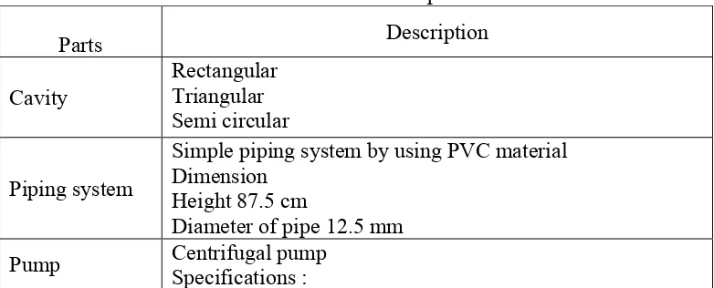
To study the flow characteristic of water with seeding particle along the different shapes of cavities, the proper and complete experimental apparatus need to be set up in order to get the effective result. In this experiment, the water should be flow in fully direction from input of cavity until the output of the cavities, thus the tank were used to provide the sufficient water. Besides that, the pump were used to provide greater fluid flow in this water channel and also to determine the suitable low Reynolds number flow of the water. In order to prevent the seeding particle to enter the pump after being remove from the cavity, the systematic filter were design inside the tank to filter out the seeding particle from enter the pump. The frame of this system was designed from the steel to support the weight of the cavity with a specific dimension relatively related to the specification of PIV instruments as well. Below are the specifications of the full experimental design for this experiment:
Table 3:1 Part Description
Parts Description
Cavity Rectangular Triangular Semi circular
Piping system
Simple piping system by using PVC material Dimension
Height 87.5 cm
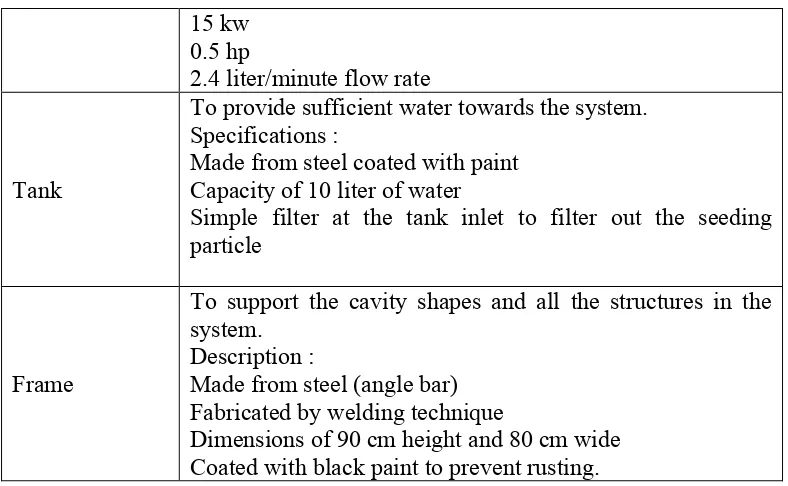
15 kw 0.5 hp
2.4 liter/minute flow rate
Tank
To provide sufficient water towards the system. Specifications :
Made from steel coated with paint Capacity of 10 liter of water
Simple filter at the tank inlet to filter out the seeding particle
Frame
To support the cavity shapes and all the structures in the system.
Description :
Made from steel (angle bar) Fabricated by welding technique
Dimensions of 90 cm height and 80 cm wide Coated with black paint to prevent rusting.
3.2 Design
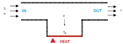
Diagram below show the suggested cavity shape for this analysis.
Figure 3:2 Experiment setup
In this research there are several steps need to be followed to get the good result. The procedure for this experiment is:
a) Set up the orientation of camera, lighting and cavity. b) Fill up the cavity with water and seeding particle. c) Turn on the apparatus and also water pump.
d) Control the valve to get the specific Reynolds number flow by using Flow Meter device. e) For flow imaging experiment, as the water fill the cavity start inject the liquid powder
constantly in the cavity.
f) For particle rate removal, as the water fill the cavity start analyze the removal rate of the cavity with stopwatch.
g) Take the image of the cavity by using CDU device with respective frame per second. h) Record the flow process within a specific time.
3.3 Mathematical Modeling
Vibrations Navier-Stokes equation is a compulsory equation in fluid dynamic fields. The equation is usually apply to the fluid dynamic modeling and this equation usually considered as incompressible. Most fluids flow application was using this equation because in explained the conservation of mass, momentum, and energy the equation almost perfect. In addition, there is no analytical solution to this equation as there are too many Partial Difference Equation (PDE) term in the equation. Now, the research for methodology were wrote down, the equation still not solved by all people in the world. Many type of numerical method were tried out by scientist and engineer, but all of them failed. This equation is unsolvable. It cannot be solved but can be simplified. The dimensionalised governing equations of the fluid flow are given respectively by the equation:
Continuity
(1)
where the mass doesn't changing in value for the steady flow.
Momentum
x direction
y direction
(3)
where u and v are the velocity components in the x and y directions respectively, p is the pressure, ρ is the constant density, and is the iscosity. Using the dimensionless definitions,
(4)
the governing equation (1) to (3) become
(5)
Momentum
x direction
(6)
y direction
Note that equation of (6) and (7) are determined the force act by the flow. In this project, 2D fluid flow being subjected to the convective effect caused by heated wall which stated at the y-component.
Energy Equation
(8)
and use the following non-dimensional forms of the temperature and dissipation function
(9)
and this lead to
(10)
where Re= ; Pr= ; Ra= Are Reynolds number, Prandtl number and Rayleigh number respectively. Dimensional quantity from the defined geometry and assumption made previously then being substituted into these equations for a non-dimensional parameter. From this mathematica mode ing, the re ation of parameters can be shown c ear y and it’s important to define every properties involved in problem statement in order to ensure that solver making all of the consideration.
CHAPTER 4
4.1 Experiment
In flow measurement experiment, the focal point of this study is to determine the rate of contaminant removal for each cavity shapes with constant flow of water with high Reynolds numbers flow and the flow pattern within the cavity with low Reynolds number flow. The rate of contaminant removal was observed by a several aspect. The usage of Particle Imaging Technique provides the measurement of the whole flow field in qualitative manner. The present of contours of constant averaged stream wise and transverse components of velocity, contours of constant averaged vortices, Reynolds stress and streamline plots for each cavity type. In addition, stream wise velocity, Reynolds stress is compared for all cavity types. Effect of cavity shapes on flow structure within the cavity is discussed in details.
In this experiment, generally discussing about two main results which are:
i. Flow pattern for low and high Reynolds number in each cavity. ii. Particle rate removal for high Reynolds number in each cavity.
Rate of Particle Removal for Rectangular Cavity
comparison between two images will represent the rate of particle being removed. The images were divided into grid cube with 28 grid width and 16 grid height. From this, the total grid is about 448 grids. The indicator lines were stated to initiate the initial condition. After 20 seconds the quantity of particle were calculated from the indicator line as well. To calculate the percentage of particle being removed, the grid is assumed in three different condition which is full, half and quarter. Thus , to get the amount of particle being removed, the particle left after 20 seconds is calculated respect to the condition.
Figure 4:1 Rectangular Cavity
Figure 4:3 Triangular Cavity
4.1.2 Data Analysis
In this experiment, technique of qualitative analysis was used. Thus the behavior of the fluid particle along the cavity with respective flow of Reynolds number were observed and here are two types of Reynolds number being used which is low Reynolds number (Re<4000) and high Reynolds number (Re>4500). For determination of flow particle within the cavity for every shape, using the powder liquid which is in white color to determine the flow within the cavity. The liquid powder had been injected along the channel the as the flow enter the cavity area, the image were snap and recorded.
Flow Pattern Analysis
final data analysis. From this method the differences between each cavity fluid flow with respect of fluid flow which is can be differentiate either High or Low Reynolds numbers.
Particle Removal Rate
In this analysis the rate of the seeding particle being removed will be determined with respective of time within each cavity. The High Reynolds numbers of flow were used to get the differences between each cavity. The images were snap from initial (0 seconds) and final (20 seconds). As the image being determined, the image is being divided into grid system about 448 grids for all shapes. To define the rate of particle being removed by calculating the percentage of seeding particle being remove after 20 seconds. The calculative data will represent the rate of removal. By this method, the ability of each cavity to remove the particle inside its will be determined.
Formation of Vortices structures within cavities
Pattern of Streamlines
In this experiment, there are two types of Reynolds number flow being implemented thus it’s gi e the ar iation of resu t from one to another within the ca i ty shapes. The most common differences when the Reynolds number flow is change is the streamlines flow within the cavity. As the Reynolds number increase the rate of fluid entrainment near the upstream cavity wall into the shear layer and forming the single focus. This clearly shown that as the Reynolds numbers increase the formation of a vortex is become more effective and bigger as well. In fluid mechanics terms, this phenomenon is called as dominant vortex.
In Rectangular cavity for small Reynolds numbers flow, the vortex more localized towards the trailing edge of the cavity and become expands and occupy the whole cavity as the Reynolds numbers flow is high. In Triangular cavity shape, the formation of vortex is near to upper right of the cavities in low Reynolds flow and becomes almost to the upper right as in the high Reynolds numbers flow. However in semi-circle cavity the vortex are formed much more near to the upper right of the cavity as the Reynolds number increase. From this, the outcome of the analysis is the increases of the Reynolds number flow resulted the formation of the vortex either is asymmetric or skewed structure within the cavity.
Vorticity Contours