ROBOTIC ARM CONTROLLER DESIGN FOR CAPTURING THE SEQUENTIAL IMAGES SURROUNDING THE OBJECT
TEE WEI SEN
This Report is Submitted in Partial Fulfilment of Requirements for the Bachelor Degree of Electronic Engineering (Industrial Electronic)
Fakulti Kejuruteraan Elektronik dan Kejuruteraan Komputer Universiti Teknikal Malaysia Melaka
UNIVERSTI TEKNIKAL MALAYSIA MELAKA
FAKULTI KEJURUTERAAN ELEKTRONIK DAN KEJURUTERAAN KOMPUTER BORANG PENGESAHAN STATUS LAPORAN
PROJEK SARJANA MUDA II
Tajuk Projek : ………
………
Sesi Pengajian :
Saya ……….. (HURUF BESAR)
mengaku membenarkan Laporan Projek Sarjana Muda ini disimpan di Perpustakaan dengan syarat-syarat kegunaan seperti berikut:
1. Laporan adalah hakmilik Universiti Teknikal Malaysia Melaka.
2. Perpustakaan dibenarkan membuat salinan untuk tujuan pengajian sahaja.
3. Perpustakaan dibenarkan membuat salinan laporan ini sebagai bahan pertukaran antara institusi pengajian tinggi.
4. Sila tandakan ( √ ) :
SULIT* *(Mengandungi maklumat yang berdarjah keselamatan atau kepentingan Malaysia seperti yang termaktub di dalam AKTA RAHSIA RASMI 1972)
TERHAD** **(Mengandungi maklumat terhad yang telah ditentukan oleh organisasi/badan di mana penyelidikan dijalankan)
TIDAK TERHAD
Disahkan oleh:
__ ________________________ ___________________________________
(TANDATANGAN PENULIS) (COP DAN TANDATANGAN PENYELIA)
Tarikh: ……….. Tarikh: ………..
Robotic arm controller design for capturing the sequential images surrounding the object
TEE WEI SEN
iii
“I hereby declare that the work in this project is my own except for summaries and quotations which have been duly acknowledge.”
Signature : ...
Author : ...
iv
“I acknowledge that I have read this report and in my opinion this report is sufficient in term of scope and quality for the award of Bachelor of Electronic Engineering (Industrial Electronics/ Computer Engineering/ Electronic Telecommunication/ Wireless Communication)* with Honours.”
Signature : ...
Supervisor’s Name : ...
v
TABLE OF CONTENTS
CHAPTER CONTENTS PAGE NUMBER
ACKNOWLEDGEMENT VIII
ABSTRACT IX
LIST OF FIGURE X
LIST OF TABLES XII
I INTRODUCTION
PROJECT INTRODUCTION 1
PROBLEM STATEMENT 3
OBJECTIVES 3
SCOPE OF WORK 4
EXPECTED OUTCOME 4
II LITERATURE REVIEW
REVIEW OF THE ROBOTIC ARM DEVELOPMENT BASED
ON SERVO MOTOR 5
2.1.1 RRR JOINT ROBOTIC ARM 5
2.1.2 ROBOTIC ARM DESIGN USING SERVO MOTOR 7
2.1.3 SERVO MOTOR 7
2.1.4 CONCEPT OF THE DC SERVO MOTOR CONTROL 8
vi
3D RECONSTRUCTION 10
2.3.1 MULTIPLE OBJECT SCENES 10
2.3.2 TURNTABLE 3D RECONSTRUCTION 11
2.3.3 RADON TRANSFORM IN IMAGE PROCESSING 11
2.3.4 VOLUMETRIC METHODS 12
2.3.5 PHOTOMETRIC STEREO 13
2.3.6 SHAPE FROM SILHOUETTE 13
2.3.7 SPACE CARVING 15
III METHODOLOGY
PROCEDURE 16
3.1.1 FLOW CHART: 17
HARDWARE: 18
3.2.1 BLOCK DIAGRAM: 18
IMAGE ACQUISITION 20
3.3.1 DESIGN OVERVIEW: 20
3.3.2 CAMERA CALIBRATION 21
3.3.3 SPACE CARVING 22
3.3.4 CONVERSION OF RGB IMAGE TO SILHOUETTE
IMAGES 25
IV RESULT & DISCUSSION
HARDWARE OF CAPTURE PLATFORM: 27
4.1.1 ANALYSIS OF ROTATION FOR SERVO MOTOR IN
vii
4.1.2 ANALYSIS OF THE CAMERA PROJECTION AT
TWO DIFFERENT ANGLE: 32
4.1.3 ANALYSIS OF 3D MODEL AT TWO DIFFERENT
NUMBER OF SEQUENTIAL IMAGES: 43
DISCUSSION: 49
V CONCLUSION & FUTURE WORK
CONCLUSION: 51
FUTURE WORK: 51
REFERENCE 52
viii
ACKNOWLEDGEMENT
ix
ABSTRACT
A development of imaging platform for sequential images were carried out to reconstruct the 3D model. Low cost of automated imaging platform is created by using G15 servo motor with Arduino UNO microcontroller. Two sets of sequential images were obtained using different projection angle of camera. The analysis were carried out by using the space carving reconstruction method based on two different number of sequential images. The accuracy of the 3D models which are generated from different sets of sequential images are compared with the original object. A study based on the conversion of RGB images to silhouette images were carried out in this project. Other than that, an analysis based on the effect of different number in sequential images to the accuracy of 3D model reconstruction also were carried out with the fixed projection angle of camera.
x
LIST OF FIGURE
Figure 1.1.1: Project subsystem ... 2
Figure 2.1.1: Structure of revolute joint ... 6
Figure 2.1.2: Series manipulator ... 6
Figure 2.1.3: Haptic robotic arm ... 7
Figure 2.1.4 Input pulse of the servo motor ... 8
Figure 2.1.5: Corresponding between direction and pulse of servo motor ... 9
Figure 2.2.1: Top view of Arduino Uno board ... 10
Figure 2.3.1: Turntable platform ... 11
Figure 2.3.2: Schematic diagram with one DSLR and four LED ... 13
Figure 2.3.3: Process of the subdivision for each level of occupied voxels ... 14
Figure 2.3.4: Six principles direction in a plane for a scene ... 15
Figure 3.1.1: Flow chart of overall process... 18
Figure 3.2.1: System Design ... 18
Figure 3.3.1: Layout Design ... 20
Figure 3.3.2: Designed Imaging Platform ... 21
Figure 3.3.3: Calibration with checkerboard... 21
Figure 3.3.4: Calibration of checkerboard by using GUI ... 22
Figure 3.3.5: Calibration Process ... 22
Figure 3.3.6: Process of SpaceCarving ... 23
Figure 3.3.7: Sequential Image ... 23
Figure 3.3.8: Voxels carving process ... 24
Figure 3.3.9: 3D Model Result ... 24
Figure 3.3.10: RGB Colour Value ... 25
Figure 3.3.11: RGB images to Silhouette ... 26
Figure 3.3.12: RGB images, HSV images and Silhouette ... 26
Figure 4.1.1: G15 Servo Motor with ID ... 27
Figure 4.1.2: Rotation Analysis ... 28
Figure 4.1.4: Corresponding of Position Value versus Rotation Angle (radian) ... 32
Figure 4.1.5: Hardware Design with Specification ... 33
xi
Figure 4.1.7: Extrinsic Parameter of Calibration Result for Sample 1 (Centred View)
... 34
Figure 4.1.8: Reprojection Error in Sample 1 ... 34
Figure 4.1.9: Overall Calibration Result in Sample 1 ... 35
Figure 4.1.10: 72 sequential image at 22.9 degree projection angle ... 36
Figure 4.1.11: Voxel Carving for first image in Sample 1 ... 36
Figure 4.1.12: Voxel Carving for 22th image in Sample 1 ... 36
Figure 4.1.13: Voxel Carving for 46th image in Sample 1 ... 37
Figure 4.1.14: Voxel Carving for last image in Sample 1 ... 37
Figure 4.1.15: Final 3D model in Sample 1 ... 37
Figure 4.1.16: Second Hardware Design with Specification ... 38
Figure 4.1.17: Extrinsic Parameter of Calibration Result for Sample 2 ... 38
Figure 4.1.18: Extrinsic Parameter of Calibration Result for Sample 2 (Centred View) ... 39
Figure 4.1.19: Reprojection Error in Sample 2 ... 39
Figure 4.1.20: Overall Calibration Result in Sample 2 ... 40
Figure 4.1.21: 72 sequential image at 32.15 degree projection angle ... 40
Figure 4.1.22: Voxel Carving for first image in Sample 2 ... 41
Figure 4.1.23: Voxel Carving for 22th image in Sample 2 ... 41
Figure 4.1.24: Voxel Carving for 42th image in Sample 2 ... 42
Figure 4.1.25: Voxel Carving for last image in Sample 2 ... 42
Figure 4.1.26: Final 3D model in Sample 2 ... 43
Figure 4.1.27: 72 sequential images at fixed projection angle ... 43
Figure 4.1.28: Voxel Carving for first image at fixed projection angle in Sample 1. 44 Figure 4.1.29: Voxel Carving for 24th image at fixed projection angle in Sample 1 44 Figure 4.1.30: Voxel Carving for 42th image at fixed projection angle in Sample 1 45 Figure 4.1.31: Voxel Carving for last image at fixed projection angle in Sample 1 . 45 Figure 4.1.32: Final 3D Model Result for 72 images ... 46
Figure 4.1.33: 36 sequential images ... 46
Figure 4.1.34: Voxel Carving for 5th image at fixed projection angle in Sample 2 .. 47
xii
LIST OF TABLES
Table 1.4-1: Summary of Specification ... 4
Table 3.2-1: Materials of the hardware setup... 19
Table 3.2-2: Specification of G15 Servo Motor... 19
Table 4.1-1: Calculated angle and Measurement Angle with the Position Value ... 28
Table 4.2-1: Summary of analysis in different projection angle ... 50
1
CHAPTER 1
INTRODUCTION
The introduction of thesis has been described in this chapter. It consists of five section which are project introduction, problem statement, objectives, scope of work and expected outcome. In project introduction, details of the project have been stated clearly and summarized. The problem that have been faced by previous study is identified. Besides that, project objectives are listed out accordingly for the achievement of aim of this study. Lastly, scope of work is stated as a guidance in the project and the expected outcome is aimed at the end of this chapter.
PROJECT INTRODUCTION
Nowadays, 3D become more universal dimension in present of perspective effect in our daily life. A lot of propose method have been presented in previous study. One of the 3D reconstruction method is using stacking of 2D image which is capturing by the robotic arm camera. Robot is a manmade mechanism which is used to replace the human work and it is a very useful and efficiency tools.
Traditionally, an object on the turntable is rotated together to capture the sequential image in which the camera is placed in static position. Due to the only one projection view of camera, the limitation in 3D reconstruction have been presented causing the improperly formed of 3D image. In order to overcome this type of limitation, the previous concept is improved by designing an autonomous robotic arm with attach of camera that able to capture the sequential of image surrounding the static object from various angles.
2
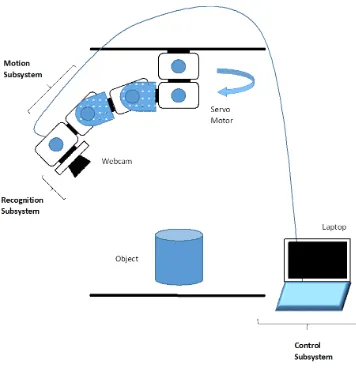
which can rotate through radial axis to capture the surrounding image of the object. The physical structure of the project include capture platform, robotic arm, camera, Arduino microcontroller and G15 shield. Arduino UNO with the G15 shield as a microcontroller of the robotic arm to calibrate the camera for all possible different angle. C++ program is utilized as the interface programing of robotic arm and computer. In the project, it consists of three subsystems which are motion, recognition and control. Figure 1.1.1 show the combination of three subsystems. In motion subsystem, five servo motors are used to form a RRR robotic arm which able to provide a flexible rotation motion. In recognition subsystem, an external webcam is used to capture the object and transfer the image data to Matlab via USB connection. Lastly, Matlab and Arduino IDE are used as the control software path to control overall system.
3
PROBLEM STATEMENT
Three-dimensional (3D) reconstruction is a process to build the 3D image by capturing the surface shape of real object. In our daily life, is hard to create the 3D image with the low cost yet reliable and operate efficiently. A simple method in 3D reconstruction based on 2D image by using the camera calibration will be constructed
[5]. Digital camera is moving at different angle surrounding the object to obtain the
sequential image. However, the invisible part of the camera view cause the problem of less accuracy in highly concave object image reconstruction. Other than that, the limitation of perspective effect due to the parallel geometry beam which make the lower precision in 3D image reconstruction during photographic process [3,5]. In the
beginning, this project is more focus on the simple imaging mechanism setup. Other external work on 3D reconstruction and detailed adjustments will be carry on.
OBJECTIVES
The aim of this project is to develop the 3D imaging system form sequential images surrounding the object. Below objectives have been set to achieve that:
To design the imaging mechanism/device with a camera attach to the robotic arm.
To calibrate the camera for all possible different angle.
4
SCOPE OF WORK
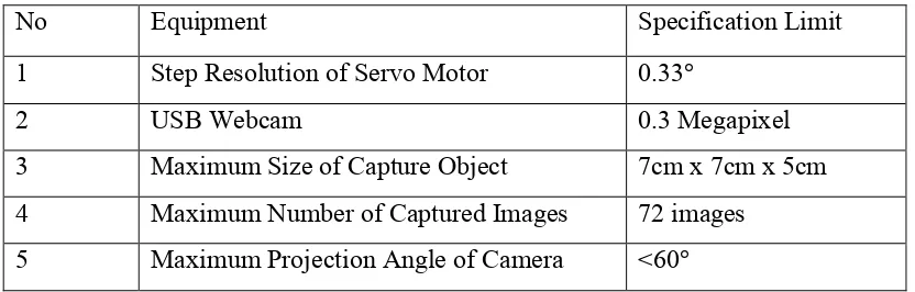
The calibration of camera is restricted according to the precision. The optimization of this can be done if the calibration of each servo motor is accurate with matched coding in Matlab. Arduino UNO with G15 shield is used as microcontroller of those servo motors. The position of robotic arm (Servo Motors) can be set by using C++ programming which is communicate with computer over Universal Series Bus(USB). The image processing process can be performed by applying the Digital Signal Processing (DSP) knowledge in Matlab. The body of the frame can be constructed with the Perspex platform. The capturing platform is able to capture the regular size of the object. Low cost webcam with maximum 640 X 480 resolution will be used as the capture device in the project.
Table 1.4-1: Summary of Specification
No Equipment Specification Limit
1 Step Resolution of Servo Motor 0.33°
2 USB Webcam 0.3 Megapixel
3 Maximum Size of Capture Object 7cm x 7cm x 5cm
4 Maximum Number of Captured Images 72 images 5 Maximum Projection Angle of Camera <60°
EXPECTED OUTCOME
5
CHAPTER 2
LITERATURE REVIEW
This chapter comprise of the previous research that had been done and discussed. It consists of two part which are hardware and software study. A lot of related theory in the project will be discussed in this chapter. It is a guidance through the project and lead the success to the project.
REVIEW OF THE ROBOTIC ARM DEVELOPMENT BASED ON SERVO MOTOR
In 1920, Karel Capek was introduced the first term in robot. At the early stage, robot defined as mechanical devices that operates with autonomy and under computer controlled. According to Robot Institute America (RIA), robot define as reprogrammable multifunctional manipulator which is designed to move material, parts, or specialized devices through variable programmed motion. Based on the journal that was published on June 2000, a simple robotic arm was develop by using servo motor. [13,14] There are two type of control method in robot design which are
servo and non-servo robot. Closed loop computer control in servo robot are used to determine the motion and capable for multifunctional, reprogrammable devices. Non servo robot is using open loop device whose movement is limited to predetermined mechanical stops, and useful for material transfer.
2.1.1 RRR joint Robotic arm
6
Figure 2.1.1: Structure of revolute joint [13]
According to the previous study that published by Ahmet MUTLU [1], a
research assistant at Hacettepe University. A simple way to develop a robotic arm by using servo motor is serial manipulator development. Joint and rigid links are constructed in series with one path leading from the base to the end effector. Large workspace, simple and cheap are the main advantage of this mechanism. However, it have the limitation with sloppy control and movement and lower rigidity. Figure 2.1.2 show the structure of series manipulator with revolute joint.
7
2.1.2 Robotic arm design using servo motor
In the previous study, a lot of method have been proposed in the robotic arm control system. A simple way to design the robotic arm which can pick up the object is using a freedom servo motor [10]. A method which is called Haptic Technology is
presented in the paper to design the robotic arm. Microcontroller (ATMEGA-328) is used as the hardware interface platform to control the motion of robotic arm [13].
Potentiometer is fitted with the remote in the design. Electric pulse is produced by remote motion of the potentiometer. Servo motor will receive the digital pulse after the signal is converted by the arduino board. In this paper, the robotic arm that capable to handle the medium weight of the object is implemented.
Figure 2.1.3: Haptic robotic arm [13]
2.1.3 Servo motor
DC servo motor is an important device which is widely used in many applications. In robotic application, servo motor normally has priority to use in moving
8
the robotic arm to a relevant position in the application which require high-speed control accuracy and high performance dynamic respond [8]. Servo motor is able to
produce the standard magnetic flux with the low inertia of armature due to the low weight design structure. The common problem that are faced during the servo motor controlling is the specific speed and position tuning parameter. One of the solution that is implemented to solve the issues is Fuzzy logic [8, 12]. Currently, there are several
latest interfacing hardware including application-specific integrated circuit (ASIC), advanced RISC machine (ARM), digital signal processing (DSP) and field programmable gate array (FPGA) are available in current market. A lot research have been investigated by the researcher based on the servo system simulation [13].
2.1.4 Concept of the DC servo motor control
Based on the designation, pulse of the variable width is the parameter to control the servo motor. Figure 2.1.4 show the minimum, maximum pulse and repetition rate of the input pulse signal to control the servo motor. According to the theoretical study, the same value of potential rotation in anticlockwise direction and clockwise direction is called neutral position [8]. The rotation angle of the servo motor is determine by the
duration that applied to the signal wire which is called Pulse Width Modulation (PWM). The large the length of pulse, the large the motor turn. Besides that, the position of pulse is repeated to instruct to the servo motor in order to make the static position [11].
9
Generally, the minimum and maximum width of pulse are used to control the servo to turn to a specific position for each servo. The minimum pulse will be about 0.5 ms wide and the maximum pulse will be 2.5 ms wide for the normal servo motor. Some more, the range of duty cycles that the servo motor operate is around 5-10%. Figure 2.1.5 shows corresponding between direction and pulse of servo motor.
Figure 2.1.5: Corresponding between direction and pulse of servo motor [8]
MICROCONTROLLER
Arduino Uno is a common microcontroller that is used to control the robotic arm nowadays. In this project, Arduino Uno have been choose as the microcontroller of the servo motor due to its major advantages compare to the others. Arduino Uno is design based on the ATMega-328 chip which is simple to use with the female pin socket connected to the I/O pin [4]. Other than that, it is self-sufficient which can
10
Figure 2.2.1: Top view of Arduino Uno board
3D RECONSTRUCTION
2.3.1 Multiple Object Scenes
From the previous section, the art of image in the current state is based on reconstruction which is focused on single object. A fixed camera and independently moving the object is concerned to extract 3D information from multiple object. The lies of autonomous and surveillance application as the aim of this invented system. It caused the problem in photorealistic modelling.
The statement of no difference between a scene with single object and several object appear in high level standard have been argued among the researcher. There are the issue on distinction between the real object and reconstruction object are artificial. In previous chapter, algorithms of the single object reconstruction that presented are compact in shape and presented in uncluttered background in order to distinguish from the object of interest. A way to reduce the depth hull of a scene that contain multiple object is the invention of multiple depth maps [5]. A complete method for 3D scene
11
the other one, a multiple scenes is represented in form of individual image layers at various depths.
2.3.2 Turntable 3D Reconstruction
Turntable is a basic method to construct the 3D image instead of using the complex method. Turntable system is used as the sequence image capturing platform. A large number of the view point and calibration step are needed to obtain the image in different angle [15]. Figure 2.3.1 show the basic structure of the turntable 3D
reconstruction. A camera is fixed at the fixed point and single axis of turntable is used as the object capturing platform [6]. However, the limitation exists as the fixed camera
cannot be adjust manually to capture the image in various angle.
Figure 2.3.1: Turntable platform [15]
2.3.3 Radon Transform in image processing
Other than that, a simple 3D reconstruction method by using radon transform algorithm and edge detection are presented [3].A linear transform which is used for
image analysis based on image projection in 3D image reconstruction is called Radon transform. The density profiles of the object scanned that can obtain in different angle
Fixed Camera
12
in projection which is X-ray image are used to analyse compare to other form of image. Internal structure of image can be reconstruct throughout this method. In this method, radon transform algorithm is applied to the image for 2D projection of the object with sonogram generation in slice by slice. Inverse radon transform (IRT) also important in radon imaging, medical imaging and geophysical imaging. Filtered Back Projection (FBP) is a method to obtain the sinogram image reconstruction which is obtained from radon transform (RT) in IRT [9]. Two phase of FBP which are projection and filtration
is presented in previous study. Sinogram is generated to reconstruct projection of the object according slice by slice by using IRT algorithm. Forming the projection of the sinogram result related to its slice is depending to the FBP algorithm. In order to minimize the noise present as low as possible, filtering act as important role in this process.
For edge detection, edge is presented when the pixel intensities of an image under an process of abrupt change. A strong visual clues for image is related to its role in image processing. Further processing such as recognition, image segmentation and line detection can be apply by using technique. Throughout this propose method, a 3D image of the object is obtained by using the low equipment and simple reconstruction method. Time consumption for the process is satisfied and the perspective effect of the image result is acceptable at the end of this research.
2.3.4 Volumetric Methods
The way to estimate the volume of space that occupied by the object is an existing method in computer vision. Mean of the geometric formulation is used as the algorithm in this method. A set of conic is forming by the back projection from the camera position to the silhouette of each image. A lot of different shape can be consistent provide the visual hull, detailed analysis of the minimal hull is presented in previous study [2]. In the study, a method to distinguish between hard point and soft
![Figure 2.1.1: Structure of revolute joint [13]](https://thumb-ap.123doks.com/thumbv2/123dok/474459.51913/18.595.191.485.439.698/figure-structure-of-revolute-joint.webp)
![Figure 2.1.3: Haptic robotic arm [13]](https://thumb-ap.123doks.com/thumbv2/123dok/474459.51913/19.595.137.568.338.610/figure-haptic-robotic-arm.webp)
![Figure 2.1.4 Input pulse of the servo motor [8]](https://thumb-ap.123doks.com/thumbv2/123dok/474459.51913/20.595.175.461.557.685/figure-input-pulse-servo-motor.webp)
