i
THE DESIGN OF A TORQUE FEEDBACK CONTROLLER FOR AN UPPER LIMB ROBOTIC ARM
VIVEK S/O REGEEV
A report submitted in partial fulfillment of the requirement for the Bachelor Degree of Mechatronics Engineering
Faculty of Electrical Engineering Universiti Teknikal Malaysia Melaka
ii
I hereby declare that this report entitle “The design of a torque feedback controller for an upper limb robotic arm” is the result of my own research except as cited in the references. The report has not been accepted for any degree and is not concurrently submitted in candidature of any other degree.
Signature :
Author Name :
iii
“ I hereby declare that I have read through this report entitle “The design of a torque feedback controller for an upper limb robotic arm” and found that it has comply the partial fulfillment for awarding the degree of Bachelor of Mechatronics Engineering with Honours.”
Signature :
Supervisor’s Name :
iv
ACKNOWLEGDEMENT
v
ABSTRACT
vi
ABSTRAK
ix
2.7 Block diagram of the impedance controller with model feed forward 11
x
3.16 Open loop torque model used for system identification 29
4.1 Comparison between the reference input and the output of the system 33
4.2 Speed, output speed and error of uncompensated closed loop speed system. 34
4.3 Speed response graph of closed loop uncompensated speed model 35
4.4 Graph of speed, error and voltage of compensated closed loop speed system. 36
4.5 Speed response of closed loop fuzzy logic compensated system 37
4.6 Speed, error and voltage of fuzzy integral compensated closed loop speed system. 38
4.7 Speed response of closed loop fuzzy integral compensated system 39
4.8 Graph of torque against time (open loop) 41
4.9 Graph of reference torque, output torque and error against time. 42
4.10 Graph of torque against time. 42
4.11 Reference torque, output torque, error and voltage of compensated torque system. 43
6.1 Open loop functional diagram 48
6.2 Open loop speed model 48
6.3 Open loop torque model 49
6.4 Closed loop functional block diagram 50
xi
LIST OF TABLES
NO TOPIC PAGES
3.1 Rule base for the fuzzy logic controller 21
3.2 Motor pins and functions 25
3.3 Microbox ports and description 25
3.4 Mass of robotic arm 31
4.1 Speed model transfer function results 32
4.2 Torque model transfer function results 40
4.3 Comparison of transient response and steady state error of closed
xii
LIST OF APPENDICES
1
CHAPTER 1
INTRODUCTION
1.1 Motivation
Robotic limbs have undergone drastic changes since they were introduced in the early 20th
century. These limbs are now designed so accurately that can resemble that of a human’s. However the control of these arms still poses a problem. In the case of real indoor environments, known obstacles and unknown obstacles change their location dynamically. Moreover, the object shape, speed and position can also alter in an unpredictable way, leading to obstruction of the planned robot motion.[13] The motivation is to improve the control of the robotic arm using torque control, instead of using positioning control alone, torque control allows the controller to calculate the amount of force being exerted on the arm using sensors and using this data to calculate the amount of torque required to counter it in a sense giving the robot tactile sensation to feel the surrounding and make decisions.
2
1.2 Problem statement
3
1.3
Objective
1. To design a suitable controller that is able to control the output torque of an upper limb robotic arm.
2. To test the ability of the controller to control the output speed of an upper limb robotic arm.
1.4
Project Scope
1. To model and develop an upper limb robotic arm
2. To design a torque and speed feedback controller for an upper limb robotic arm based on characteristics obtained during open loop simulation:
a) Speed control
Settling time less than 1 second Steady state error of less than 5%
b) Torque control
4
CHAPTER 2
LITREATURE REVIEW
2.1 Introduction
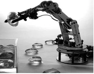
The design of torque controller for an upper limb robotic arm involves the modeling of the controller as well as the hardware. Over the course of decades human beings have been restless in their attempt to seek replacements that would be able to mimic their behavior as seen in Figure 2.1.
Figure 2.1: Example of SCARA robotic limbs modeled after humans
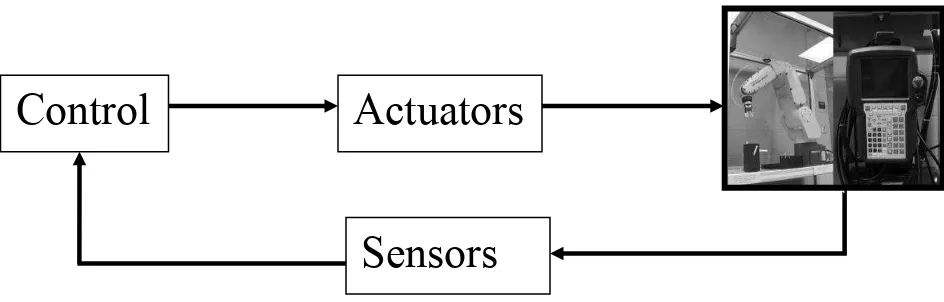
5 Figure 2.2: Robotic System Components
However, robotics would be a redundant field if not for the application of a control system in their design. A control system has the capability to connect action to perception in a highly intelligent fashion which is needed to follow through the execution of the action with respects to the goal set.
Control
Actuators
6
2.2 Robot arm
The robotic arm is the part of the robot where the end effectors and sensors are normally located for them to do their pre-programmed business [3].Robot arm is usually used to pick up and place. Figure 2.3 displays a 6 joint robot arm using a motion controller that is able to control up to two axes and 5 degree of freedom robot arm. This robot is normally used at laboratory for training or research purposes. The movement resembles human joints. This robot will move according the programming and coordinate system, axis-y and axis-x [4]. Job of robot arm include:
1. Rotating body towards object 2. Moving gripper down to object 3. Use gripper to picking object
4. Pick up the object and avoiding obstacles 5. make a rotating object towards final objects 6. Put object down
7. Lifting the object
8. Lifting arm to home position 9. Rotating body to home position
7
2.3 DC motor
The electric motor utilizes electrical energy and converts it to mechanical energy or force. The theory of converting electrical energy into mechanical energy by electromagnetic means was first founded by the British researcher Michael Faraday and comprised of a free hanging wire dropped into a pool of mercury. A permanent magnet was then in the middle of the mercury pool. Once current is supplied to the wire, the wire rotates around the magnet giving rise to a circular magnetic field. [5]
Electric motor can be separated into two types Direct Current (DC) and Alternating Current (AC). Modern electronic control has taken great strides in the past couple of decades; modern drivers have been able to remove the commutator out of the motor shell. For this new type of motor, driver circuits are relied upon to produce the sinusoidal Ac drive momentums. An example of this type of motor is the brushless Dc motor which is a polyphone Ac motor needing external electronic control. [6]
A synchronous motor and asynchronous motor have a very obvious difference. The synchronous motor works by oscillating the field or current going through the motor which in turn causes the rotor to rotate in sync. Conversely, an asynchronous motor is required to slip in order to rotate properly.
Most DC motor design produces an oscillating current in a wound rotor using a split ring commutator or permanent magnet stator. A rotor comprises of a coil wound around a rotor which is then controlled by a battery. There are three main types of DC motor which is the stepper motor, brushed DC motor and brushless DC motor.
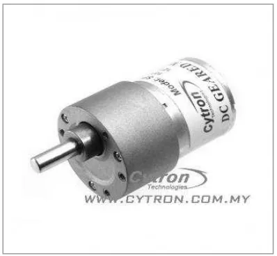
Actuation of a robotic arm normally has a certain set of requirement: 1) High torque
8 A brushless DC (BLDC) motor makes a good the actuator due to its ability to produce high torque at low speed. Figure 2.4 displays a BLDC motor with a gear mechanism that increases the rated torque that the motor can produce. Besides that, other benefits of this motor is that it doesn’t need a complex power supply, doesn’t heat up quick and has a big torque to size ratio.
9
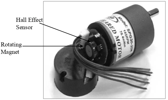
2.4 Hall effect sensor
Hall Effect sensor is a transducer commonly used for positioning, current sensing and speed detection applications. It works by varying its output voltage as a response to a provided magnetic field. In a DC motor a Hall Effect sensor functions to time the speed of the motor shaft.
Figure 2.5: Hall Effect sensor attached to a DC motor
10
2.5 Control system
Many conventional approaches have been discussed in the literature to the control of various robotic limbs, including that of the robust control method [7]. Approaches such as these generally require mathematical modeling for the design of the controller, an approximate one at least. Artificial intelligence methods, mainly neural networks and fuzzy logic design, in recent years have also been proposed. Using artificial intelligence methods a precise system model usually isn’t required in the design of a controller. Heidar A. Malki et. al. [7] proposed the method of using fuzzy logic integrated with PID control in controlling a flexible joint robotic arm. Through experimental results seen in figure 2.6 it was seen that the performance of the fuzzy logic PID controller had improved the tracking performance and was more robust when compared to a conventional PID controller [8].
Figure 2.6: Conventional PID performance (L) vs. fuzzy PID performance(R) [7]
12
2.6 Fuzzy logic controller
![Figure 2.7: Block diagram of the impedance controller with model feed forward [2]](https://thumb-ap.123doks.com/thumbv2/123dok/552832.65037/23.612.107.513.89.274/figure-block-diagram-impedance-controller-model-feed-forward.webp)
