CONTINUOUS MAPPING OF TUNNEL WALLS IN A GNSS-DENIED ENVIRONMENT
Michael A. Chapman a , Cao Min b andDeijin Zhang b
a
Department of Civil Engineering, Ryerson University, Toronto, Canada [email protected] b
Zoyon Science and Technology Co.., Wuhan, China [email protected]
Commission VI, WG VI/4
KEY WORDS: Tunnel mapping, image mosaicking, image bridging, visual odometry, GNSS-denied
ABSTRACT:
The need for reliable systems for capturing precise detail in tunnels has increased as the number of tunnels (e.g., for cars and trucks, trains, subways, mining and other infrastructure) has increased and the age of these structures and, subsequent, deterioration has introduced structural degradations and eventual failures. Due to the hostile environments encountered in tunnels, mobile mapping systems are plagued with various problems such as loss of GNSS signals, drift of inertial measurements systems, low lighting conditions, dust and poor surface textures for feature identification and extraction. A tunnel mapping system using alternate sensors and algorithms that can deliver precise coordinates and feature attributes from surfaces along the entire tunnel path is presented. This system employs image bridging or visual odometry to estimate precise sensor positions and orientations. The fundamental concept is the use of image sequences to geometrically extend the control information in the absence of absolute positioning data sources. This is a non-trivial problem due to changes in scale, perceived resolution, image contrast and lack of salient features. The sensors employed include forward-looking high resolution digital frame cameras coupled with auxiliary light sources. In addition, a high frequency lidar system and a thermal imager are included to offer three dimensional point clouds of the tunnel walls along with thermal images for moisture detection. The mobile mapping system is equipped with an array of 16 cameras and light sources to capture the tunnel walls. Continuous images are produced using a semi-automated mosaicking process. Results of preliminary experimentation are presented to demonstrate the effectiveness of the system for the generation of seamless precise tunnel maps.
Introduction
This paper focuses on the estimation of reliable three dimensional coordinates, geometric forms and non-spatial attributes of features in harsh environments such as tunnels. The need for reliable systems for capturing precise detail in tunnels has increased as the number of tunnels (e.g., for cars and trucks, trains, subways, mining and other infrastructure) has increased and the age of these structures and, subsequent, deterioration has introduced structural degradations and eventual failures (Gordon and Lichti, 2007, Hashimoto et al, 2006, Ioannidis et al, 2006, Masoto et, 2007 and 2008, Monserrat and Crosetto, 2008, Stiros and Kontogianni ,2009, Tsakiri et al, 2006). Due to the hostile environments encountered in tunnels, mobile mapping systems are plagued with various problems such as loss of GNSS signals, drift of inertial measurements systems, low lighting conditions, dust and poor surface textures for feature identification and extraction. This research was aimed at the use of alternate sensors and algorithms which will are used to develop a reliable mapping system that can deliver precise coordinates and feature attributes from surfaces along the entire tunnel path. Various grades of inertial measurement units (IMU) have been introduced to assist the positioning and orientation process especially when there are outages of the GNNS signals. Recently, lower cost systems in the form of micro electro-mechanical systems (MEMS) have been employed to bridge the gap between cost and the delivery of reliable orientation information. While these small form factor IMUs have found application in various scenarios, they suffer from various sensitivities such as high drift rates, vulnerability to temperature changes and susceptibility to low grade electrical, magnetic and mechanical loadings. Other sensors include compasses, distance measurement instruments (DMI), lasers and range cameras. Each of these sensor types suffers from various shortcomings when used for positioning and orientation estimation (Abellan et al, 2009 and 2011, Buckley et al, 2008, Burton et al, 2010, Dekker et al, 2008, Fekete et all, 2010 and 2012).
Research Outline
Expanding upon previous work undertaken by the author’s
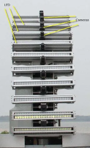
research group, the possibility of using image-based solutions in the presence of artificial lighting offers a new opportunity to solve the mapping problem in situations of extended GNSS outages such as in tunnels. This process was termed image bridging and is also known as visual odometry. The fundamental concept is the use of image sequences to geometrically extend the control information in the absence of absolute positioning data sources. Previous work has been carried out using geodetic and photogrammetric techniques although there were limitations to the success (Kim et al, 2008, Kontagianni and Stiros, 2003, Otoo et al, 2011, Sciaioni et al, 2014, Yamaguchi and Hashimoto, 2010). The image sequences are processed to determine candidates for matching. This is a non-trivial problem due to changes in scale, perceived resolution, image contrast and lack of salient features. Originally, these image bridging techniques suffered from high computational requirements and limited computing power. Current processing capabilities have virtually overcome such problems. The sensors to be employed will include forward looking high resolution digital frame cameras coupled with auxiliary light sources. In addition, a high frequency lidar system (Shan and Toth, 2008) and a thermal imager will be included to offer three dimensional point clouds and thermal images of the tunnel walls, respectively. The mobile mapping system to be used is already equipped with an array of cameras and light sources to capture the tunnel walls (see Figure 1a and 1b).
Figure 1a Lateral View of Camera and Reflector Array
Figure 1b Close-up of cameras and strobe lights
Forward-looking cameras are employed for capturing the longitudinal direction ahead of the tunnel mapping system.The forward looking cameras are calibrated to account for geometric distortions, radiometric irregularities and to define relative orientation parameters in the case of camera pairs (see Table 1).
Table 1 Sensor Specifications
In addition, the lever arms and boresighting angles related to the tunnel wall cameras, lidar system and thermal imager are calibrated using well-established methodologies (Cosandier and Chapman, 1995). The radiometrically processed images are
filtered to extract image matching candidates based upon algorithms such as the modified Forstner Interest Operator (Forstner and Gulch, 1987). Using relative image relationships, geometric constraints in terms of epipolar geometry are used to restrict the search space for image feature matching. This operation can be used initially for image pairs and, then, for image sequences as the successive image geometry is progressively defined. A modified form of the Levenberg-Marquadt algorithm is employed to control variations in image geometry and to dampen the effect of parameters that are particularly non-linear and contribute to divergent solutions when using least squares estimation. Additional geometric constraints can be introduced with inclusion of highway geometry conditions that are specific to transportation corridors. These constraints can attenuate the variations of the image-based solution. A bundle adjustment solution is used to process the image sequence to ensure consistency of the image acquired along the vehicle path. This is an extension of work previously carried out by this research group (Chaplan and Chapman, 2001). An extended Kalman filter is employed such that the image estimated position and orientation information can be used along with the DMI data to produce updated estimates for the mobile mapping platform at time (t). In addition, digital inclinometer data associated with the tunnel wall cameras will be employed as observables to assist in the estimation of the roll angles. Weighted constraints are applied to exploit the well-defined vehicle motion characteristics such as restricted range of role and pitch angles as well as the change in vertical vehicle position for example. In the case where there are loop closures, additional constraints can be applied to reflect the reacquisition of the GNSS signal or the return to a common set of points when multiple vehicle runs in the same or opposite directions are available. In parallel, the images sets from tunnel wall cameras will be processed to form mosiacked strips representing the walls of the tunnel. The current camera configuration consists of sixteen cameras (see Figure 2) pointed at fixed angles looking to the left or right (user selectable) in one pass.
Figure 2 Close-up of Camera and Reflector Array
In an operational mode, the LED strobe light bank is synchronized with the camera shutters to maximize illumination when travelling within the tunnel. A specialized arched Sensor # Details Characteristics
Camera (Lateral)
16 1920 x 1080 pixels
Visual Band
LED 34 100W Stroboscopic
DMI 1 0.19 m /
km
Calibrated
Camera 1 640 x
480 pixels
Thermal IR
Camera (Forward)
1/2 1920 x 1080 pixels
Visual Band
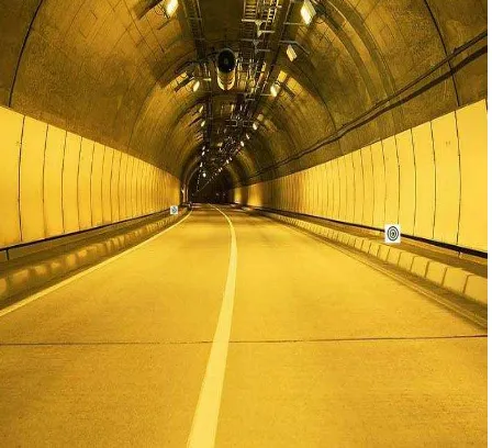
calibration field permits the focusing and calibration of the individual cameras using a resolution test pattern. Camera focal settings are locked once optimal focus is achieved. The introduction of the LED light bank was deemed essential due to the low lighting conditions encountered in the tunnel environments (see Figure 3).
Figure 3 Operational mode of Mobile Tunnel Mapper
Since the mapping system is designed for tunnel, the problem of loss of precise position and orientation must be overcome. Control targets and features are introduced and precisely mapped to offer a set of ground-truthing points which are used to verify the location and nature of features detected on the tunnel walls. Such forms of verification are essential for validating the various algorithms for positioning and image mosaicking. The targets introduced in the tunnel corridor are viewable from both directions and can be measured in the images from the forward looking cameras. The targets are designed with concentric circles so that they can be precisely measured at various sighting distances (see Figure 4). The introduction of these targets offers a means to overcome the loss of precise position information when in GNSS-denied environments such as tunnels using image bridging.
Figure 4 Artificial Targets along Tunnel Corridor
Camera capture events are also synchronized with the travel velocity of the mobile platform so that there is overlap between
successive swaths of imagery. The overlap between the images swaths will be used to create geometrically and radiometrically correct mosaics. The individual swaths will then be connected to successive swaths using the overlap between the image sequences. In addition, the time-stamped derived positional data will used to ensure that scale is preserved along the image continuum collected along the vehicle path.
Figure 5 Mosaicked Image Profiles
Test Results
Preliminary results were generated using a 980 m two lane tunnel configuration. Three scenarios are evaluated: 1) no forward camera use, 2) a single forward-looking camera and 3) a stereo pair of forward-looking cameras. All solution incorporated a forward-reverse data collection assumption since the tunnel mapping system currently requires two passes to completely cover the tunnel wall surface. A total of 52 images / image pairs where employed for the evaluation.
An extended bundle adjustment with constraints was used to estimate the extrinsic parameters of the images acquired by the forward-looking cameras. In the case of absence of a solution using forward-looking imagery, the position and orientation of the mapping vehicle are determined with RMS errors of 1.21m, 0.87 and 0.39m in Easting, Northing and elevation, respectively. With the incorporation of a refined solution using a single forward-looking camera, the RMS errors were 0.14m, 0.12m and 0.08m in Easting, Northing and elevation, respectively. An improvement in the solution was achieved when using stereo pairs of images from forward-looking cameras. In this case, the RMS errors were 0.11m, 0.09m and 0.06m in Easting, Northing and elevation, respectively (see Figure 6). The RMS errors for the heading were 2.1 deg, 45 arc sec and 58 arc sec., respectively.
Table 2 Preliminary Results: Positioning and Orientation Orientation None Double Single
Parameter RMS RMS RMS
Easting (E) 1.21 m 0.11 m 0.14 m
Northing (N) 0.87 m 0.09 m 0.12 m
Elevation (h) 0.39 m 0.06 m 0.08 m
RMS heading 2.1 deg. 45 arc sec 58 arc sec
Conclusions and Recommendations
A tunnel mapping system has been developed with the capability of precisely mapping tunnel walls in poor lighting environments with the absence of GNSS-derived data within the tunnel corridor. With the incorporation of artificial targets and various geometric constraints, precise position and orientation parameters are obtained. As such, surface cracks and other effects of deterioration can be identified and localized using the image sequences obtained from the lateral camera array. It is envisaged that improved results can be realized when additional points are identified in the images from the forward-looking cameras. These additional points would enhance the position and orientation estimates from bundle adjustment. Improvements in the image processing are underway to enhance the radiometric and geometric quality of the image mosaics from the sequential image swaths.
References
Abellan, A., Jaboyedoff, M., Oppikofer, T., Vilaplana, J.M. (2009) Detection of millimetric deformation using a terrestrial laser scanner: experiment and application to a rockfall event. Natl Hazards Earth Syst Sci 9 (2), 365–372.
Abellan, A., Vilaplana, J.M., Calvet, J., Garcia-Selles, D., Asensio, E., 2011. Rockfall monitoring by terrestrial laser scanning – case study of the basaltic rock face at Castellfollit de la Roca (Catalonia, Spain). Natl Hazards Earth Syst Sci 11 (3), 829–841.
Chaplan, B.A. and Chapman, M.A. (2001) Collection of Roadway Asset Data along an Obstructed Urban Corridor, 3rd International Sysmposium on Mobile Mapping Technology, Cairo, Egypt, January, S2-3, (CD-ROM), 5p.
Cosandier, D. and Chapman, M.A. (1995) Precise
Multispectral Airborne Pushbroom Image Georectification and DEM Generation, Proceedings of ISPRS/IAG/FIG Workshop on Integrated Sensors Orientation, Barcelona, September, 4 - 8, pp. 91-100.
Decker, J.B., Dove, J.E. (2008) Laser scanning techniques in
Devil’s Slide tunnels. In: Laser and Photogrammetric Methods
for Rock Tunnel Characterization Workshop. Tononm, F. (Ed.). 42nd US Rock Mechanics Symposium, San Francisco.
Fekete, S., Diederichs, M., Lato, M. (2010) Geotechnical and operational applications for 3-dimensional laser scanning in drill and blast tunnels. Tunn. Undergr. Space Technol. 25 (5), 614–628.
Fitzgibbon, A.W., Pilu, M., Fisher, R.B. (1996) Direct least squares fitting of ellipses. In: The 13th International Conference on Pattern Recognition, Los Alamitos, CA, USA.
Forstner, W. and Gulch, E. (1987) A Fast Operator for Detection and Precise Location of Distict Point, Corners and Centres of Circular Features", Proceedings of the ISPRS Conference on Fast Processing of Photogrammetric Data. Interlaken, pp. 281-305.
Gabriel Walton, Danielle Delaloye, Mark S. Diederichs (2014) Development of an elliptical fitting algorithm to improve change detection capabilities with applications for deformation monitoring in circular tunnels and shafts, Tunnelling and Underground Space Technology, Volume 43, July 2014, Pages 336–349.
Gigli, G., Casagli, N. (2011) Semi-automatic extraction of rock mass structural data from high resolution LIDAR point clouds. Int. J. Rock Mech. Min. Sci. 48 (2), 187– 198.
Gordon, S.J., Lichti, D.D., 2007) Modelling terrestrial laser scanner data for precise structural deformation measurement. J. Surveying Eng. 133 (2), 72–80.
Hashimoto, T., Koyama, Y., Yingyonggrattanakul, N., Kayukawa, K., Konda, T., Sugimoto, M. (2006) Applications of the new deformation meter for monitoring tunnel lining deformation. In: The International Symposium on Underground Excavation and Tunnelling, Bangkok, Thailand.
Ioannidis, C., Valani, A., Georgopolous, A., Tsiligiris, E. 2006. 3D model generation for deformation analysis using laser scanning data of a cooling tower. In: The 3rd IAG Symposium on Geodesy for Geotechnical and Structural Engineering and 12th FIG Symposium on Deformation Measurement, Baden, Austria.
Kim, K.Y., Kim, C.Y., Lee, S.D. (2008) Measurement of tunnel 3-D displacement using digital photogrammetry. World Tunnel Congress 2008. India. pp. 735–742.
Kontagianni, V., Stiros, S. (2003) Tunnel monitoring during the excavation phase: 3-D kinematic analysis based on geodetic data. In: 11th FIG Symposium on Deformation Measurements, Santorini, Greece.
Lato, M., Diederichs, M.S., Hutchinson, D.J., Harrap, R. (2009) Optimization of LiDAR scanning and processing for automated structural evaluation of discontinuities in rockmasses. Int. J. Rock Mech. Min. Sci. 46 (1), 194–199.
Lindenberg, R., Uchanski, L., Bucksch, A., Van Gosliga, R. (2009) Structural monitoring of tunnels using terrestrial laser scanning. Rep. Geodesy 2 (87), 231–239.
Masato, Udai (2008) A Method of Automated Correction of Tunnel Wall Image and Detection of Tunnel Wall Deformation, Technical Paper, Railway Technical Research Institute, 185-8540, Tokyo, Japan.
Masato, U., Nozomi, N. (2007) A High-performance Inspection System of Tunnel Wall Deformation Using Continuous Scan Image, Quarterly Report, Vol. 48, No. 2 P 94-98, Railway Technical Research Institute, 185-8540, Tokyo, Japan.
Masato, Ukai (2007 ) Advanced Inspection System of Tunnel Wall Deformation using Image Processing, Quarterly Report, Vol. 48 (2007) No. 2, Railway Technical Research Institute, 185-8540, Tokyo, Japan.
Monserrat, O., Crosetto, M. (2008) Deformation measurement using terrestrial laser scanning data and least squares 3D surface matching. ISPRS J. Photogr. Remote Sens. 63 (1), 142–154.
Nguyen, H.T., Fernandez-Steeger, T.M., Wiatr, T., Rodrigues, D., Azzam, R. (2011) Use of terrestrial laser scanning for engineering geological applications on volcanic rock slopes – an example from Madeira island (Portugal). Natl. Hazards Earth Syst. Sci. 11 (3), 807–817.
Nuttens, T., De Wulf, A., Bral, L., De Wit, B., Carlier, L., De Ryck, M., et al. (2010) High resolution terrestrial laser scanning for tunnel deformation measurements. In: The FIG Congress 2010 Facing the Challenges – Building the Capacity.
Otoo, J.N., Maerz, N.H., Duan, Y., Xiaoling, L. (2011) Lidar and optical imaging for 3-D fracture orientations. In: 2011 NSF Engineering Research and Innovation Conference, Atlanta, Georgia.
Poropat, G.V. (2006) Remote 3D mapping of rock mass structure. In: The Laser and Photogrammetric Methods for Rock Face Characterization.
Ray, A., Srivastava, D.C. (2008) Non-linear least squares ellipse fitting using the genetic algorithm with applications to strain analysis. J. Struct. Geol. 30 (12), 1593–1602.
Sciaioni, M., Barazzetti, L., Guissani, A., Prrevitali, M., Roncoroni, F. (2014) Photogrammetry Techniques for Monitoring Tunnel Deformation, Earth Science Informatics, Volume 7, Issue 2, pp 83-95
Shan, J., Toth, C.K. (2008) Topographic laser ranging and scanning: principles and processing. CRC Press, 1–590.
Slob, S., Hack, H.R.G.K., Feng, Q., Roshoff, K., Turner, A.K. (2007) Fracture mapping using 3D laser scanning techniques.
In: The 11th Congress of the International Society for Rock Mechanics: The Second Half Century of Rock Mechanics, Lisbon, Portugal.
Stiros, S., Kontogianni, V. (2009) Mean deformation tensor and mean deformation ellipse of an excavated tunnel section. Int. J. Rock Mech. Min. Sci. 46 (8), 1306– 1314.
Tesfamariam, E.L. (2007) Comparing discontinuity surface roughness derived from 3D terrestrial laser scan data with traditional field-based methods. Unpublished Dissertation/Thesis, International Institute for Geo-information Science and Earth Observation, The Netherlands.
Tsakiri, M., Lichti, D., Pfifer, N. (2006) Terrestrial laser scanning for deformation monitoring. In: The 3rd IAG Symposium on Geodesy for Geotechnical and Structural Engineering and 12th FIG Symposium on Deformation Measurement, Baden, Austria.
Yamaguchi, T., Hashimoto, S. (2010) Fast crack detection method for large-size concrete surface images using percolation-based image processing, Machine Vision and Applications - Integrated Imaging and Vision Techniques for Industrial Inspection, Volume 21 Issue 5, August, Pages 797-809.