Geo-referenced mapping using an airborne 3D time-of-flight camera
T. K. Kohoutek a, *, M. Nitsche b, H. Eisenbeiss a
a Institute of Geodesy and Photogrammetry, Swiss Federal Institute of Technology ETH, 8093 Zurich, Switzerland -
(tkohoutek, ehenri)@ethz.ch b
Mountain Hydrology and Torrents Unit, WSL Swiss Federal Institute for Forest, Snow and Landscape Research,
Birmensdorf, Switzerland -manuel.nitsche@wsl.ch
KEY WORDS: Range Imaging, UAV, real time, 3D geometric mapping, elevation model
ABSTRACT:
This paper presents the first experience of a close range bird’s eye view photogrammetry with range imaging (RIM) sensors for the real time generation of high resolution geo-referenced 3D surface models. The aim of this study was to develop a mobile, versatile and less costly outdoor survey methodology to measure natural surfaces compared to the terrestrial laser scanning (TLS). Two commercial RIM cameras (SR4000 by MESA Imaging AG and a CamCube 2.0 by PMDTechnologies GmbH) were mounted on a lightweight crane and on an unmanned aerial vehicle (UAV). The field experiments revealed various challenges in real time deployment of the two state-of-the-art RIM systems, e.g. processing of the large data volume. Acquisition strategy and data processing and first measurements are presented. The precision of the measured distances is less than 1 cm for good conditions. However, the measurement precision degraded under the test conditions due to direct sunlight, strong illumination contrasts and helicopter vibrations.
* Corresponding author. Tel. +41 44 633 30 41
1. INTRODUCTION
Measurement of surfaces and their geometrically accurate reconstruction for visualization in three-dimensional models is an important challenge in several geodetic and environmental applications. Detailed topographical measurements are for example essential for many geomorphological research questions. However, particularly in steep mountainous areas it is difficult to measure complex morphologies. Measurements are complicated by vegetation cover, uneven and steep terrain, and difficult accessibility (Nitsche et al. 2010). Airborne Lidar systems or terrestrial laser scanners are difficult to use in those regions because they need line of sight, elevated positions and good aerial or road access. Terrestrial laser scanning (TLS) is a rapid, precise and costly survey technique to measure fluvial topography for example under good conditions (Hodge et al. 2009). However, the fine mechanical scanning devices can make it difficult to use laser scanner under hazardous environmental conditions (Marszalec et al. 1995).
Stereo photogrammetry needs good contrast in a scene to identify features in two images and to measure their displacement. Furthermore, the stability of the ambient light level and spatial distribution of target reflectivity have an impact on the performance of those systems (Sackos et al. 1996).
Range Imaging (RIM) offers a per-pixel distance measurement as well as a grey scaled image of the scene of up to 50 frames per second (f/s). According to the manufacturer, the ranging accuracy of the current model SR4000 is +/-1.5 cm for objects within a distance of 8 m at a level of 99 % reflectivity (MESA Imaging AG 2011).
Nadir view is necessary for many mapping and monitoring applications, e.g. road surface reconstruction (Yu et al. 2007), vegetation monitoring (Rango et al. 2009, Tucker 1979), agricultural surveillance and decision support (Herwitz et al. 2004) and measuring fluvial topography (Nitsche et al. 2010). For the measurement of rough terrain nadir view is often inevitable to minimize or avoid scan shadows behind larger objects like boulders as well as to minimize the amount of scan positions.
In the first experiment, the RIM cameras were mounted on a lightweight camera crane that can lift up to 3.5 kg. The crane had a maximum usable arm length of 4.8 m and offered a top view of up to 4.6 m above the ground (ABC Products 2010). The acquired 3D images of the mounted RIM camera have to be matched by connecting points that have been measured by a total station or global navigation satellite system (GNSS) to be geo-referenced in a global coordinate system.
In the second experiment, a RIM camera was tested on an unmanned aerial vehicle (UAV). An UAV is semi-autonomously or semi-autonomously flying remotely controlled aerial vehicle. The platform can be equipped with a photogrammetric measurement system, including, but not limited to a small or medium size still video or video camera, thermal or infrared camera systems, airborne Lidar system, or a combination of such equipment. Current standard UAVs allow registration and tracking of the position and orientation of the implemented sensors in a local or global coordinate system. Hence, UAV photogrammetry can be understood as a new photogrammetric measurement tool. UAV photogrammetry opens various new applications in the close range domain, combining aerial and terrestrial photogrammetry, but also International Archives of the Photogrammetry, Remote Sensing and Spatial Information Sciences, Volume XXXVIII-5/W12, 2011
introduces new (near-) real time application and low-cost alternatives to the classical manned aerial photogrammetry (Eisenbeiss 2009).
In the presented work the RIM camera CamCube 2.0 was mounted on the unmanned helicopter NEO S-300 by Swiss UAV that can be controlled manually, assisted or completely autonomous and is able to lift up the equipment, including RIM camera, Netbook and batteries of about 5 kg in total.
2. RANGE IMAGING
RIM cameras acquire the distance information of the scene for each individual pixel coded in 16 bit grey values by the time-of-flight (TOF) principle (Lange et al. 2001). The direct output of Cartesian 3D coordinates is possible as well. These solid state constructions contain no moving parts. RIM cameras use an amplitude-modulated continuous light emitter along with a CCD/CMOS receiver. The sensor samples the reflected light regularly and measures the phase shift φ of the modulation with an autocorrelation function (Möller et al. 2005) from which the distance can be calculated. The tested range imaging cameras operate with a wavelength of 850 to 870 nm and a modulated frequency of 25 - 30 MHz. The current array size varies between 64 x 48 and 204 x 204 pixels (Kohoutek 2009).
Several calibration approaches for RIM cameras have been developed to compensate for intrinsic error sources like temperature and lens distortion (e.g. Kahlmann, 2009; Westfeld et al., 2009; Lichti et al., 2010; Böhm and Pattinson, 2010). However, camera calibration is not straightforward and beyond the scope of the present paper. The manufacturing specifications for the tested cameras are shown in Table 1.
Table 1: Specifications of the used RIM cameras (Nitsche et al. 2010)
Model SR4000 CamCube 2.0
Modulation frequency (MHz) 29 - 31 18 - 21 Unambiguous measurement range (m) 0.8 - 5 0.3 - 7.5
Sensor pixels 176 x 148 204 x 204
Field of view (degree) 43.6 x 34.6 40 x 40 Mean resolution at 3 meter (mm) 13.6 10.7 Footprint area at 3 meter (m2) 4.48 4.77
Camera weight (g) 470 1370
Camera dimensions (mm) 65x65x68 180x194x180
Frame rate (f/s) 54 25
Illumination wavelength (nm) 850 870
Price (€) ~5500 ~7500
3. BIRD’S EYE VIEW REALIZATION
3.1 Light weight crane and RIM
For the measurements in an alpine streambed, the RIM camera CamCube 2.0 was mounted on the commercial lightweight camera crane MiniCrane 520 by ABC Products (Figure 1). Larger areas were captured by turning and moving the crane. An overlapping of 30 – 50 % of the camera footprints simplified data assembly during post processing. The integration time of
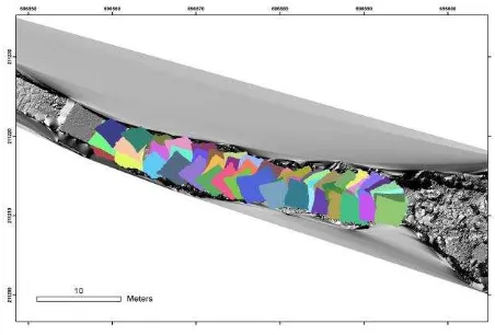
the CamCube camera was 2500 μs. The test area in the streambed of the Erlenbach (Switzerland) has a length of around 40 m and was captured with 60 footprints (Figure 2).
Figure 1 crane with mounted camera over streambed.
The effects of varying ambient light conditions, water and wet rock surfaces on the distance measurement in mountain streambeds have been described by Nitsche et al. 2010. Thereby, the quality of single distance measurements clearly varied with ambient light conditions. While measurements at night revealed greatest details of the surface, the image became obscured at direct sunlight exposure due to a worse signal-to-noise-ration. Noise was reduced and the quality of the distance data was enhanced by averaging of 30 repeated distance measurements. Using a 3 x 3 matrix median filter was effective to remove remaining noise and implausible values (Nitsche et al., in prep.). Accurate measurements on or through water surfaces were difficult to obtain. On flat water surfaces it was possible to penetrate the water up to 5 cm and it would be possible to analyse these data in matters of multimedia photogrammetry (Maas, 1995). However, usually turbulent water scattered the light and led to large variations in the distance measurements.
A total number of 100 reference points have been measured, to merge the footprints and to geo-reference the resulting point cloud (Figure 2). Those reference points were round targets, made of retro-reflective material, with a diameter of 4 cm Three to six reference points have been placed at the edges of each footprint. From the referenced point cloud a digital terrain model (DTM) was generated with standard interpolation techniques (Figure 3). The point density inside the DTM is 2.4 points/cm2.
Figure 2 RIM footprints overlapping a laser scan from the study
site “Erlenbach”.
Figure 3 DTM (shaded relief) of “Erlenbach” generated from range images.
3.2 UAV and RIM
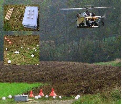
For the first experience with RIM cameras mounted on a UAV system, an open field in the countryside was selected as test area. A prototype of the unmanned helicopter NEO S-300 (Figure 4) system from Swiss UAV was employed as an experimental platform. The NEO S-300 has a maximum take-off weight of 85 kg and a size of 275 x 95 x 86 cm (L x W x H). Its rotor diameter is about 300 cm. Powered by a 12 kW JetA1 single turbine, the NEO can reach a speed of 120 km/h with a flight time of up to 90 minutes and a maximum mission range of about 50 km. With these specifications, the helicopter can fly in the autonomous and assisted flight mode supported by the GPS/INS based autopilot system. The observed GPS coordinates can be used for the georeferencing process of the acquired image data. A payload volume in the helicopters nose can accommodate various camera, laser or radar systems. The hull is divided up into several lids which can be removed. They give access to the modular electronics and mechanical components, allowing easy maintenance and exchange. The outer NEO shell is made of carbon composite materials and acts as the structural component of the helicopter (Swiss UAV 2011).
This NEO prototype operates without a shell and allows the quick attachment and modification of the measurement equipment. In addition to the RIM camera, a 360° prism was mounted on the UAV (Figure 5) to track the helicopter’s position with a total station. The comparison of the onboard generated GPS position with the tachymetry measurements will be analyzed in upcoming works and is not part of this study. During the test, the NEO was steered in the assisted flight mode. For the data acquisition over the test area, the UAV system hovered in three height levels, at 3 m, 5 m and 7 m above the ground, limited by the ambiguity range of the RIM sensors.
To verify the resolution of the RIM camera at different flight heights, a non-geo-referenced test field was created with several objects varying in size, shape and material.
Figure 4 Unmanned helicopter NEO S-300 series.
Figure 5 Experimental NEO platform with CamCube 2.0, 360° prism and standard Netbook.
The smallest objects in the test field were cylinders with a height of 5 cm. Furthermore, spheres of 12 and 15 cm diameter and lumbers, a plastic box and ~40 cm high cones completed the test field (Figure 6).
One of the practical challenges in the experiment was the energy supply for the RIM camera. Several 12 V/2 Ah batteries were mounted on the helicopter to support an operating window of ~10 minutes for the RIM camera. For the first test, a standard Netbook was used for capturing the images. The mechanical hard disk did not properly work during the flight due to the vibrations of the helicopter jet engine. Consequently a Netbook with solid state disk (SSD) was mounted on the helicopter for the data acquisition. Although the SSD was not influenced through the vibration of the UAV system, the processor was not powerful enough to acquire range images with a sufficient frequency. In comparison to the first experiment in the Erlenbach, the images during the UAV test were taken with 4 f/s (frames per second) instead of 16 - 20 f/s. This was solely a result of the slow Netbook processor.
Figure 6 Test field in the countryside and overflying NEO platform (top left: close up of the test objects). International Archives of the Photogrammetry, Remote Sensing and Spatial Information Sciences, Volume XXXVIII-5/W12, 2011
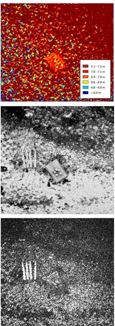
This low frame rate strongly influenced the data processing. As mentioned in chapter 2.1, a single range image is very noisy and data quality has to be enhanced by averaging a number of images of the same footprint. The measurements from the UAV did not yield enough images from one area to calculate an average image for useful noise reduction. However, it was possible to detect the test field objects in a single exposure (Figure 7).
Examining the intensity image already gives an impression on the high noise level. However, the test field objects are clearly visible. In contrast, the median filtered range image shows only the box object clearly. Smaller objects cannot be distinguished from the noise. A better result would be achieved using the intensity image1 and amplitude image2 together to define regions of interest in the range image. For further tests it is necessary to improve robustness and speed of the computer processor and disk for image acquisition.
4. CONCLUSION
In the present paper, the suitability of RIM cameras as aerial image sensors has been presented in two experiments. Experimental tests to evaluate the sensors usability and performance in new outdoor applications have shown reasonable accuracy and precision for a mobile airborne sensor platform. Range imaging cameras can be used as aerial photogrammetry sensors to generate 3D surface models with centimetre resolution. Georeferencing of those models can be done by additional sensors like total stations or GNSS. Hereby, reference points or the position of the imaging platform can be determined. The main advantage of range imaging in comparison to TLS is its light weight and robustness, which enables us to mount the camera on small unmanned aerial vehicles. Furthermore, RIM cameras measure a complete distance image at a time and they capture grey scale images in real time video mode. The camera size, weight and the costs for the sensors are relatively low compared to a laser scanner. However, compared to a stereo camera system the image size is smaller (204 x 204 pixels CamCube 2.0 vs. 1280 x 960 pixels Bumblebee XB3). On the other hand the smaller size is a great advantage with respect to fast data processing and the corresponding point problem from stereo vision does not exist for a still-video RIM camera system.
The first tests with RIM and UAV platforms showed that this combination of sensors is a promising technique for fast 3D data acquisition (e.g. river beds in alpine areas). However, a moving platform adds additional problems to the measurement. Besides helicopter vibrations and power supply, the computer speed for image acquisition was the main limiting factor in our test, which has to be improved for future investigations. In conclusion, the combination of a RIM sensor and an UAV may be used as a fast mapping system under hazardous environmental conditions in future applications.
Acknowledgment
Swiss UAV AG (Niederdorf, Switzerland) maintained and operated the UAV, and cooperated with payload physical and electronic integration onto the airframe.
1 Image of the total signal including ambient light 2
Image of the amplitude of the emitted signal
Figure 7 aerial range image (5 m flight height) top: median filtered single distance image, middle: single
intensity image, bottom: single amplitude image. International Archives of the Photogrammetry, Remote Sensing and Spatial Information Sciences, Volume XXXVIII-5/W12, 2011
References
ABC Products, 2011. „MiniCrane 520”. http://www.abc-products.de/english_09/minicrane520_e_09.html last check in March 2011
Böhm, J. and Pattinson, T., 2010. „Accuracy Of Exterior
Orientation For A Range Camera”, ISPRS Commission V Mid
-Term Symposium: Close Range Image Measurement Techniques, IAPRS XXXVIII Part 5
Eisenbeiss, H., 2009. „UAV photogrammetry“. DISS. ETH NO. 18515, http://e-collection.ethbib.ethz.ch/eserv/eth:498/eth-498-02.pdf#search=%22(author:henri eisenbeiss)%22 last check in March 2011
Herwitz, S.R., Johnson, L.F., Dunagan, S.E., Higgins, R.G., Sullivan, D.V., Zheng, J., Lobitz, B.M., Leung, J.G., Gallmeyer, B.A., Aoyagi, M., Slye, R.E. and Brass, J.A., 2004. „Imaging from an unmanned aerial vehicle: agricultural surveillance and
decision support”. Computers and Electronics in Agriculture.
Vol. 44, 49-61
Hodge, R., Brasington, J. and Richards, K., 2009. „In situ characterization of grain-scale fluvial morphology using Terrestrial Laser Scanning”. Earth Surface Processes and Landforms. Vol. 34 (7), 954-968
Kohoutek, T.K., 2009. „Multi-user vision interface based on
range imaging”. SPIE Defence, Security + Sensing, Visual Information Processing XVIII, Proc. of SPIE Vol. 7341, 73410M · © 2009 SPIE
Lange, R. and Seitz, P., 2001. „Solid-State, Time-of-Flight Range Camera”. IEEE Journal of Quantum Electronics. Vol. 37 (3), 390-397
Lichti, D.D., Kim, C. and Jamtsho, S., 2010. „An integrated bundle adjustment approach to range-camera geometric
self-calibration”. ISPRS Journal of Photogrammetry and Remote Sensing. Vol. 65 (4), 360-368
MESA Imaging AG, 2011. „SR4000 Data Sheet”.
http://www.mesa-imaging.ch/dlm.php?fname=pdf/SR4000_Data_Sheet.pdf last check March 2011
Maas, H.-G., 1995. „New developments in Multimedia
Photogrammetry”. Optical 3-D Measurement Techniques III
(Eds.: A. Grün, H. Kahmen), Wichmann Verlag, Karlsruhe Marzalec, J., Myllylä, R. and Lammasniemi, J., 1995. „A LED-array-based range-imaging sensor for fast three-dimensional shape measurements”. Sensor and Actuators A. Vol. 46-47, 501-505
Möller, T., Kraft, H., Frey, J., Albrecht, M. and Lange, R., 2005. „Robust 3D measurements with PMD sensors”. Proc. of the 1st Range Imaging Research Day at ETH Zurich, Zurich, Switzerland
Nitsche, M., Turowski, J.M., Badoux, A., Pauli, M., Schneider, J., Rickenmann, D., Kohoutek, T.K. 2010. „Measuring
streambed morphology using range imaging“. River Flow 2010
- Dittrich, Koll, Aberle & Geisenhainer (eds) - © 2010 Bundesanstalt für Wasserbau ISBN 978-3-939230-00-7
Nitsche, M., J. M. Turowski, A. Badoux, D. Rickenmann, T. K. Kohoutek, M. Pauli, and J. W. Kirchner, 2011. „Range Imaging: a new method for high-resolution topographic
measurements in the field“. Earth Surface Processes and
Landforms, in prep.
PMDTechnologies GmbH, 2011. http://www.pmdtec.com/ last check July 2011
Point Grey Research, Inc., 2011. „Bumblebee datasheet”, http://www.ptgrey.com/products/bbxb3/bumblebee2_xb3_datas heet.pdf last check July 2011
Rango, A., Laliberte, A., Herrick, J.E., Winters, C., Havstad, K., Steele, C. and Brown, D., 2009. „Unmanned aerial vehicle-based remote sensing for rangeland assessment, monitoring and
management”. Journal of Applied Remote Sensing, Vol. 3
Sackos, J., Bradley, B., Nellums, B. and Diegert, C., 1996. „The
Emerging Versatility of a Scannerless Range imager”. Sandia
National Laboratories
Swiss UAV, 2011. „NEO S-300 series”. http://www.swiss-uav.com/uav_systems.php# last check in March 2011
Tucker, C.J., 1979. „Red and Photographic Infrared Linear
Combinations for Monitoring Vegetation”. Remote Sensing of
Environment. Vol. 8, 127-150
Westfeld, P., Mulsow, C., Schulze, M., 2009.
„Photogrammetric calibration of range imaging sensors using intensity and range information simultaneously”. Optical 3-D Measurement Techniques IX. Vol. II, pp. 129
Yu S.J., Sukumar, S.R., Koschan A.F., Page, D.L. and Abidi, M.A., 2007. „3D reconstruction of road surfaces using an integrated multi-sensory approach”. Optics and Lasers in Engineering. Vol. 45, 808-818