ROBUST PARALLEL MOTION ESTIMATION AND MAPPING WITH STEREO
CAMERAS IN UNDERGROUND INFRASTRUCTURE
Chun Liu, Zhengning Li*, Yuan Zhou
College of Surveying and Geo-Informatics, Tongji University, Shanghai 200092, China -(liuchun, 1210857,zhouyuan)@tongji.edu.cn
Commission I, ICWG I/Va
KEY WORDS: Stereo Visual Odometry, 3D Reconstruction, Parallel Structure, Underground Infrastructure
ABSTRACT:
Presently, we developed a novel robust motion estimation method for localization and mapping in underground infrastructure using a pre-calibrated rigid stereo camera rig. Localization and mapping in underground infrastructure is important to safety. Yet it’s also nontrivial since most underground infrastructures have poor lighting condition and featureless structure. Overcoming these difficulties, we discovered that parallel system is more efficient than the EKF-based SLAM approach since parallel system divides motion estimation and 3D mapping tasks into separate threads, eliminating data-association problem which is quite an issue in SLAM. Moreover, the motion estimation thread takes the advantage of state-of-art robust visual odometry algorithm which is highly functional under low illumination and provides accurate pose information. We designed and built an unmanned vehicle and used the vehicle to collect a dataset in an underground garage. The parallel system was evaluated by the actual dataset. Motion estimation results indicated a relative position error of 0.3%, and 3D mapping results showed a mean position error of 13cm. Off-line process reduced position error to 2cm. Performance evaluation by actual dataset showed that our system is capable of robust motion estimation and accurate 3D mapping in poor illumination and featureless underground environment.
* Corresponding author
1. INTRODUCTION
Modern urban development and expansion has increasingly shifted to underground infrastructures to relieve ground traffic loads. Mapping underground infrastructures becomes an important task for general management and security. Moreover, as these underground infrastructures age, mapping and inspection is becoming more critical to avoid catastrophic failures. However, traditional surveying methods for mapping large-scale underground infrastructure is a time-consuming and challenging endeavour. We developed a novel robust motion estimation method for localization and mapping in underground infrastructure using a pre-calibrated rigid stereo camera rig. Our parallel motion estimation and mapping system is capable of operating in underground environment with poor illumination and without GPS signal. It automatically reconstructs the 3D model of the infrastructure in actual scale.
The predominant practice for 3D mapping of underground infrastructures is the use of tripod-mounted terrestrial laser scanners at a sequence of static stations (Fekte et al, 2010). This mapping method is accurate but consuming in both labour and instrument. On the other hand, mobile mapping solutions, including those based on Simultaneous Localization and Mapping (SLAM), are applied in underground environment. (Robert et al, 2014) developed a solution capable of estimating the motion trajectory of mobile platforms as well as 3D point cloud of the environment. Their system is mainly depending on laser scanner as the primary sensor and has been installed in underground mines. In their algorithm, captured images are only used as texture information of the environment. While others (Peter Hansen et al, 2015) took the advantage of modern camera systems and established a visual mapping system for gas pipe inspection. In their work, they used fisheye imaging to produce
3D textured surface models of inner pipe walls which is of accuracy and practicality. Yet their 3D maps had not absolute scales and were not measurable. In the present paper, we built a parallel structure and transformed the state-of-the-art Visual Odometry (VO) and stereo 3D mapping algorithm to survey underground infrastructures.
The parallel structure set up two separate threads, one deals with motion estimation while the other one deals with 3D mapping. This set up avoids data-association problem in SLAM and is more robust in mapping underground structure. Stereo VO algorithms are known to be accurate and robust (Scaramuzza et al, 2011), and therefore elected as our motion estimation algorithm. Enframing feature matching, pose estimation and non-linear refinement, stereo VO provides accurate motion estimation results for 3D mapping of the environment, and were implemented in several successful above-ground applications (Fraundorfer et al, 2012). Nonetheless, developing a stereo VO solution for underground infrastructure where visual structure and appearance is very different from ground environment remains non-trivial. Specifically, major restrictions introduced by underground infrastructure are poor lighting conditions and featureless artificial structures, which create challenges for feature detection and matching. We developed a modified RANSAC (Fischler et al 1981) scheme to overcome poor matching and produced robust motion estimation results for underground environment. While the motion estimation thread is running, the 3D mapping thread would map all valid pixels to local coordinates instantaneously, and projects them to global coordinates according to the estimated camera motion (Geiger et al 2011).
In the following section (section 2), we presented our parallel mapping system and described methods of motion estimation The International Archives of the Photogrammetry, Remote Sensing and Spatial Information Sciences, Volume XLI-B1, 2016
and mapping for underground infrastructure. Section 3 describes the mobile mapping platform we used for data collection and correspondent calibration method. We performed a set of experiments and demonstrated the results of our parallel system performing in underground infrastructure and highlight the advantage of our system, as elaborated in section 4. Finally, we concluded our work and discussed further improvements in section 5.
2. PARALLEL MOTION ESTIMATION AND MAPPING
2.1 Parallel Structure
The parallel motion estimation and mapping (PMEM) structure was first introduced by (Klein et al, 2007). PMEM employs two separate threads, one for estimating the motion of camera pose through analysing every single frame, and another for mapping the environment by applying bundle adjustment to a set of spatially distributed keyframes. The PMEM is a valid approach of simultaneous localization and mapping (SLAM) in a previously unknown environment. However, PMEM is quite different from common Extended Kalman Filter (EKF) based SLAM approaches, and performs better in underground environment. To our knowledge, the EKF-SLAM is an incremental mapping method: localization and mapping are intimately linked by updating current camera pose and the landmark positions together upon acquisition of every single frame (Durrant-Whyte et al, 2006). We hereby raise our main argument that modeling underground infrastructure is a more difficult task comparing to above-ground scenario. Firstly, underground infrastructure often house featureless artificial structures like plain walls; secondly, with insufficient lighting, the field-of-view (FOV) of camera system is restricted. These restrictions rendered difficulties in reconstructing the surroundings in each frame and caused failure to subsequent mapping associated localization. This data-association problem can irretrievably corrupt the maps generated by incremental systems. PMEM however, does not abide by these restrictions. Since motion estimation and mapping are assigned to separate threads, the former is no longer slaved to the latter, and enables the use of state-of-the-art motion estimation method to ensure robustness in underground scenario.
Currently, consumer-level computers are often packed with multi-core processors, allowing us to split motion estimation and mapping into two different threads. Freed from computational burden of mapping at every frame, the motion estimation thread can process more information in every single image and furtherly improves performance. Moreover, adjacent frames often contain redundant information, particularly when the mobile platform moves slowly. Since mapping is not associated to motion estimation, it is not necessary to use every frame for mapping. Ergo, we select a smaller number of meaningful keyframes for mapping. Detailed motion estimation and mapping algorithms are elaborated in the following section.
2.2 Motion Estimation
When moving through an environment, the stereo camera system takes images at discrete time instants . The main task of motion estimation is to estimate the position and pose of each image in one coordinate system. To attain robustness, we choose the stereo VO algorithm to estimate the motion. Stereo VO computes the relative transformation of two camera positions at adjacent time instants and and then to concatenate the transformations to recover the full trajectory of the cameras. The VO algorithm deals
2) Project the corresponding features from previous frame into 3d coordinates via triangulation using the calibration parameters of the stereo camera rig.
3) Calculate the reprojection into the current image by
( ) ( in featureless underground infrastructure, the wrong matched feature percentage is higher than above-ground cases due to poor illumination and unremarkable features. Employing the standard RANSAC in this situation lead to a wrong convergence when the algorithm starts with groups of wrong matches. We develop a modified RANSAC scheme by initializing RANSAC with long-traced features. Long-traced features (LTF) are matched in several sequence frames. These LTFs have a property of being correct matched and thus retains the integrity after several matches. After RANSAC, all inliers keyframes and map features are added to the system, to extend the map. The added new Keyframes should meet the following conditions:
1) The motion estimation result of the keyframes must be correct.
2) Time interval between two keyframes must exceed certain amout (in our case every five frames).
3) Position interval between two keyframes must be greater than a minimum distance.
Before mapping with the new keyframe, the motion is estimated by VO system and all feature correspondences are established. After initialization, the simplest 3D mapping method maps all valid pixels to local 3D coordinates and projects them to a The International Archives of the Photogrammetry, Remote Sensing and Spatial Information Sciences, Volume XLI-B1, 2016
common coordinate system according to the estimated camera motion. However, as more frames are added while the mobile platform moves, the storage requirements grow rapidly. Further, single feature in reality may relate to several points in 3D maps due to motion estimation error. In our 3D mapping scheme, when a new frame is added, only 3D points that have not been matched in the previous frames will be added. These 3D points of matched features are fused subsequently via computing their 3D mean. This 3D matching scheme not only reduces storage requirements, but also improves 3D mapping accuracy by averaging out stereo measuring noise over several frames. To further improve the 3D mapping accuracy, off-line batch process method such as bundle-adjustment is adopted to reduce mapping error.
3. MOBILE SYSTEM AND CALIBRATION
3.1 Mobile 3D-Mapping System
To collect underground data and for further analyses, we installed sensors, computer hardware and actuators on a prototype mobile platform. Demonstrating in Figure 1, our underground 3D mapping hardware is based on a four-wheel mobile platform (patent pending) which is an unmanned electric vehicle.
Figure 1. The appearance of the mobile mapping system
The vehicle has an external dimension of 1.7m*0.7m*1m, weights 150kg and has an additional payload of 120kg. Driven by an electric motor, the vehicle runs quietly and smoothly and cruising speed can be set at three levels. To compensate for low light condition, two high-intensity LEDs are mounted on the front providing additional illumination. As far as sensor equipment, the prototype has wheel encoders, sonic radar and stereo camera rig consisting of two Canon digital cameras mounted rigidly and is adjusted to parallel optical axis. Two cameras are trigged by the interval signal from the control unit and are synchronized at millisecond level. Exposure time and frequency are configured manually accommodating different scenarios. The mapping system is run by a consumer-level multicore computer. Powered by two sets of lead batteries, the whole system is capable of functioning for 4 hours or 20 kilometres without interrupt.
3.2 Calibration and Rectification
To simplify the calculation process and produce accurate results, we calibrated the stereo camera rig before collecting each of the datasets in section 4. The main objective of calibration is to accurately measure the intrinsic and extrinsic parameters of the stereo camera system. The intrinsic parameters describe the
projection relation of the 3D point in global coordinates and 2D point position in pixel coordinates, while the extrinsic parameters describe the mutual position and orientation between left and right cameras. One of the widely used toolboxes for camera calibration is Bouget’s Matlab Camera Calibration Toolbox, of which a C++ version has been implemented in the OpenCV library. We used the calibration function in OpenCV, which offers automatic corner detection, and built a fully automated calibration program. A set of 20 stereo images of a checkerboard placed at different positions were used as standard inputs for calibration.
After calibration, the relative position between the two cameras is measured and corresponding features can be matched more efficiently and accurately along the epipolar line. In our case when the two cameras are rigidly implemented during the experiment, it’s more efficient to rectify the images according to the calibration parameter than computing the epipolar line for each candidate feature. The stereo rectified image coordinates and are produced by rotating the rays about the camera centers, and then applying a pinhole projection using the left and right camera matrices and .
The and are the normalized pinhole coordinates derived from the intrinsic calibration parameters. The rotation used in the rectification, and rotate the cameras principal axes so that they are orthogonal to the vector joining the camera centers, and the epipolar lines are horizontally aligned.
4. EXPERIMENTS, RESULTS&DISCUSSION
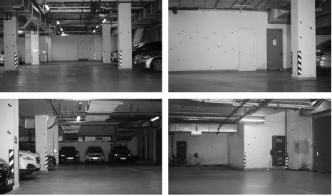
In this section, we collected a data set to evaluate the performance of our parallel system. The experiment data set is collected in an underground garage with limited illumination and featureless artificial structure, which are two main issues in underground modelling. Before we collect the data, the stereo camera rig is calibrated and all images are rectified with the calibration parameter. Sample images collected are shown in figure 2.
Figure 2. Sample images of the collected dataset
The performance of motion estimation algorithm is evaluated by calculating the loop-closure error of the motion trajectory. To evaluate the 3D modelling accuracy, visually salient targets are set on walls and measured by total station. The modelling error are measured by the comparing the targets position from 3D modelling thread with the ground truth acquired from total station.
4.1 Motion Estimation Results
As mentioned in section 2, we kept the track of LTFs to attain robustness of the RANSAC based motion estimation algorithm. Here we defined LTFs as features traced in three consecutive frames. Initializing RANSAC scheme with LTFs performed better in outlier rejection and kept robustness of motion estimation algorithm. The whole trajectory of the experimental data is shown in figure 3.
Figure 3. Loop-close trajectory
The results showed that our algorithm performed without failure in estimating the motion of all image pairs in 66.34 meters. The final closure error is 20.4 cm, the relative error, which is calculated by dividing the closure error by the travelled distance, is 0.3%. According to our previous above-ground experiments with images acquired during 140-meter travelling, the relative error was 0.57%. The underground motion estimation algorithm achieves similar reliability as the above-ground method, which indicates that the negative factors of underground environment are alleviated by our algorithm.
4.2 3D Mapping Results
3D mapping accuracy is evaluated by comparing the control point position in 3D map with total station-measured results. On-line process results are compared with off-line bundle-adjustment (BA) and controlled BA. Since the 3D map and control points have different coordinate systems, some control points are used to calculate the coordinate transformation parameter and no control points are referred in the On-line process and BA. In controlled BA, half control points are used in the processing while others are used to check the position accuracy.
Mean Error RMS
mm mm
On-line process 130.5 122.3
BA 23.42 57.82
Controlled BA 6.322 6.34
Table1. Mean Error and RMS of different method
The on-line process highly depends on the motion estimation results, and the accumulated error in motion estimation decreases the on-line process accuracy. While the off-line BA method minimizes reprojection error of the whole 3D points, it effectively reduces 3D mapping error. However, BA is a time-consuming process, in our case it took 3 hours to produce the final results. Controlled BA takes the advantage of precise position of the control points and therefore further improves mapping accuracy. From the results, On-line process is more suitable for smaller scenario, and large scale scenario necessitates offline process to ensure mapping accuracy.
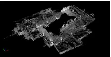
Figure 4 shows illustrated the whole 3D map after BA, the missing part in the middle is the result of difficult acquisition of that area due to parking vehicles and thus are not reconstructed by our mobile mapping system.
Figure 4. Entire 3D map of the underground garage
More details of the 3D map are shown in Figure 5, corresponding actual structures are shown in Figure 2. The featureless structures (mainly plain walls) remain a problem in the 3D mapping process, since the features are not detected and matched in that area. Aside from those structures, the ground and the roof of the garage are correctly reconstructed, this is exceptionally valuable in inspection task in underground.
Figure 5. Detail 3D map of different scenario
5. CONCLUSIONS AND FUTURE WORKS
In this paper we presented a parallel system for underground 3D mapping. The system was evaluated and tested by actual datasets in an underground garage and successfully generated the 3D map. The results indicated that the parallel structure is suitable for localization and mapping in the underground scenario. In the future, we plan to improve the on-line mapping accuracy with loop-closure detection, and validate the algorithm in other underground scenarios.
ACKNOWLEDGMENTS
This work is supported by the International Technical Cooperation Project of Shanghai (Project No: 14530722400). The International Archives of the Photogrammetry, Remote Sensing and Spatial Information Sciences, Volume XLI-B1, 2016
REFERENCES
Fekete, S., et al., 2010. Geotechnical and operational applicati- ons for 3-dimensional laser scanning in drill and blast tunnels. Tunnelling and Underground Space Technology, 25(5), pp. 614-628.
Zlot, R., et al., 2014. Efficient Large scale Three dimensional Mobile Mapping for Underground Mines. Journal of Field Robotics, 31(5), pp.758-779.
Hansen, P., et al., 2015. Visual mapping for natural gas pipe inspection. The International Journal of Robotics Research, 34(4-5), pp.532-558.
Scaramuzza, D., et al., 2011. Visual odometry [tutorial]. IEEE Robotics & Automation Magazine, 18(4), pp.80-92.
Fraundorfer, F., et al., 2012. Visual odometry: Part II: Matching, robustness, optimization, and applications. IEEE Robotics & Automation Magazine, 19(2), pp.78-90.
Fischler, M., et al., 1981. Random sample consensus: a paradi- gm for model fitting with applications to image analysis and automated cartography. Communications of the ACM, 24(6), pp.381-395.
Geiger, A., et al., 2011. Stereoscan: Dense 3d reconstruction in real-time. IEEE Intelligent Vehicles Symposium (IV), pp.963-968
Klein, G., et al., 2007. Parallel tracking and mapping for small AR workspaces. Mixed and Augmented Reality, ISMAR 2007. 6th IEEE and ACM International Symposium, pp.225-234.
Durrant-Whyte, H., et al., 2006. Simultaneous localization and mapping: part I. IEEE Robotics & Automation Magazine, 13(2), pp. 99-110.