ENHANCEMENTS IN UAV FLIGHT CONTROL AND SENSOR ORIENTATION
M. Bäumker a,H.-J. Przybilla a,A. Zurhorst b
a
Bochum University of Applied Sciences, Department of Geodesy, Lennershofstr. 140, 44801 Bochum, Germany – (manfred.baeumker, heinz-juergen.przybilla)@hs-bochum.de
b
aerometrics GmbH & Co. KG, Landwehrstr. 143, 59368 Werne, Germany – [email protected]
Commission I, ICWG I/5
KEY WORDS: UAV, Navigation, Sensor Orientation, Flight planning
ABSTRACT:
The acquisition of photogrammetric image data by means of Unmanned Aerial Vehicles (UAV) has developed in recent years to an interesting new measurement method especially for small to medium sizes of objects. In addition the latest developments in the field of navigation systems (GNSS), of inertial sensors and other sensors in combination with powerful and easy to program microcontrollers have made a major contribution to this. In particular, the development of MEMS sensors has triggered the boom of the UAV and has given decisively influence and it is still going on. The integration of sensors on a single board not only enables a cost-effective manufacturing and mass production, but also the use in accordance with small, lightweight UAV. The latest developments on a 50 mm x 50 mm-sized circuit board combine the sensors and the microcontroller for the flight control and flight navigation. Both the board and the microcontroller are easy to program and maintain several interfaces for connecting additional sensors, such as GNSS, ultrasonic sensors and telemetry.
This article presents the UAV system of the Bochum University of Applied Sciences, the used sensors and the obtained results for accurate georeferencing.
1. INTRODUCTION 1.1 Motivation
Direct georeferencing of mobile sensor data is a major subject of the geodetic community. For more than 10 years developments have been realized at Bochum University of Applied Sciences, resulting in two systems for aerial and mobile terrestrial applications (Bäumker et al. 1999, Bäumker & Ludwig 2007). With these systems a direct georeferencing could be successfully performed. The hardware components of these high sophisticated systems are not suited for UAV-applications, due to their costs and weight.
The development of inertial sensors and microcontrollers in the last five years meanwhile led to miniaturized systems, which match requirements for flight control and navigation of UAV. Examinations to use this data for direct georeferencing of mobile sensor data are in progress since several years (Adler et al. 2012, Nüchter et al. 2013).
The use of UAV for such applications has to concern the following subjects:
• the availability of light weighted hardware,
• the positioning, orientation and stabilization of the image sensor at the predefined sites,
• the synchronised release of the camera,
• the acquisition of the position and orientation data for the post-processing to perform the direct georeferencing.
Quality and precision of an autonomous UAV-flight extremely depend on the available navigation hardware and software-tools as well as the closed-loop control of the flight system. In addition the administrative limitations, for example a maximum altitude for the UAV of 100 m above ground (in Germany), require high quality positioning to fit requirements like the calculated overlapping of the images.
An extended aspect concerns the question whether an accurate (direct) georeferencing of image- and alternative sensors is possible using light weighted and low-cost navigation components.
1.2 Hardware-aspects of current UAV-navigation systems Navigation of an UAV is usually based on DGPS and PDGPS with single or dual frequency GPS RTK receivers, as well as magnetic sensors and barometric altitude sensors. The control and stabilization of the position and altitude of the UAV and of the sensor (camera, laser scanner, etc.) are performed by means of MEMS gyroscopes and accelerometers and other sensors to determine data of its orientation angles, its course (triaxial magnetometer) and altitude (barometric sensor).
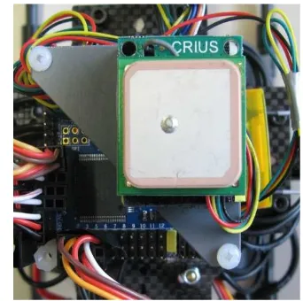
Figure 1. Single frequency receiver u-blox NEO-6M with antenna
As default GNSS sensor small, lightweight and cost-effective L1 single frequency receivers are used, such as the LEA-6S or NEO-6M by u-blox (Fig. 1). Those highly sensitive receivers can deliver positions with a data rate of up to 10 Hz. Even under difficult reception conditions it is possible to receive the signals from the GPS satellites and the correction data of SBAS satellites to achieve a positioning accuracy of up to 1 m under good conditions. These accuracies are to be considered in the control algorithms for the waypoint navigation. Thus a flight guidance is possible under favorable weather conditions in the range of approximately ±5 m.
1.3 Software requirements
The sensors and microcontroller software used for the control, navigation and orientation of the UAV can be adapted and optimized to various needs. For the Bochum project a Multicopter has been applied with software written in C, freely available under GNU GPL v3 license terms, so it can be used on different microcontrollers (Fig. 2). The system can thus be adapted to own requirements and applications and further improvements are possible (Multiwii 2013). E. g. the impacts of approximated formulas used for the calculation of parameters, like the barometric height or orientation angles, are going to be analysed.
Figure 2. MultiWii-Software Interface
The relevant parameters of all connected sensors can be visualized, as well as variations of sensor values are shown and logged in real-time.
2. PRECISE POSITIONING 2.1 GNSS Sensors
Higher accuracy up to centimeter is accessible only by use of RTK-capable dual-frequency GNSS sensors. A major problem is the size and the weight of the dual-frequency receivers and their antenna. Within the Multicopter project a light and airworthy GNSS hardware was searched to replace the single frequency receiver. The first solution found consists of a dual frequency GNSS receiver OEM1 of TOPCON (size: 60 x100 x 13 mm) in connection with an airworthy dual frequency antenna Maxtena M1227 HCT (50 mm x 30 mm) (Fig. 3). The OEM1-receiver circuit integrates 72 universal channels (GPS: L1 (C/A & P), L2, L2C; GLONASS: L1 (C/A & P), L2 (C/A & P); SBAS: WAAS/EGNOS/MSAS).
Three serial ports, a USB as well as a CAN interface can be configured differently with data rates of up to 100 Hz. For the Multicopter application a serial interface is used to provide the NMEA data for the flight control. The second interface is utilized to transmit the data in RTCM 3.0 format (for improved
real-time navigation and for post-processing) via a radio module to a ground station, and recorded there. The entire equipment only weights 150 g, including the GPS antenna and the radio module.
Figure 3. TOPCON dual frequency receiver OEM1 with XBEE radio module and dual frequency antenna Maxtena
M1227HCT-A-SMA (optional: 360°miniprism for target tracking with a tachymeter)
As a result of a further miniaturization Topcon recently developed the B110 receiver board (size: 40 x 55 x 10 mm), distributed for a few months (Fig. 4). This ultra-compact positioning engine is capable of providing scalable positioning from sub-meter DGPS positioning to sub-centimeter RTK positioning (Topcon 2013). All available GNSS systems are supported, as well as the prospective Galileo and COMPASS. The integration of an SD/MMC card interface supports data logging with 20 Hz writing rate and up to 2 GByte capacity. This is a fundamental need for post-processing. A major feature is the direct disposability of an event signal which can be used to synchronise the exposure time with the GNSS time. This data can be additionally logged in an NMEA format.
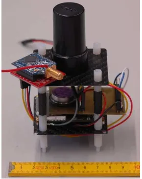
The available B110 development kit includes the evaluation board, software and cables to customise own rovers. Fig. 5 shows the adaption of the board and additional components (weight: 100 g) to a Quadrocopter-platform.
Figure 4. TOPCON dual frequency receiver B110
Figure 5. B110 receiver mounted to a Quadrocopter-platform
2.2 GNSS Software
For precise georeferencing improved position data can be calculated in postprocessing by using the GNSS raw data, recorded during the flight in conjunction with the data of a reference station. For this purpose the RTKLIB program library is used (Takasu 2009, Takasu 2013).
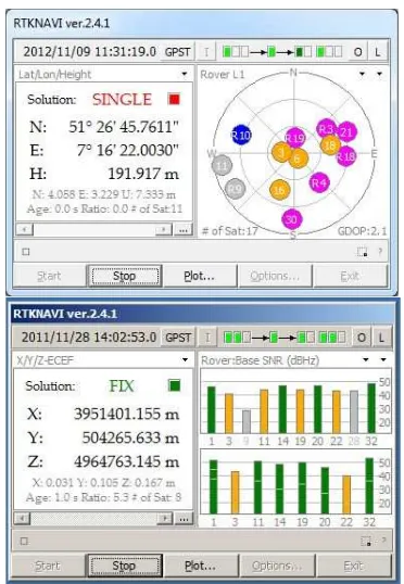
The program processes data of various GNSS systems and can be performed for real-time computation and data recording as well as for post-processing. It is available for multiple data formats and also the raw data of various GNSS receivers. The elevation- and azimuth-dependent corrections of the antennas used can be imported to the program in standard formats. To visualize the data and calculations numerous plot and graphic windows are selectable (Fig. 6).
Figure 6. User interface of the real-time module RTKNAVI
The source code is available in C++ for own developments. For RTK real-time calculations the data can be fed via a serial interface or via network using TCP / IP or NTRIP. In addition RTK positions, calculated in real-time can be output via the
above mentioned interfaces in NMEA format or can be stored with the raw data. Thus it is possible, to return the improved calculated positions of the ground station back to the UAV where it can be used for improved flight navigation.
2.3 Inertial and augmentation Sensors
The terms “inertial and augmentation sensors” subsume all sensors which are necessary to determine the orientation of an UAV and a mounted (image) sensor. This includes MEMS gyroscopes and accelerometers as well as sensors to determine data of its course (triaxial magnetometer) and altitude (barometric sensor). The stabilization of the Multicopter primarily occurs by means of the rotation rate measurements of the MEMS gyroscopes. The triaxial accelerometer is used for position control (leveling) and to determine the roll and pitch angles. The GNSS sensor and a compass module (triaxial magnetometer) are required for waypoint navigation and the so-called coming-home function. An air-pressure sensor is used to determine the barometric height, and together with the coordinates of GNSS for the position hold and the altitude hold function.
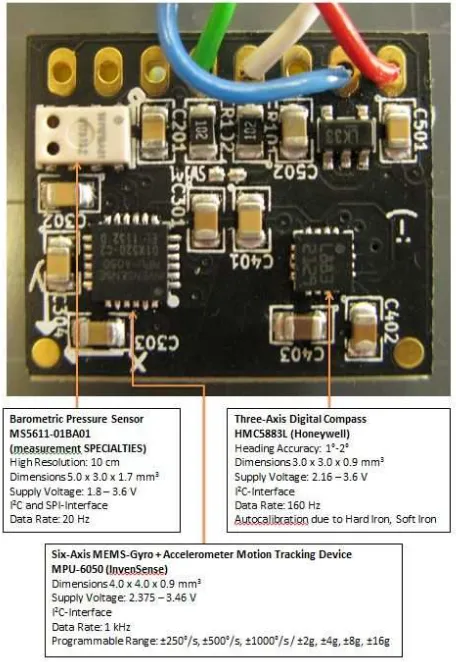
Figure 7. Multi sensor circuit board with microprocessor
The development of MEMS sensors, originally developed for playstations and smartphones, has also influenced geodetic applications (Wild-Pfeiffer & Schäfer 2011, Bäumker 2013) and
Triaxial Magnetometer HMC5883L (Honeywell) Course accuracy: 1°-2° Dimension: 3.0x3.0x0.9mm³ Power supply: 2.16-3.6V I²C-Interface
Data rate: 160Hz
Autocalibration due to mag. noise field (Hard and soft iron)
Barometric sensor MS5611-01BA01 (measurement SPECIALITIES) High resolution: 10cm Dimension: 5.0x3.0x1.7mm³ Power supply: 1.8-3.6V I²C- and SPI-Interface Data rate: 20Hz
Six-Axes-MEMS-Gyro + Accelerometer MPU-6050 (InvenSense)
Dimension: 4.0x4.0x0.9mm³ Power supply: 2.375-3.46V I²C-Interface
Data rate: 1kHz
Programmable effective range: ±250°/s, ±500°/s, ±1000°/s ±2g, ±4g, ±8g, ±16g
3 serial interfaces, e.g. GPS, VCC + GND
in particular triggered the boom of Multicopter significantly and is still going on. The integration of sensors on a single board not only results in a cost-effective manufacturing and mass production, but also offers the use in accordance with small and lightweight UAV's. The newest developments combine on a 50 mm x 50 mm wide board not only the sensors, but also the microcontroller for the flight control and air navigation. Fig. 7 shows the so called “all-in-one” board.
The board and the microcontroller, which is very easily programmable via the integrated USB interface, are equipped with various digital interfaces (3 serial interfaces, I²C-bus) for connecting additional sensors, such as a GNSS and ultrasonic sensor and a telemetry. Further analog outputs are used for motor control and camera control as well as camera stabilization.
To improve reliability a combination with a second sensor board, as shown in Figure 8, is possible. The board can be adapted via I²C-bus to main board (Fig. 7) with the microcontroller. The data of the redundant sensors can be compared continuously and validated.
Figure 8. Multi sensor board with I²C-bus
3. INVESTIGATION OF ORIENTATION QUALITY 3.1 3D-position accuracy
For photogrammetric purposes two main objectives have to be considered: firstly, the positioning, orientation and stabilization of the image sensor at the predefined sites and the release of the camera in time and secondly the acquisition of the position and orientation data for the post-processing to perform the direct georeferencing, for which a time synchronisation of better than 1 ms is needed.
To examine the accuracy of the position of an UAV a miniprism has been additionally installed beneath the UAV. During flight the miniprism has been tracked in real time (up to 10 Hz) by a tachymeter equipped with an automatic target acquisition system (LEICA TS15). After the flight the RTK-positions, calculated in real time by the RTKLIB software using a JAVAD Triumph-1 3GT dual frequency receiver as reference station, were compared with the coordinates derived from the tachymeter measurements. The accuracy of the RTK positions mainly depends on the method wether the ambiguities could be fixed or only a float solution could be calculated.
Figure 9 shows the differences between the RTK positions and positions of the tachymeter. The main differences are caused by the different mounting position of the prism and the GPS antenna. Neglecting these differences accuracies for the 3D-position of < 0.1 m for the ambiguity fixed solution and < 0.5 m for the float solution could be achieved.
Figure 10, which shows a direct KML-export of the RTKLIB software, demonstrates further kinematic RTK measurements with the Topcon OEM1 board on the roof of Bochum University of Applied Sciences. The receiver had been positioned along a linear handrail with data logged at a rate of 10 Hz. For this investigation the handrail could be used as a nearly error-free reference track. The achieved accuracies for the GNSS positions are better than 5 cm, even for the float solution.
Figure 9. Differences between the RTK positions and positions of the tachymeter
Figure 10. Kinematic RTK measurements on the roof of the test building (green: fixed solution, orange: float solution)
3.2 Accuracy of orientation angles
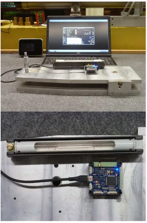
While the accuracy of the attitude angles depends on the stability of the accelerometer bias the accuracy of the heading angles depends on the measurements of the three axes magnetometer and its sophisticated calibration due the disturbances of the environment by hard iron and soft iron and the modelling of the magnetic variation. Lab-tests were performed to achieve the accuracy of the accelerometers in respect to their biases and resolution. The equipment under test had been fixed on a board which could be tilted via a micrometer gauge (Fig. 11). For these purposes the MultiWii software had been modified to acquire and store the raw data of the sensors.
The attitude-angles of the accelerometers, which had been positioned under diametrical and opposite orientations (0°, 180°, upside, upside-down), were compared to those of the gauge. The results are shown in Fig. 12. The saw-tooth pattern shows, as a typical effect, the resolution of the attitude-angles. The systematic differences between the upside and upside-down positions are caused by the non-parallel installation of the IMU and the tilt-board. The examination of the attitude angles shows that during unaccelerated flight phases an accuracy of the attitude angles of 0.1° to 0.2° can be attained.
Figure 11. Mechanical board with a micrometer-srcew for the determination of the resolution of angles
Figure 12. Attitude-angles of the accelerometers compared to a gauge measurement
The heading ψ is derived from the three measurements of the magnetometer (mx, my, mz) which have to be calibrated due to soft- and hardiron disturbances and then transformed into its horizontal components (mhx, mhy) by using the g-vector (Fig. 13). The horizontal components are then used to calculate the magnetic heading ψmag. Finally this angle has to be corrected in respect to the magnetic variation (declination δ).
Thus, under ideal conditions, an accuracy of the heading angle of 0.1° to 0.5° can be achieved. Further examinations and improvements concerning this topic are already in progress.
Figure 13. Determination of the heading angle ψ from magnetometer measurements
As an excellent alternative for measuring the heading component the Topcon GNSS receiver can be equipped with a second (single frequency) antenna. This results in a heading accuracy of 0.1° per meter antenna distance (the typical diameter of a Multicopter matches 0.8 m), which means that under good satellite conditions a relevant improvement can be achieved.
4. CONCLUSIONS
Navigation accuracy is an important requirement for a successful operation of an UAV during its autonomous flight. Lightweight components, GNSS as well as the inertial sensors, are mandatory for this application. Because of these facts high sophisticated systems, as normally used in photogrammetry, are not suited. Comparing with these systems a loss of accuracy is unavoidable.
-0,3 -0,2 -0,1 0,0 0,1 0,2 0,3 0,4
-2,0 -1,5 -1,0 -0,5 0,0 0,5 1,0 1,5 2,0
D
e
lt
a
= I
M
U
G
a
u
g
e
[
d
e
g
]
Attitude Angle [deg] Accelerometer Test
Upside 0° Upside 180° Upside-down 0° Upside-down 180°
The latest standard systems to control UAV are based on all-in-one boards and single frequency GNNS-receivers. The quality of these sensors is sufficient for flight control and standard navigation (5 m to 15 m), but often results in problems when performing an aerial flight, especially concerning the overlapping parameters.
To improve this aspect different GNSS-receivers and evaluation concepts had been examined. As could be shown lightweight and airworthy dual frequency GPS-receivers in combination with free GNNS positioning software allow to establish a kinematic GPS solution with accuracies within the cm-level. This is a mandatory assumption for an aerotriangulation with a reduced number of control points (Ackermann 1997) and equivalent to a partial direct georeferencing of the UAV. Besides the position accuracy for a direct georeferencing the accuracy of the orientation angles which have to be derived from the attitude and heading angle and its synchronisation to the images are very important. While the synchronisation of the images is easily possible by using the event input of the GNSS receiver the calculation of the orientation angles is still a challenge. In a first step the accuracy of the angles of the All-in-one-Boards has been evaluated. The examinations show that the attitude could be calculated with an accuracy of 0.1° to 0.2° and the heading angle with 0.1° to 0.5° which can be additionally improved using a GNNS receiver with two antennas. It can be expected that the accuracy of the inertial sensors will increase in the nearby future.
Further improvements seem to be possible by using two or more sensor boards. This might result in a higher accuracy and has the advantage to establish a redundant system.
Further investigations will deal with this application area.
5. REFERENCES References from Journals:
Ackermann, F., 1997. Geo-Kodierung ohne Paßpunkte, GIS -
Geo-Informations-Systeme, Vol. 10(2), pp. 28-32.
Bäumker, M., 2013. Hybride Navigationssysteme für Navigation, Regelung und Direkte Georeferenzierung.
Zeitschrift für Vermessungswesen (ZfV), Vol. 5/2013. In print.
Wild-Pfeiffer, F., Schäfer, B., 2011. MEMS-Sensoren, auch für die Geodäsie, Zeitschrift für Vermessungswesen (ZfV), Vol.
1/2011, pp. 30-39.
References from Other Literature:
Adler, B., Xiao, J, 2012. Towards Autonomous Airborne Mapping of Urban Environments. 2012 IEEE International Conference on Multisensor Fusion and Information Integration
(MFI 2012), pp. 77-82, Hamburg, Germany, Sept., 2012.
Bäumker, M., Brechtken, R., Heimes, F.-J., Richter, T., 1999. Direkte Georeferenzierung mit dem Luftaufnahmesystem LEO. In: Proceedings 10. Internationale Geodätische Woche,
Obergurgl, 21.2.-27.2.1999.
Bäumker, M., Ludwig, J. 2007. "eagle eye technologies" - ein kinematisches terrestrisches photogrammetrisches Stereo-aufnahmesystem mit direkter Georeferenzierung mittels INS, GPS und Odometer. In: Proceedings 14. Internationale
Geodätische Woche 2007, Obergurgl/Ötztal, 11.-16.2.2007.
Brechtken, R., Borchert, R, Przybilla, H.-J. & Roderweiß, M., 2012. Auswertung von Bilddaten aus UAV-Flügen – Von der klassischen Aerotriangulation zum Dense Image Matching.
Terrestrisches Laserscanning - TLS 2012. Proceedings 121.
DVW-Seminar in Fulda, DVW Journal, Vol. 69, ISBN
978-3-89639-899-4
Bäumker, M. & Przybilla, H.-J., 2011. Investigations on the quality of the navigation data of Unmanned Aerial Vehicles using the example of the system Mikrokopter. International Archives of the Photogrammetry, Remote Sensing and Spatial
Information Sciences, Vol. XXXVIII-1/C22, ISSN 1682-1777,
September 14-16, 2011.
Bäumker, M., Przybilla, H.-J. & Zurhorst, A., 2012. Enhancement Of The Navigation Data Quality Of An Autonomous Flying Unmanned Aerial Vehicle For Use In Photogrammetry. 3rd International Conference on Machine
Control & Guidance, Stuttgart, March 27-29, 2012.
Bäumker, M., Przybilla, H.-J. & Zurhorst, A., 2013. Mikrokopter – Einsatz von UAVs in der Photogrammetrie. 17.
International Week, Obergurgl 2013, ISBN 978-3-87907-526-3,
pp. 28-39
Nüchter, A., Elseberg, J., Borrmann, D., 2013. Optimale 3D-Punktwolken aus mobilen Laserscandaten. In: Luh,mann/Müller (Editors): Photogrammetrie, Laserscanning, Optische 3D-Messtechnik. Beiträge der Oldenburger 3D-Tage 2013, ISBN 978-3-87907-528-7, pp. 186-193
Sternberg, H., Keller, F. & Willemsen, T., 2013. Nutzung von Smartphones in der Indoor-Navigation. International Week,
Obergurgl 2013, ISBN 978-3-87907-526-3, pp. 216-227
Takasu, T., 2009. RTKLIB: Open Source Program Package for RTK-GPS, FOSS4G 2009 Tokyo, Japan, November 2, 2009
References from websites:
Multiwii, 2013. Website MultiWii Project,
http://www.multiwii.com, (April 2013)
Takasu, T., 2013. RTKLIB: Open Source RTK-Program Package for GNSS Positioning, http://www.rtklib.com, (April 2013)
Topcon, 2013. Website Topcon OEM GNSS Boards. http://oem.topconpositioning.com/oem-products/gnss-boards (April 2013)
Acknowledgements
Thanks to Topcon Europe Positioning B.V., especially Markus Geiß and Alexander Vyrsky, for supporting our investigations with the B110 board.