OBLIQUE AERIAL IMAGES AND THEIR USE IN CULTURAL HERITAGE
DOCUMENTATION
Joachim Höhle
Dept. of Planning, Aalborg University, Vestre Havnepromenade 5, DK-9000 Aalborg – [email protected]
Commission V, WG V/2
KEY WORDS: Cultural Heritage, Multisensor, Multispectral, Quality, Matching, Point Cloud, Modelling, Photo-realism
ABSTRACT:
Oblique images enable three-dimensional (3d) modelling of objects with vertical dimensions. Such imagery is nowadays systematically taken of cities and may easily become available. The documentation of cultural heritage can take advantage of these sources of information. Two new oblique camera systems are presented and characteristics of such images are summarized. A first example uses images of a new multi-camera system for the derivation of orthoimages, façade plots with photo texture, 3d scatter plots, and dynamic 3d models of a historic church. The applied methodology is based on automatically derived point clouds of high density. Each point will be supplemented with colour and other attributes. The problems experienced in these processes and the solutions to these problems are presented. The applied tools are a combination of professional tools, free software, and of own software developments. Special attention is given to the quality of input images. Investigations are carried out on edges in the images. The combination of oblique and nadir images enables new possibilities in the processing. The use of the near-infrared channel besides the red, green, and blue channel of the applied multispectral imagery is also of advantage. Vegetation close to the object of interest can easily be removed. A second example describes the modelling of a monument by means of a non-metric camera and a standard software package. The presented results regard achieved geometric accuracy and image quality. It is concluded that the use of oblique aerial images together with image-based processing methods yield new possibilities of economic and accurate documentation of tall monuments.
1. INTRODUCTION
The use of oblique photographs is as old as photogrammetry. The famous cartoon where the Frenchman G.-F. Tournachon (aka “Nadir”) is photographing Paris from a balloon is known to many people. This was in 1863. Nowadays all imaging is digital and aerial imagery is also taken from airplanes, helicopters, and unmanned aerial systems (UAS). Oblique images enable the recording of historical objects with a vertical extent. Such images are used for the production of 3d photorealistic models and façade plots as well as for the determination of the materials of which the object is built. Oblique aerial images are usually taken more than 100m away from the object. Nevertheless, small details have to be detected and recorded with high accuracy and completeness. High image quality is therefore important. Other requirements in documentation of historical sites concern low costs for acquisition of images, determination of ground control and processing. The procedures to be carried out should be simple and to great extent automatic so that also non-photogrammetrists can carry out the task. A great development took place in the design of cameras and the application of the Internet for viewing and distribution of imagery. New camera systems integrate several oblique cameras with a nadir camera. Cities are systematically photographed by means of such cameras and images of high quality are at disposal on the Internet. This new possibility and the announcement of two new multi-camera systems started this investigation. The generation of 3d city models is a current task for photogrammetric companies and organizations. Such tasks have similarities with the recording of cultural heritage. The goals of this article are to apply these innovations (cameras, processing software, Internet)
for tasks in the documentation of cultural heritage. The characteristics of oblique images will be summarized and the experiences from two practical tasks will be presented and discussed.
2. CAMERAS AND SENSOR SYSTEMS
The mapping cameras of today are digital cameras. New frame cameras have up to 260 million pixels and collect images in four different bands. New is the increased use of multi-head cameras which take oblique images in different directions. These systems comprise also sensors for positioning (GNSS) and attitude determination (IMU). Examples are the solutions of Track Air (MIDAS), Pictometry, and BSF Swissphoto (AOS). Details about these camera systems and processing of such images are described in (Madani, 2012; Höhle, 2008; Wiedemann, 2009). New multi-camera systems have recently been produced by Leica and Microsoft.
2.1 Leica RCD30 Oblique camera
The camera system is available in different configurations. A pod can hold either three or five cameras. The five camera version (RCD30 Oblique Penta) is described in the following. The camera axes of four oblique cameras are tilted by 35° and images are taken to both sides of the flight line and forward and backward in flight direction. The fifth camera takes nadir images. The oblique images overlap with the nadir image. Their lenses have a focal length of 50mm. The size of the sensor (CCD) is 8956 x 6708 pixels. The nadir camera has two CCDs, one for the red (r), green (g), blue (b) bands and one for the International Archives of the Photogrammetry, Remote Sensing and Spatial Information Sciences, Volume XL-5/W2, 2013
near-infrared (n) band of the spectrum. The size of the pixel is 6µm x 6µm. The shortest time interval between exposures (maximum frame rate) is 1.8 seconds. Image motion is compensated mechanically in two axes. A gyro-stabilized mount can be used which will prevent big tilts of the nadir images.
2.2 Microsoft UltraCam Osprey
The new camera of the photogrammetry division of Microsoft produces a panchromatic nadir image of high resolution (11674 x 7514 pixels with a size of 6µm x 6µm) which may then be ‘colourized’ by means of red, green, blue and near-infrared images of lower resolution (6870 x 4520 pixels). The focal lengths of the nadir camera and of the oblique cameras are different (51mm and 80 mm respectively) so that the oblique images have about the same scale as the nadir image. The oblique forward and backward images are each ‘stitched’ together of images from two cameras so that the large image size of 70mm against flight direction (swath width) is the same as in the nadir image. The maximum frame rate is 2.0 seconds.
3. CHARACTERISTICS OF OBLIQUE AERIAL IMAGES
Oblique aerial images can be characterized by ground sampling distance, image quality, and overlap. Some basic knowledge about these features will be presented in the following.
3.1 Ground sampling distance
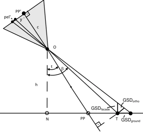
Photography with a tilted camera axis of flat terrain results in imagery with variable scale. The size and the form of the image element (pixel) on the object vary too. It depends on the position in the scene and the shape of the object. In order to characterize an oblique aerial image the size of the pixel orthogonal to the camera axis is usually quoted. The value (aka ground sampling distance or GSD) is different in the front and the back of the foot print of the oblique image. The general formula for the GSDortho is given by
β
where pel’=pixel size in image, h=flying height above ground, c=camera constant, t=tilt of camera axis, β=angle between a direct line from the lens to a target and the vertical. The difference between the two angles (β-t) is found from the position in the image (y’) and the camera constant by
) They may be determined by the following equations:
β
Figure 1 depicts the parameters and the various GSD values. The GSD is a value for the geometric resolution and two to three GSDs determine the smallest object which can be seen and measured in the image or in the derived pictorial products. The pixels at the object are not squared. The factor between the sides are GSDfaçade /GSDortho = cos(β-t)/sinβ and GSDground/GSDortho= cos(β-t)/cosβ.
Figure 1.Variations in pixel size in oblique images.
O…perspective centre, N…nadir point, PP’…principle point of image, T…target point, GSD…ground sampling distance.
3.2 Image quality
Oblique aerial images are taken from airplanes, helicopters and UAS. The forward motion of the camera may cause blurred images if the exposure time is too long. Facilities for compensation of image motion are designed for high-end camera systems. The theoretical image motion (Δs’) can be calculated by means of formula (5).
'
where v=velocity, Δt=exposure time, pel’=size of the pixel, and GSD=ground sampling distance.
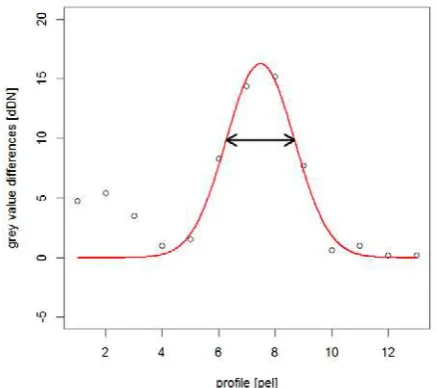
Especially at large image scales (small GSD) the images may be blurred which will affect the results of manual mapping or automated processing. Good image quality is important for good results and should therefore be checked. Image quality can be determined by deriving the so-called Point Spread Function (PSF). In places where an image has edges and contrast profiles across the edge are taken. The border between dark and bright parts in the image spreads over several pixels. The course of the grey values can be plotted and analysed (cf. Figure 2). The changes in the intensity values (dDN) can be modelled by a Gauss-bell curve (cf. formula 6).
β
2 2
) (
σ µ
σ
⋅− −
⋅ =
x
e k
y (6)
The curve has three parameters (k, σ, µ) which are determined by least squares adjustment. The size of the parameter ‘σ’ represents half of the width of the curve at the points of inflection (cf. Figure 3). It is a measure for the image quality. High image quality has σ=1.0, poor image quality has σ>1.2. The value can be derived at edges where the intensity in several profiles orthogonal to the edge are extracted and averaged. The value ‘σ’ may be interpreted as ‘scale factor of effective pixel size’ (Jacobsen, 2008). The value depends on the contrast and the K-value should therefore be determined together with the σ -value.
Figure 2. Course of intensity (grey) values in a profile across an edge of high contrast
Figure 3. Point Spread Function derived from differences in intensity (grey) values in a profile. The line with two arrows represents 2·σ
A program for extracting of profiles and determination of the effective pixel size has been developed by the University of Hannover (Jacobsen, 2010) and will here be used for imagery of the applied cameras and of the derived products.
3.3 Metric and radiometric quality
In order to reconstruct the bundles of imaging rays the parameters of the cameras have to be known. Especially the position of the principle point (PP’) has to be very accurate at photogrammetric point determination with oblique imagery. A calibration of the cameras in situ may become necessary when the camera is not stable under different environmental conditions. Also a good radiometric quality is of concern when images have to be mosaicked or classified. The intensity values of an imaged object should be the same in different images.
3.4 Overlap and coverage
Automated point determination is based on stereo models. The overlap of images determines the base/height ratio which influences the accuracy. It is controlled by the time interval between exposures. The standard forward overlap is 60%. The shape of the overlap area is a trapeze. The tie points between images have to be selected in the corners of the overlap area. The overlap between strips should also have the same percentage. If this is not the case the point clouds have to be derived from the oblique images looking forward or backward in the flight line. This may lead to difficulties in the matching of corresponding points because the scale within the oblique images is variable.
4. APPLICATIONS OF OBLIQUE AERIAL IMAGES IN CULTURAL HERITAGE DOCUMENTATION
4.1 General
The documentation of cultural heritage has different requirements regarding accuracy, completeness, and level of detail. When oblique aerial imagery is applied, high demands exist for the cameras. For example, when images are taken from a distance of 833m with a 50mm lens, one pixel side of 6µm corresponds to 10cm at the object. The object of interest has to be photographed from many different positions in order to document accurately and completely. The processing of the images to photorealistic 3d models and façade plots should apply procedures which should be easy to handle. The work involved should be carried out quickly and at low costs. In the following, some experiences with documenting of historical objects are presented.
4.2 Modelling and visualization of a church from oblique and nadir imagery
In this example the new Leica oblique camera system is applied. It is a metric multi-camera system with some unique features. Imagery of this camera system and ground control was at disposal and used for documentation of a complex cultural monument.
4.2.1 Description of object and data
The object of interest is a church in Switzerland, which is classified as a cultural monument of category B. The building has bright façades and dark roofs, both with very little structure. Small and high towers overtop the roof. The building is International Archives of the Photogrammetry, Remote Sensing and Spatial Information Sciences, Volume XL-5/W2, 2013
surrounded by trees, bushes and other buildings. Oblique and nadir images were taken in June 2012 at noon time. Flying took place in north-south-direction, 670m above ground, and with a velocity of 150km/h. Exposure times of the investigated images varied between 1/500 and 1/800 seconds. The distances between exposures within a strip were about 212m; the distance between flight lines was 430m. The GSD of the nadir image is 8cm and 11cm in the middle of the oblique image. The GSDortho values at the front and back parts of the oblique image are GSDfront=7cm and GSDback=13cm respectively. The supplied images have a radiometric resolution of 8bits per channel and are stored in TIFF format. Dark shadows at the northern parts of the church reduced contrast and details in the images. The theoretical image motion was less than one pixel. Two oblique images were investigated regarding their point spread function (cf. Table 1). The calculated factors for effective GSD are the average of three edges of which 30-60 profiles were analysed. The position in image (in per cent of the maximum image radius), type of object, and contrast (K) are quoted in addition. The used oblique images have a factor of σ=1.06 which does not increase the GSD very much.
Table 1. Results of edge analysis in RCD30 Oblique images image
4.2.2 Derivation of orientation data
A block of 21 oblique images covering the area of the church was selected and georeferenced by means of eight ground control points situated in the corners of the block. Image coordinates of tie and control points were measured in the program “Adobe Photoshop, v. 12.1”. The exterior orientation of all images and the interior orientation of four oblique cameras were determined using the “DGAP” software package of the Institute of Photogrammetry at Stuttgart University (Stallmann, 2008). The orientation angles have been chosen with azimuth (α), nadir distance (t) and kappa (ϰ) which simplified the calculations. Approximations for the coordinates of the perspective centres and the orientation angles have been applied. The orientation data were derived in a joint adjustment. The obtained standard deviation (σo a posteriori) was 1.2 pixels. This means that new points may be determined with an accuracy of about σE,N =13cm. The derived camera constants deviated only slightly from the values provided by the producer.
4.2.3 Processing of info clouds
The generation and editing of point clouds were carried out with the professional programs “ApplicationsMaster”, “Match-T”, and “DTMaster” of the Inpho Company. Several stereo-pairs were processed. An adaptation of orientation data to the coordinate systems applied in “Match-T” is necessary. A polygon around the church is digitized in the stereo model. The processing of the point cloud takes place only for this area. A regular grid of elevations was generated from the point cloud. The spacing of the grid was selected with 0.50m and 0.25m. A denser grid will make the handling of the data more difficult and increase computing times. The matched points are supplemented with some attributes. Adding of colour information to each point enables an easy generation of
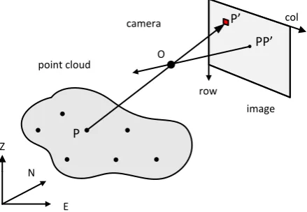
orthoimages and other pictorial products. The principle is depicted in Figure 4. It is necessary that the point density is relatively high and that no gaps are present in the DSM. Gaps are the result of automated filtering. They have to be filled by interpolation using remaining DSM points around the gaps. Such editing of the DSM occurred automatically, but some manual editing was necessary.
O
Figure 4. Principle of adding colour information to point clouds by means of back projection. O…projection centre, col…column of image matrix, PP’…principle point of camera
4.2.4 Derivation of façade plots with photo texture
The derived point cloud with a grid in the Easting/Northing (EN-) plane was not very dense inside the façade. The façade plot with photo texture requires a regular grid with a small spacing. The grid depicted in Figure 5 is defined in a rotated coordinate system, of which the y-axis corresponds to the base line (1-2) of the façade. The azimuth of the façade was derived (modelled) by means of regression. The colour values of each pixel (r,g,b-values) are found in the oblique image using back projection by means of the collinearity equations. The coordinates of the pixels (cells) and of the perspective centre have to be in the same system which requires a transformation of the grid to the EN-system. The façade with photo texture can thereafter be plotted in the yZ-system (cf. Figure 6). The analysis of edges within the façade revealed factors of σ=1.11 which may increase the GSD from 16 to 18cm. Windows, doors, and other features inside the façade can be recognized, measured or mapped. Features in front or behind the selected plane will be displaced. Such inaccuracy may be avoided when the object is modelled by small planes.
4.2.5 Dynamic 3d models
The representation of the modelled church (or parts of it) in 3d and with photo texture can be realized by the freeware software package “vrmlgen” (Glaab et al., 2010). A 3d viewer enables navigation through the 3d model stored in Virtual Reality Markup Language (VRML). It requires pretty powerful computers to realize the movements in the virtual 3d space for the whole photorealistic model of the church. Photo texture has been added for each of the points after the principle depicted in Figure 4. In this point cloud with colour attributes many points can be removed by filtering with the result that no regular structure of the points is present in the yZ plane. Only after modelling of planes such a regular pattern can be generated as described in section 4.2.4. The 3d models in web formats such as VRML, X3D, COLLADA, or KMZ may also be viewed on the Web.
P'
P
E N
y x
2 1
flight line
Z
y
1 2facade grid
pel
OFigure 5.Principle in the derivation of façade plots with photo texture. A regular grid of small pixel size (pel) is established in the modelled yZ-system and supplemented with colour (r,g,b-values), which are found in the image by back projection (P→P’).
Figure 6.Façade plots with photo texture derived from oblique aerial images taken from East and North of the church. A pixel size at the façade of 10cm was selected.
4.2.6 Derivation of orthophotos
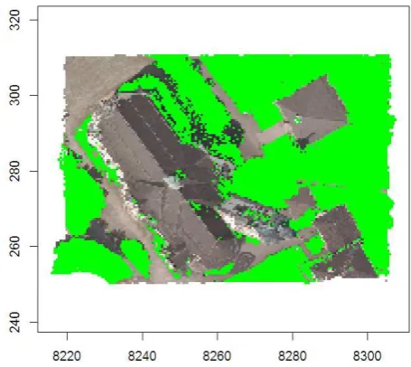
Orthoimages can easily be derived from nadir images using colourized point clouds. The spacing between the DSM points has to be small. One GSD would be optimal in order to maintain the resolution of the original image. The geometric accuracy of such an orthoimage is better than a standard orthoimage which is based on a DTM. Several orthoimages were produced and used for the determination of azimuth angles of building façades. The generation of orthoimages by means of oblique images has to overcome several problems. Double image parts and hidden image parts may be produced. Surrounding vegetation may hide parts of the monument to be modelled. To overcome these problems a visibility analysis has to be carried out. A complete 3d model of the monument has to be available, however. Another approach is the removal of the vegetation by means of image processing techniques. The nadir images of the used RCD30 oblique camera comprise four bands. The additional near-infrared channel makes false colour images possible. It is imaged by the same lens and has therefore the same orientation. The colourized point cloud may have four intensity numbers (r,g,b,n) and can be used to remove vegetated areas from the DSM. For each point of the DSM the normalized
density vegetation index (NDVI value) is derived. Points with an NDVIvalue bigger than a threshold (e.g., NDVI>0.1) are
Figure 7. Orthophoto with detected and visualized vegetation
classified as vegetation. The resulting orthoimage is depicted in Figure 7. The vegetated areas are visualized in green colour.
4.3 Recording an ancient citadel by means of oblique images from air and ground
The object of documentation is a fortification consisting of houses, walls, and gates. It is situated in Erbil, Iraq, and is on the list of UNESCO’s most endangered historic sites. The documentation and restoration work was carried out by Czech universities and several publications exist about this work, inter alia the dissertation of V. Králová, a former PhD student of CTU in Prague. The author of this paper got involved in the processing of the images during Královás ERASMUS internship at Aalborg University. The characteristics of the photogrammetric surveying and visualization are summarized in the following.
4.3.1 Description of data and results
Oblique images were taken from a helicopter by means of a non-metric camera (Canon EOS 20D) equipped with a zoom lens (EF-S 17-85mm). The focal length has been set to 17mm and images were taken with GSDortho≈5cm. 34 oblique aerial images and 19 terrestrial images were processed by the program “PhotoModeler” of EOS Systems Inc. Tie and ground control points were manually measured and orientation data of the images and of the camera were calculated. Corner points of plane areas were thereafter determined semi-automatically. A wire frame model consisting of 3500 points and a few hundred lines have been created. Its accuracy has been determined from a few check points with RMSEX =0.13m, RMSEY =0.31m, RMSEZ =0.30m. Parts of the wire frame model have been textured with image contents. Closed polygons defining a plane had to be created. The image texture was then transferred by a perspective transformation. The photorealistic model has been coupled with a data base containing information about each building in the fortification. The 3d model and the contents of the database can be viewed and edited on the Internet. More details on the photogrammetric and visualization work can be found in (Pavelka et al., 2007) and (Králová, 2008).
4.3.2 Checking the quality of the images
In context of this paper the quality of the imagery and of the photorealistic façade plots is of interest. The helicopter flew with a velocity of 10m/seconds and exposure times differed between 1/250 and 1/500 seconds. This results in a theoretical image motion of Δs’max≈ 5.2µm or 0.8·GSD. The edge analysis as described in section 3.2 revealed factors for the effective GSD of σ=1.16 (average of two images and six edges). The difference in the effective pixel size is 0.4·GSD only (cf. Table 2). This means that the calculated theoretical image motion is not reached and that the image quality is not very much deteriorated by image motion. Edge analysis of the textured façade plot revealed a factor of σ=1.15 which is in agreement with the factor derived from the original images.
Table 2. Results of edge analysis in Canon EOS 20D images image
type & number
object type & position in image
[%]
K σ
nominal GSD [cm]
effective GSD [cm]
oblique 64
façade
62 0.46 1.30 5 7
oblique 65
façade
21 0.38 1.02 5 5
5. DISCUSSION
Two different examples are presented. The first one uses a metric multi-camera system. The camera system is very compact and can be installed in pods for airplanes, helicopters and UAS. It produces simultaneously four oblique images and one nadir image of a high geometric and radiometric quality. Thanks to the high geometric accuracy and stability of the cameras the amount of ground control points as well as the efforts for a re-calibration can be reduced. The used bundle adjustment determined the interior orientation for all cameras, the exterior orientation data of all images, and the coordinates of new points simultaneously. The applied parameters for angles (α,t,ϰ) made the finding of approximations simple and the calculation of unknowns more stable. The applied methodology for modelling derives very dense point clouds and adds colour and other attributes to each point (cell). Orthoimages and façade plots can then easily be produced. The colour information is obtained by back projection. Other attributes can be added to all points which enable classification and visualization of vegetation. A modelling of the surface of the object by planes, cylinders, and other geometric bodies has to be carried out when a regular and dense point cloud cannot be derived due to lack of structure and contrast in the images. The overlap between strips should be 60% so that stereo pairs can be used in the direction of flying. The use of stereopairs consisting of forward or backward looking images is also possible. The derived DSM may be incomplete and less accurate due to scale differences within the two images. The visualization of the 3d model by means of photo texture should use the accurate orientation data of the images derived by aerotriangulation instead of calculating transformation parameters for each single surface of the wireframe model using three or more reference points. The second example is more complete and supplemented with a database which stores information on parts of the monument. Both examples are created with a lot of manual work. Efforts for automation of the procedures should follow.
6. CONCLUSION
The recording of historical monuments can with advantage use oblique aerial images. Details in the vertical dimension can be seen, recorded and visualized. It is anticipated that such imagery will be available when cities are systematically recorded as it is already the case with several multi-camera systems. Metric cameras have advantages in the processing of the data. The potential of the applied multi-camera system may be improved when the oblique cameras have longer focal lengths than the nadir camera. For example, when a focal length of foblique= fnadir·1/cos(t) is applied both camera types will produce images with approximately the same GSD. The oblique images should also be multispectral. A 3d model with photo texture and additional information in a linked database (as it is realized in the second example) can be viewed and edited on the Internet. Cooperation between archaeologists, photogrammetrists, and other specialists can thereby take place over distances. Improvement and maintenance of the documentation are then possible.
REFERENCES
Glaab, E., Garibaldi, J.M., Krasnogor, N., 2010. Vrmlgen: An R package for 3D visualization on the Web. Journal of Statistical Software, volume 36, issue 8, 18 p.,
http://www.jstatsoft.org/v36/i08/paper (accessed 15 June 2013)
Höhle, J., 2008. Photogrammetric measurements in oblique aerial images. Photogrammetrie, Fernerkundung, Geoinformation, issue 1, pp. 7-14.
Jacobsen, K., 2008. Tells the number of pixels the truth? - Effective resolution of large size digital frame cameras. Proceedings of ASPRS annual conference, Portland, Oregon/USA, 7 p.
Jacobsen, K., 2010. Manual of the program “Edge”, 9 p.
Králová, V., 2008. Application of digital photogrammetry, modern visualization methods and GIS technology for monument preservation. Dissertation, Czech Technical University in Prague, 133 p.
Madani, M., 2012, Accuracy potential and applications of Midas aerial oblique camera system. International Archives of the Photogrammetry, Remote Sensing and Spatial Information Sciences, Volume XXXIX-B1, pp. 127-132.
Pavelka, K., Králová, V., Svatušková, J., 2007. Photogrammetric documentation and visualization of Choli Minaret and Great Citadel in Erbil/Iraq. Proceedings of CIPA 2007, pp. 245-258.
Stallmann, D., 2008. DGAP Notes, 96p. http://www.ifp.uni-stuttgart.de/publications/software/openbundle/index.en.html
(accessed 15 June 2013)
Wiedemann, A., 2009. Photogrammetrische Schrägluftbilder mit dem Aerial Oblique System AOS. Proceedings of DGPF-Jahrestagung, Volume 18, 8p.
ACKNOWLEDGEMENTS
Leica Geosystems and prof. K. Pavelka, CTU in Prague, are thanked for providing imagery and ground control for these investigations.