A MICRO-UAV WITH THE CAPABILITY OF DIRECT GEOREFERENCING
Martin Rehak, Romain Mabillard, Jan Skaloud
TOPO Lab, École polytechnique fédérale de Lausanne (EPFL), Lausanne, Switzerland {martin.rehak, romain.mabillard, jan.skaloud}@epfl.ch
http://topo.epfl.ch
KEY WORDS: UAVs, MAVs, Photogrammetry, Sensor Orientation, Direct Georeferencing
ABSTRACT:
This paper presents the development of a low cost UAV (Unmanned Aerial Vehicle) with the capability of direct georeferencing. The advantage of such system lies in its high maneuverability, operation flexibility as well as capability to acquire image data without the need of establishing ground control points (GCPs). Moreover, the precise georeferencing offers an improvement in the final mapping accuracy when employing integrated sensor orientation. Such mode of operation limits the number and distribution of GCPs, which in turns save time in their signalization and surveying. Although the UAV systems feature high flexibility and capability of flying into areas that are inhospitable or inaccessible to humans, the lack of precision in positioning and attitude estimation on-board decrease the gained value of the captured imagery and limits their mode of operation to specific configurations and need of ground-reference. Within a scope of this study we show the potential of present technologies in the field of position and orientation determination on a small UAV. The hardware implementation and especially the non-trivial synchronization of all components is clarified. Thanks to the implementation of a multi-frequency, low power GNSS receiver and its coupling with redundant MEMS-IMU, we can attain the characteristic of a much larger systems flown on large carries while keeping the sensor size and weight suitable for MAV operations.
1. INTRODUCTION
Low-cost and low-weight UAV systems with imaging capability have enjoyed a rapid development over the several past years and are increasingly deployed as carries for measuring purposes. They present a considerable potential for local-area remote sensing applications in the fields of agriculture, forestry, mining, hydrology as well as in the scientific research. Although these systems allow a new way of data collection in the field of geomatics, they inherit an old (i.e. indirect) approach to sensor/image orientation. Indeed, most of the commercially available micro-UAVs carry simple non-metric cameras and GNSS receivers that do not allow reliable sensor orientation with cm-level and arc-minute accuracy in position and attitude, respectively. Hence, the missions with the need of accurate mapping and thus sensor/image orientation require image acquisition in a block-structure with large forward and side overlaps, the existence of (possibly many) ground-control points (GCPs) as well as the lack of uniformity in the surface texture. (Note that although single-strip operations are theoretically possible, the requirement on the number and distribution of GCPs makes them impractical). Overall, these requirements limit firstly the mapping productivity of a micro-UAV (e.g. due to the establishment of large number of GCPs), secondly, its area of operation outside corridors and surfaces of homogeneous texture such as dense vegetation or, in the worst case scenario, water/costal areas.
1.1 Motivation
In this paper we study the problematic of GPS/INS sensor integration for precise sensor orientation on a MAV multicopter. Although the current trend is biased to the non-direct approach, we can see a gradual rise up in the field of advanced sensor integration into larger UAV platforms (e.g. Swiss Drone). In certain sense this evolution follows the
classical airborne photogrammetric development (Colomina, 2012) to which direct sensor orientation was conceptually introduced in the early nighties(Schwarz et al., 1993)together with the first experimental confirmation in photogrammetry (Skaloud et al., 1994). The progress in the field of miniaturization of the inertial technology as well as GNSS receivers and antennas allows in principle create a small integrated system from of-the-shelf components. Nevertheless, these need to be combined with the state-of-the-art processing to respond to the accuracy requirements for direct or integrated sensor orientation.
1.2 Objectives
The problematic of direct georeferencing or direct sensor orientation has been already extensively researched in the classical airborne photogrammetry (e.g. Skaloud, 1999), however, only few published studies discuss this problematic in the context of MAV (Blaha et al., 2011, Bäumker et al., 2011, Pfeifer et al., 2012 or Eugster and Nebiker, 2008).
The main aim of our work is a development of a new MAV and its adaptation for this specific mode of mapping operation. Besides the design and construction of a new UAV, the goal of this research is to integrate advanced navigation devices, i.e. a multi-frequency/constellation GNSS receiver and redundant MEMS-IMU and synchronize their operation with the imagery obtained from a medium format digital camera to assign the parameters of exterior orientation to all images with sufficient precision.
1.3 Problem Formulation
without the use of traditional ground-based measurements (Mostafa, 2001).Nowadays, MAV systems are usually equipped only with a single frequency GPS receiver without the precise phase observations. Depending on the geometry of satellites this provides position determination at level of several meters in optimal conditions. That is indeed insufficient for many applications. Furthermore, the attribution of the image-acquisition time in a global (i.e. UTC and/or GPS time scale) is imprecise (σt > 0.001-0.01 s) and the quality of the employed inertial sensor (often part of a low-cost autopilot unit) is not sufficient for accurate attitude determination (i.e. σattitude >> 0.01-0.1 deg).
To successfully implement direct georeferencing, the following conditions must be met (Skaloud, 1999). i) The position and orientation offset between GPS, IMU and the camera must be determined, ii) the offset and orientation must remain constant during each mission and iii) the sensor system must be clock-synchronized with sufficient accuracy. To carry out these conditions, we have to pay a special attention on the implementation of each system component and their mutual interconnection. Only a precise integration of all components ensures valuable results.
1.4 Paper Structure
The following part of this document describes the development of the new MAV with open-source autopilot. The third section concentrates on the problematic of the sensor integration and implementation on the developed platform. Special attention is given to the parameters estimation of the redundant IMU, its calibration and integration on the UAV. The problematic of camera synchronization is described and method of the shutter-lag determination is presented. The fourth part is devoted to the case study during which we present the preliminary results from platform operation. Finally, the last part draws conclusions from the conducted research work and gives recommendations for future investigation.
2. SYSTEM DESIGN
The situation on the market with UAV platforms is getting more favorable every year in terms of offer and price/performance. Manufactures produce new sophisticated platforms, autopilots and camera gimbals. Nevertheless, the design is often closed and does not allow accessing or controlling system vital components, nor extending the platform with new sensors that could be used not only for the precise sensor orientation but also for improving its autonomy in case of an interference or a denial of GNSS. For these reasons we decided to build a new platform that shall be better suited for demanding mapping tasks.
2.1 UAV Platform
We present our custom development of VTOL MAV. The custom design of the helicopter allows us to mount all the necessary devices needed to perform modern photogrammetry. It is equipped with eight brush-less motors to enhance the payload capacity and to increase the redundancy in case of engine failure. The drone is equipped with appropriate sensors and autopilot to perform stabilized and autonomous flights. The latter is based on a do-it-yourself project insensitively developed during past years by the community of engineers and amateurs called Ardupilot and presented by 3D Robotics. This autopilot unit includes MEMS gyroscopes and accelerometers, a 3-axis magnetic sensor, a barometric pressure sensor and
a single frequency low-cost GPS receiver. The cooperation of these navigation components allows horizontal and vertical stabilized positioning of the whole system as well as the position hold, return to the launch site or other various features including the mission flying.
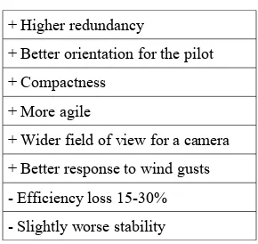
The frame consists of carbon tubes and glass fiber base plates. The landing gear is also made from carbon fiber using the vacuum bagging technique allowing safe and stabilize landing. Special attention is given to the camera mount. This very light servo-powered gyro-stabilized camera holder keeps the equipment in level during the flight. At the same time it dampens the vibrations from the engines. The camera can be remotely tilted to a desired angle along the horizontal axis. The system is powered by a high capacity Lithium Polymer (LiPo) batteries. Depending on the application and especially on the weight of the payload (1-1.5kg), the flight times varies from 10 to 15 minutes. The system weights with all equipment and additional sensors 4.8 kg. The on-board control segment is an embedded micro-PC with Atom processor connected to an Arduino autopilot. In its current configuration the PC governs the process of data acquisition and sets up the Ardupilot. A significant challenge associated with UAV is the safety. To enhance the safety either for people and public infrastructure on the ground or also for the micro-UAV itself, the helicopter is equipped with a parachute to face emergency situations. The parachute is currently deployed manually by the operator. The coaxial concept has its specific advantages and disadvantages. The Table 1 shows the basic characteristic of such a design.
Table 1. Main characteristic of a coaxial setup
+ Higher redundancy
+ Better orientation for the pilot + Compactness
+ More agile
+ Wider field of view for a camera
+ Better response to wind gusts - Efficiency loss 15-30% - Slightly worse stability
In manual mode the MAV helicopter can be operated by one pilot or as a cooperation between two operators: one pilot and a second person responsible for the data acquisition. The system structure is relatively universal as it can be (relatively easily) modified into a version with only four motors or the motors can be replaced with more powerful engines to increase the overall payload capacity.
2.2 Optical sensors
The chosen optical sensor on-board is the Sony Nex5 camera. The quality of this mirror-less camera is comparable with a SLR camera despite being considerably smaller (only 111x59x38 mm) and lighter (400g). These properties make it highly suitable for UAV platforms. The camera is equipped with a 16 mm fixed Sony lens, which has a very good optical quality and offers sufficient stability of the interior parameters within each mission. The camera is modified for better performance and integration into an UAV system. The on-board video processing segment procures a digital to analog conversion, video streaming and on-screen-display information of the current camera state as well as the telemetry data from the autopilot. The servo signal emitter is added to trigger IR diode shutter and the custom hardware modification eliminates existing shutter lag and enable precise time synchronization with other navigation components. These modifications together with the external power supply convert this low-cost camera to a serious photogrammetric tool. processing. The position of the UAV is processed as a post-processing, however, it is in its current state ready for RTK solution and for further integration with the embedded PC and INS.
2.4 Inertial
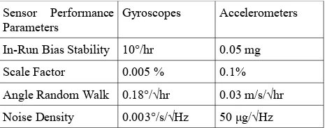
Within a scope of this study we employ the in-house developed FPGA-board called Gecko4Nav comprising of four MEMS-IMU chips, all precisely synchronized to the GPS time-reference (Kluter, 2012). The Gecko4Nav contains two main components. The FPGA board handling the synchronization and data flow is connected to the state-of-the-art custom sensor board, equipped with various types of sensors. The main components are four NavChips IMUs that are software-combined to a Redundant IMU (R-IMU). The manufactured-stated performance for each type of sensor is depicted in Table 2 (in total there are 16 of each type). The acquisition and control of the measurements is performed by the on-board firmware which governs also the IMU sampling frequency. The latter can be selected by the user in the range from 250-500 Hz. Dynamics encountered when the platform is in motion influence the behavior of sensor errors. More specifically, it varies its noise level in time. Although such variations are not known a priori, the system noise-level can be estimated on board thanks to multiple inertial sensors that are experiencing the same conditions. Following the R-IMUs configuration improves the navigation performance on several levels (Waegli et al., 2010). First, it allows to estimate the level of sensor noise directly from the data and provide a better view on the reality. The noise level of the overall system can be reduced by
weighted combinations. Additionally, it may be also mitigated directly in the navigation filter. Second, defective sensors can be detected and isolated via Fault Detection and Isolation procedure (Guerrier et al., 2012) Finally, the overall performance of an R-IMU is superior to its individual inertial units.
Table 2. Stochastic Characteristic of Inertial Sensors (16 in total, before calibration via INS/GPS)
Precise time-tagging of the camera shutter precisely within the GPS time-scale is the prerequisite for annotating the acquired imagery with the position and attitude information derived from the on-board GNSS/R-IMU. After calibration, this allows to employ the concept of direct sensor orientation. In MAV, the common way of image synchronization with the position is through the correlation between image acquisition time (stored in EXIF file) and GPS log. This method is sufficient for the in-direct approach of sensor orientation where the exterior para-meters enter only during the image pre-selection and/or as an initial approximation in the bundle adjustment. As the precise knowledge of the EO parameters is mandatory for direct or in-tegrated sensor orientation a considerably more accurate method of synchronization had to be conceived.
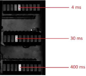
Several options are viable in terms of the change/modification of the triggering system or signalization of the shutter-opening. At the end we managed in eliminating the inaccuracy of the built-in IR shutter and attained the desired accuracy of image time-tagging.
Figure 2. The determination of camera lag using LED bar-graphs.
Table 3. Camera-lag statistics in a manual mode.
Number of samples 88
The Gecko4Nav allows operate up to four conventional IMUs (NavChip) on the same platform at the same time. The align-ment of the sampling to the same instance is a prerequisite for the before mentioned benefits of redundancy and performance alleviation. The Gecko4Nav features a synchronization module which uses the Pulse per Second (PPS) signal given by the GPS to synchronize the four IMUs. To provide a correct internal syn-chronization, the synchronization module acquires the PPS sig-nal and adjusts dynamically the drift within its crystal clock os-cillator. This method insures the continuity of the measurement procedure even if the PPS signal is lost. The IMUs synchroniza-tion was tested by placing the Gecko4Nav with the R-IMUs on top of a tactical grade inertial unit (iMAR-FSAS). The latter served as a reference, although only approximate alignment with respect to MEMS-IMUs was determined. The whole sys-tem was shaken along each axis and the dynamic responses were studied over the GPS-time. As shown on Figure 3, the four IMUs of the GECKO4nav are well synchronized between them and to the reference. a stochastic nature. These errors significantly influence the final navigation solution. Thus they need to be filtered using a plausible model. The process of model building is non-trivial at all. The following general error model can be formulated:
̂
l=Ml⋅(Sl⋅l+bl)+wl
where ̂l represents the estimated measurement, l the
nominal observation and Ml the misalignment matrix. The diagonal Sl contains the scale factors, bl is the bias and
wl the measurement random errors.
3.4 Random Errors without Bias
Often the Allan variance is used to determine the different type of random processes present in the signal. In general, with the Allan variance only five processes are considered: quantization noise, white noise, bias instability, random walk, and the ran-dom rate ramp. This method is only well defined for these few types of processes and it is not clear how inferences on the para-meters of these different processes can be made with this ap-proach. Thus the Allan variance is only used to build the model type, while it parameters are estimated using the approach of Generalized Method of Wavelet Moments (Stebler et al., 2012). The model comprises of a mixture of several Gauss-Markov processes with white-noise. The GMWM is used to estimate their parameters (i.e. the variances and correlation times). The estimation method is based on matching the empirical and mod-el-based wavelet variance. The GMWM is able to handle com-plex error models for which other techniques as the Allan vari-ance or EM algorithm fails or do not converge.
3.5 Deterministic parts
A multi-position calibration was used to estimate the deterministic errors such as the constant bias, the scale-factor and the non-orthogonality. This method does not require any special mounting. It uses the combined three-axis effect of the local gravity and earth rotation to build the references signals needed for calibration. The sensors do not have to be aligned to the local level frame. But it is necessary to have a redundant number of IMU rotations to estimate the errors by using a least-square adjustment knowing that in static conditions following constrains can be imposed:
with gx , y , z the acceleration measured along one axis, g
R-IMUs (i.e. synthetic, extended or constrained). The choice of the integration strategy is mainly guided by the a priori knowledge of the relative geometry between the individual IMUs (i.e. calibration vs. mission).
4. CASE STUDY
To evaluate the previously-described development and factually validate existing integration of all components, several field tests were done. Each test was performed for a specifically given task including image quality test, targets recognition, camera calibration and synchronization of all components. However, the case study describes only the precision of the direct positioning. The integration of IMU is not a subject of the following testings and will be presented separately.
4.1 Calibration field
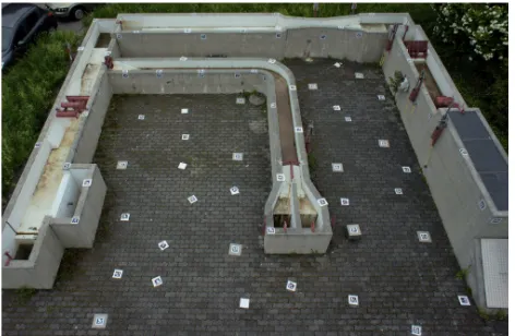
For the purpose of this study, we developed a calibration field. It is approximately 8x8 m large with spatial differences up to 2 m, Fig 4. Eighty digitally coded targets were placed regularly across the field into the grid. Seven targets were precisely determined with sub-cm accuracy using long-term GPS observations and served as control/check points. In such a set up we obtained high redundancy and excellent distribution of measurements across the image plane. The estimation of the targets-center in the image space was achieved by adopting the methodology commonly used by the augmented reality research community. Specifically, we have utilized the open-source ARToolKitPlus software library (Wagner and Schmalstieg, 2007) to perform automatic target recognition. We employed a BCH ARTag marker set due to its high marker library size, near-zero false positive identification rate as well as good centering accuracy which was reported to be 1/10 to 1/20 of a pixel (Fiala, 2010). The image measurements were automatically evaluated by C++ based scripts employing ARToolKitPlus and OpenCV libraries.
Figure 4 . Calibration field
As the calibration field is situated in a relatively dense urban environment the quality of the GPS signal reception suffered from the limited visibility to the sky and thus the relatively poorer geometry which influenced mostly the vertical precision. At the same time we have observed small interferences with the GPS signal that resulted in somewhat lower SNR and therefore lower than expected measured accuracy.
4.2 System calibration
The non-planar design of the target field as well as the variation of the angle of convergence and height above the target field decreases the correlation between the IO/EO parameters. Such flight was designed to determine mainly the lens distortions that are considered to be stable in time (i.e. across several missions).
4.3 Integrated sensor orientation
The performance of the proposed processing chain was evaluated during a separate flight where a set of 46 images was taken. All images were taken from different angles and all were centered to the calibration field. The UAV was controlled manually and the altitude during the flight was oscillating around 8 meters above the ground.
As it was mentioned in the section 1.3, the key factor for the comparison in the relative orientation between the camera, INS and GPS stays unmodified. This was achieved by hard mounting the GPS antenna and INS to the camera gimbal. Even during the flight, the rigidity of the mount guarantees to maintain the stability of the relative position.
The processing pipeline was following that of classical airborne image processing with assisted carrier-phase differential GPS. After the image acquisition, the custom program was executed to obtain the image measurements which were subsequently fed into a bundle adjustment (Bingo) together with the estimates of camera positions. The later were obtained by interpolating between the 10Hz GNSS solutions of carrier-phase differential results obtained by a professional software package. The custom scripts in Matlab carried out the assignment of images to the events exported from the receiver. The integrated orientation was performed using one target as a ground control point while the other targets served as check points.
The lever arm was measured with a caliper and results were compared with that estimated via the bundle adjustment where this value was presented as an additional parameter. Table 4 shows these values.
Table 4. Measured vs. estimated Lever Arm
Lever Arm Measured [cm] Estimated by Bingo [cm]
Ex 5.5 5.6
Ey 1.0 0.1
Ez 19.5 19.4
Table 5. Summary of integrated - sensor orientation (AT+GPS+1 GCP)
X [m] Y [m] Z [m] no. Airborne GPS accuracy 0.016 0.016 0.037 46 Photo positions
RMS (GPS-AT)
0.017 0.025 0.024 46
Control point 0.000 0.026 0.002 1
Check points RMS 0.036 0.022 0.019 6
The outcomes from the bundle adjustment confirmed the correctness of the preceding development in terms of camera/GNSS integration. The characteristics of residuals are presented in Figure 5 where deviations in position are depicted as points representing the difference between measured position and estimated by bundle adjustment. We can see, that the residuals are not correlated with respect to the flying speed. There are several outliers, however, most of the observations lies within the interval given by the predicted incertitude of the measured EO parameters. This confirms the sufficient elimination of the camera lag and precise synchronization with GPS. Yet another field test with rather higher flying speed has to be done to fully proof the correctness of the sensor implementation. In spite of the satisfying result from the adjustment, where the RMS in position differences on check points does not exceed 4.6 cm, there is still possible improvement and <3cm level accuracy in real-time localization will be attainable. The Table 5 summarizes the obtained mapping accuracy with 1 GCP. The precision of direct positioning matches expectations and corresponds to the accuracy of kinematic CP-DGPS. Despite that improvement can be still carried out. A part of the position error can be assigned to bad GPS signal, in particular, the higher than normal incertitude in height measurement.
5. CONCLUSION AND PERSPECTIVES
This research aimed in proposing and investigating novel approach in data acquisition with MAV. The most challenging part which was unequivocally the sensor integration and synchronization on the relative small and low cost UAV system was accomplished. A new drone was constructed based on open-source autopilot and imaging and navigation sensors were integrated on a gimbaled platform. This method isolates the measuring devices from vibrations and guarantees maintaining stable orientation between them. A small case study was performed to verify the synchronization and quality of the EO in terms of absolute positioning. The latter is at 2-5 cm level which corresponds to kinematic CP-DGPS. The method of integrated sensor orientation allows performing mapping with cm-level accuracy without or with one GPC.
REFERENCES
Bäumker, M., Przybilla, H.-J., 2011. Investigation on the accuracy of the navigation data of unmanned aerial vehicles using example of the system Mikrokopter, Vol. XXXVIII-1/C22 UAV-g 2011, Conference on Unmanned Aerial Vehicle in Geomatics, Zurich, Switzerland.
Blaha, M., Eisenbeiss, H., Grimm, D., Limpach, P., 2011. Direct georeferencing of UAVs, Vol. XXXVIII-1/C22 UAV-g 2011, Conference on Unmanned Aerial Vehicle in Geomatics, Zurich, Switzerland.
Colomina, I. Fritsch, D., 2007 From off-line to on-line geocoding: the evolution of sensor orientation Photogrammetric Week, Wichmann, 173-183.
Colomina, I., 2012. UAV for geomatic applications: The challenges, Lausanne.
Eugster, H. and Nebiker, S., 2008. Uav-based augmented monitoring - real-time georeferencing and integration of video imagery with virtual globes. The International Archives of the Photogrammetry, Remote Sensing and Spatial Information Sciences, ISPRS Congress, Beijing, China, XXXVII. Part B1, 1229-1236.
Fiala, M., 2010. Designing highly reliable fiducial markers. IEEE Transactions on Pattern Analysis and Machine Intelligence 32(7), pp. 1317–1324.
Guerrier, S., A. Waegli, J. Skaloud and M.-P. Victoria-Feser, 2012. Fault Detection and Isolation in Multiple MEMS-IMUs Configurations, in Ieee Transactions On Aerospace And Electronic Systems, vol. 48, p. 2015-2031.
Javad, 2013. Javad TR-G3T Datasheet. URL: www.javad.com/downloads/javadgnss/sheets/
TR-G3T_Rev.5_Datasheet.pdf.
Jon, J., Koska, B., Pospisil, J., 2013. Autonomous Airship Equipped with Multi-Sensor Mapping Platform," ISPRS - International Archives of the Photogrammetry, Remote Sensing and Spatial Information Sciences XL-5/W1, 119-124.
Kluter, T., 2012. GECKO4NAV Technical Reference Manual Revision 1.0.
Mostafa, M., Hutton, J., Reid, B., 2001. GPS/IMU products – the Applanix approach, Wichmann Verlag, Heldelberg.
Pfeifer, N., Glira, P., Briese, Ch., 2012. Direct georeferencing with on board navigation components of light weight UAV platforms, Volume XXXIX-B7, 2012 XXII ISPRS Congress, 2012, Melbourne, Australia.
Schwarz, K. P., Chapman, M., Cannon, M. & Gong, P., 1993. An integrated INS/GPS approach to the georeferencing of remotely sensed data Photogrammetric Engineering and Remote Sensing, 59(11), 1167-1674.
Skaloud, J., Cramer, M. & Schwarz, K. P., 1996. Exterior orientation by direct measurements of camera position and attitude International Archives of Photogrammetry, Remote Sensing and Spatial Information Sciences, 31, 125-130.
Skaloud, J., 1999. Optimizing Georeferencing of Airborne Survey Systems by INS/DGPS. PhD thesis, University of Calgary.
Skaloud, J., 1999. Problems in Direct-Georeferencing by INS/DGPS in the Airborne Environment, ISPRS, Workshop on 'Direct versus indirect methods of sensor orientation', Commission III, WG III/1, Barcelona, Spain.
Stebler, Y., Guerrier, S., Skaloud, J., Victoria-Feser, M.-P., 2012. A Framework for Inertial Sensor Calibration Using Complex Stochastic Error Models. ION/IEEE PLANS, Session A5, Myrtle Beach, SC, USA, IEEE-ION Position Location and Navigation Symposium.
Stebler, Y., Skaloud, J., 2013. Modeling and Processing Approaches for Integrated Inertial Navigation. EPFL, Lausanne.
Syed, Z. F., Aggarwal, P., Goodall, C., Niu, X., El-Sheimy, N. 2007. A newmulti-position calibration method for mems inertial navigation systems, Measurement Science and Technology, vol. 18, pp. 1897 –1907.
Wagner, D. and Schmalstieg, D., 2007. ARToolKitPlus for Pose Tracking on Mobile Devices. In: M. Grabner and H. Grabner (eds), Computer Vision Winter Workshop.
Wäegli, A., Skaloud, J., Guerrier, S., Parés. M. E, Colomina, I., 2010, Noise reduction and estimation in multiple micro-elecro-mechanical inertial system, Measurement Science and Technology (ISSN: 0957-0233), vol 21, p. 065201 (11p.)