Open Geospatial Consortium
35 Main Street, Suite 5Wayland, MA 01778 Telephone: +1-508-655-5858
Facsimile: +1-508-655-2237 Editor:
Telephone: +1-703-830-6516 Facsimile: +1-703-830-7096 [email protected]
The OpenGIS® Abstract Specification
Topic 16: Image Coordinate Transformation
Services
Version 6
Copyright © 1999-2000, Open Geospatial Consortium, Inc.
This document does not represent a commitment to implement any portion of this specification in any company’s products.
OGC’s Legal, IPR and Copyright Statements are found at http://www.opengeospatial.org/about/?page=ipr&view=ipr NOTICE
Permission to use, copy, and distribute this document in any medium for any purpose and without fee or royalty is hereby granted, provided that you include the above list of copyright holders and the entire text of this NOTICE. We request that authorship attribution be provided in any software, documents, or other items or products that you create pursuant to the implementation of the contents of this document, or any portion thereof.
No right to create modifications or derivatives of OGC documents is granted pursuant to this license. However, if additional requirements (as documented in the Copyright FAQ at
http://www.opengeospatial.org/about/?page=ipr&view=ipr_faq) are satisfied, the right to create modifications or derivatives is sometimes granted by the OGC to individuals complying with those requirements.
THIS DOCUMENT IS PROVIDED "AS IS," AND COPYRIGHT HOLDERS MAKE NO REPRESENTATIONS OR WARRANTIES, EXPRESS OR IMPLIED, INCLUDING, BUT NOT LIMITED TO, WARRANTIES OF
MERCHANTABILITY, FITNESS FOR A PARTICULAR PURPOSE, NON-INFRINGEMENT, OR TITLE; THAT THE CONTENTS OF THE DOCUMENT ARE SUITABLE FOR ANY PURPOSE; NOR THAT THE
IMPLEMENTATION OF SUCH CONTENTS WILL NOT INFRINGE ANY THIRD PARTY PATENTS, COPYRIGHTS, TRADEMARKS OR OTHER RIGHTS.
COPYRIGHT HOLDERS WILL NOT BE LIABLE FOR ANY DIRECT, INDIRECT, SPECIAL OR
CONSEQUENTIAL DAMAGES ARISING OUT OF ANY USE OF THE DOCUMENT OR THE PERFORMANCE OR IMPLEMENTATION OF THE CONTENTS THEREOF.
The name and trademarks of copyright holders may NOT be used in advertising or publicity pertaining to this document or its contents without specific, written prior permission. Title to copyright in this document will at all times remain with copyright holders.
RESTRICTED RIGHTS LEGEND. Use, duplication, or disclosure by government is subject to restrictions as set forth in subdivision (c)(1)(ii) of the Right in Technical Data and Computer Software Clause at DFARS 252.227.7013
Revision History
Date Description
24 February 1999 New topic volume from project document 99-002r2.
30 March 1999 Update to use new document template following guidance of change proposal 99-010 w/ friendly amendments to remove Section 1 boilerplate from individual topic volumes, approved 9 February 1999.
22 June 1999 Update following sections with changes from change proposal 99-030r2 (w/ friendly changes), approved at April 1999 TC meeting: Sections 4.1.6 through 4.1.27, 4.3.5, 4.3.6, 4.3.7, 4.4.5, 4.4.6, 4.4.7, 4.5, 5 and 6.
Table of Contents
1. Introduction... 1
1.1. The Abstract Specification ...1
1.2. Introduction to Image Coordinate Transformation Services...1
1.3. References for Section 1...1
2. Background for Image Coordinate Transformation Services ... 2
2.1. Image Coordinates ...2
2.2. Ground Coordinates...2
2.3. Position Accuracy ...2
2.4. Corresponding Image and Ground Points ...2
2.5. Image Geometry Models...3
2.6. Multiple Image Versions...4
2.7. Orthorectified Images ...5
2.8. Multiple Ground Coordinate Systems...5
2.9. Similarities to Ground Coordinate Transformations ...5
2.10. Standardization of Image Geometry Models ...6
2.10.1. Multiple Image Geometry Models...6
2.10.2. Standard Interfaces to Image Geometry Models ...6
2.10.3. Standard Image Geometry Models...7
2.10.4. OGC Standardization of Image Geometry Models...7
2.10.5. Proprietary Image Geometry Models...8
3. Essential Model for Image Coordinate Transformation Services .... 10
3.1. Image Coordinate Transformation Services...10
3.1.1. Image to Ground Coordinate Transformation ...10
3.1.2. Ground to Image Coordinate Transformation ...10
3.1.3. Output Coordinates Accuracy Data ...11
3.1.4. Handle Image Versions...12
3.1.5. Handle Multiple Ground Coordinate Reference Systems ...12
4. Abstract Specification for Image Coordinate Transformation
Services ... 15
4.1. Image Coordinate Transformation Services...15
4.1.1. Function ...15
4.1.2. Service Subtypes ...15
4.1.3. Result Data ...16
4.1.4. Needed Data...16
4.1.5. Discussion...16
4.1.6. Object Model...17
4.1.7. Class Name: StereoscopicImagesTransformation ...21
4.1.8. Class Name: PointStereoscopicImagesTransformation...22
4.1.9. Class Name: ListStereoscopicImagesTransformation ...22
4.1.10. Class: StereoscopicImagesTransformationWithAccuracy...23
4.1.12. Class Name: ImageCoordinateTransformation ...25
4.1.13. Class Name: PolynomialIMageTransformation ...25
4.1.14. Class Name: ImageRectification ...26
4.1.15. Class Name: ImageGeometryTransformation...26
4.1.16. Class Name: GroundShape...26
4.1.17. Class Name: ElevationSurface ...27
4.1.18. Class Name: ElevationModel...27
4.1.19. Class Name: ShapeModel ...28
4.1.20. Class Name: CoordinateTransformation ...28
4.1.21. Class Name: PointTransformation ...29
4.1.22. Class Name: ListTransformation...30
4.1.23. Class Name: TransformationWithAccuracy ...30
4.1.24. Class Name: ConcatenatedTransformation ...31
4.1.25. Class Name: TransformationStep...31
4.1.26. Class Name: MathTransform ...32
4.1.27. Class Name: Parameter...33
4.2. Imaging Time Determination Service...33
4.2.1. Function ...33
4.3. Image Geometry Model Conversion Services...35
4.3.1. Function ...35
4.3.2. Service Subtypes ...35
4.3.3. Result Data ...35
4.3.4. Needed Data...36
4.3.5. Object Model...36
4.3.6. Class Name: ImageGeometryFitting ...37
4.3.7. Class Name: ImageSupportDataConversion...38
4.4. Accuracy Conversion Services ...39
4.4.1. Function ...39
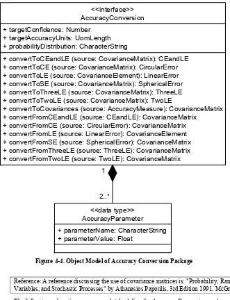
4.4.7. Class Name: AccuracyParameter ...42
4.5. Package Dependencies ...43
5. Well Known Structures... 44
5.1. Ground Position Coordinates...45
5.2. Image Position Coordinates...45
5.3. Ground SRS Definition ...45
5.4. Image SRS Definition ...45
5.5. Position Accuracy Estimates ...46
5.5.1. Covariance Matrix Data Structures...
Error! Bookmark not defined.
5.6. Elevation Data...47
5.7. Elevation Accuracy Estimates ...47
5.8. Desired Image Section...48
5.10. Selection of Service Operation...48
5.11. Other Inputs and Outputs...
Error! Bookmark not defined.
5.12. Accuracy Conversion Parameters ...
Error! Bookmark not defined.
6. Future Work... 50
7. Appendix A. Acronyms and Glossary ... 51
7.1. Acronyms ...51
7.2. Definitions ...51
1. Introduction
1.1. The Abstract Specification
The purpose of the Abstract Specification is to create and document a conceptual model sufficient enough to allow for the creation of Implementation Specifications. The Abstract Specification consists of two models derived from the Syntropy object analysis and design methodology [1]. The first and simpler model is called the Essential Model and its purpose is to establish the conceptual linkage of the software or system design to the real world. The Essential Model is a description of how the world works (or should work).
The second model, the meat of the Abstract Specification, is the Abstract Model that defines the eventual software system in an implementation neutral manner. The Abstract Model is a description of how software should work. The Abstract Model represents a compromise between the paradigms of the intended target implementation environments.
The Abstract Specification is organized into separate topic volumes in order to manage the complexity of the subject matter and to assist parallel development of work items by different Working Groups of the OGC Technical Committee. The topics are, in reality, dependent upon one another each one begging to be written first. Each topic must be read in the context of the entire Abstract Specification.
The topic volumes are not all written at the same level of detail. Some are mature, and are the basis for Requests For Proposal (RFP). Others are immature, and require additional specification before RFPs can be issued. The level of maturity of a topic reflects the level of understanding and discussion occurring within the Technical Committee. Refer to the OGC Technical Committee Policies and Procedures [2] and Technology Development Process [3] documents for more information on the OGC OpenGIS™ standards development process.
Refer to Topic Volume 0: Abstract Specification Overview [4] for an introduction to all of the topic volumes comprising the Abstract Specification and for editorial guidance, rules and etiquette for authors (and readers) of OGC specifications.
1.2. Introduction to Image Coordinate Transformation Services
This topic volume is the portion of the OpenGIS™ Abstract Specification that covers image coordinate conversion services. That is, this part of the abstract specification describes services for transforming image position coordinates, to and from ground position coordinates. These services might alternately be called “Image Geometry Model Services.”
1.3. References for Section 1
[1] Cook, Steve, and John Daniels, Designing Objects Systems: Object-Oriented Modeling with Syntropy, Prentice Hall, New York, 1994, xx + 389 pp.
[2] Open GIS Consortium, 1997. OGC Technical Committee Policies and Procedures, Wayland, Massachusetts. Available via the WWW as <http://www.opengis.org/techno/development.htm>. [3] Open GIS Consortium, 1997. The OGC Technical Committee Technology Development Process,
Wayland, Massachusetts. Available via the WWW as
<http://www.opengis.org/techno/development.htm>.
2. Background for Image Coordinate Transformation Services
This topic volume is the portion of the OpenGIS™ Abstract Specification that covers image coordinate conversion services. That is, this part of the abstract specification describes services for transforming image position coordinates to and from ground position coordinates. These services might alternately be called “Image Geometry Model Services.”This section provides background information useful in understanding the Image Coordinate Transformation Services discussed in later sections.
2.1. Image Coordinates
The position of a point in an image is specified in two-dimensional (2-D) image coordinates. A point of interest may be either a real or virtual point. The material in this topic volume is currently limited to 2-D images; it could be expanded in the future to include 3-D images.
For a digital image, the 2-D image coordinates are usually specified in the row and column directions of image pixels. The reference point for these image coordinates is usually the corner pixel of the image where the pixel row and column indices are either (1, 1) or (0, 0). Alternately, the reference point for image coordinates could be the center pixel, when the number of pixels is an odd number in each axis. When the number of pixels is even in each axis, the reference point for image coordinates could be the middle of the four most-center pixels.
Image coordinates could be specified as integers, referring to pixel indices. However, image coordinates are usually specified as floating point numbers, to allow coordinates to represent positions with fractional pixel spacings. The center of the corner pixel is often considered to have coordinates (1, 1). Alternately, the outside corner of the corner pixel could be considered to have coordinates (0, 0).
For a film or hardcopy image, the 2-D image coordinates are usually specified in two orthogonal axes, which could be called x and y or u and v. Various reference points can be used, such as the “center” of the image. These image coordinates are often specified as floating point numbers, in units of millimeters.
2.2. Ground Coordinates
The position of a point in ground space is specified in three-dimensional (3-D) coordinates. This document uses the term ground coordinates; photogrammetry often uses the alternate term “object coordinates.” Again, a point of interest may be a real or virtual point.
For Image Coordinate Transformation Services, ground coordinates are almost always 3-D, since the position of a point in all three dimensions affects the image position corresponding to that point. These ground coordinates are specified in some Spatial Reference System (SRS), such as any SRS defined in Abstract Specification Topic 2.
2.3. Position Accuracy
These Image Coordinate Transformation Services assume that most image and ground coordinates have a relatively high precision or accuracy. Image coordinates might be known or desired with an accuracy between a few tens of pixel spacings and a few tenths of one pixel spacing. Ground coordinates might be known or desired with an accuracy between a few tens of meters and a few millimeters.
The numerical values of image and ground point coordinates always have limited accuracies. If the accuracy were truly unknown, the numerical value would have little practical value. If the accuracy is known, that accuracy should be communicated from the data producer to the data user, so that the data user can properly interpret and use the numerical value. Recording of position accuracy information is therefore required by the OpenGIS Abstract Specification, Topic 1: Feature Geometry, in Figure 2-1 and Section 2.2.1.3. Topic Volume 9 specifies in considerable detail the accuracy data mentioned only briefly elsewhere in the Abstract Specification.
2.4. Corresponding Image and Ground Points
specified in image coordinates in one image usually can correspond to an infinite number of ground position coordinates. In most imaging geometries, these ground positions all lie along one imaging ray.
Obviously, the corresponding image coordinates and horizontal ground coordinates will (almost always) have different reference points and scales. Furthermore, the shapes of objects will be different in image and horizontal ground coordinates. Straight lines in ground coordinates will rarely be perfectly straight in image coordinates. Parallel lines in horizontal ground coordinates will usually not be parallel in image coordinates. Similarly, evenly spaced points along a line will usually not be evenly spaced in image coordinates.
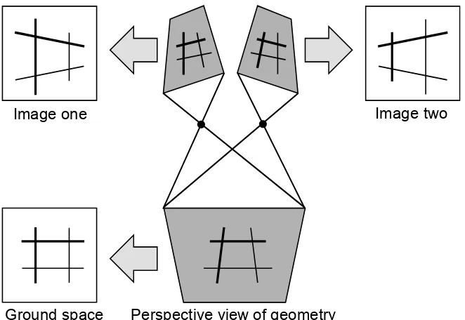
Some of the possible shape differences are indicated in the diagram of Figure 1. Down the center is a cartoon showing a horizontal rectangular feature on the ground with two images of that ground area. The bottom left square indicates how this feature appears in horizontal ground coordinates. The top-left and top-right squares indicate how this feature could appear in two different images. This figure assumes that the two images are tilted significantly from vertical, as is typical with convergent stereoscopic images. Of course, many real images would be tilted less, producing less distortion of the ground rectangle. However, there is usually some significant shape distortion in an image of a ground feature.
Image one
Image two
Perspective view of geometry
Ground space
Figure 1. Corresponding Ground and Image Shapes
When high accuracy is needed, image exploitation must consider various image sensor (or camera) non-idealities from a perfect frame (or pinhole) camera. These non-idealities often include lens distortion, atmospheric refraction, and earth curvature, all of which tend to change straight lines into (slightly) curved lines.
2.5. Image Geometry Models
To determine the correct image position of a ground point, an image geometry mathematical model is used. Such an image geometry model relates 3–D ground position coordinates to the
surface. For example, this additional data is often grid elevation data. Alternately, two or more stereoscopically overlapping images can be used, that show the same ground point viewed from different directions. In this case, the multiple image geometry mathematical models can be used, with the point coordinates in each image, to determine the corresponding 3–D ground position. (A single IFSAR image can be used to derive the corresponding 3–D ground position, because the gray value represents the distance from the camera to the ground point.)
An accurate image geometry model is more complex than a simple polynomial coordinate transformation, between ground coordinates and image coordinates. This document primarily considers high accuracy image geometry models for general images. Much simpler geometry models are adequate when low accuracy is sufficient, or for images that have been orthorectified. Also, much simpler geometry models can provide medium horizontal accuracy for rectified or nearly-vertical images, when the imaged ground is relatively flat. Many different high accuracy image geometry models can be used, as summarized in Topic Volume 7: The Earth Imagery Case [1].
There are multiple possible geometry models for an image, with different properties. For example, a rigorous geometry model can be accurately adjusted, but has high computation requirements. On the other hand, a non-rigorous or “approximate” geometry model has lesser computation
requirements, but cannot be accurately adjusted. Conversion from a rigorous geometry model to a corresponding approximate geometry model for the same image is then sometimes required. However, conversion from an approximate geometry model to a rigorous geometry model is usually not possible or practical.
The term “approximate” image geometry model is used here as a synonym for a “non-rigorous” image geometry model. However, many degrees of accuracy are possible when considering the position errors introduced by the approximation, from large position errors through no detectable position errors. For example, the “Universal Approximate Image Geometry Model” described in Section 6.5 of Topic 7 can be fitted to almost all rigorous models with no significant position error. Similarly, the “Grid Interpolation Image Geometry Model” described in Section 6.3 of Topic 7 can approximate a rigorous model with no significant position errors, if enough grid points are used. An approximate image geometry model has often been called a “real-time” geometry model, and that is the term now used in Topic Volume 7: The Earth Imagery Case [1]. The need for a fast “real-time” geometry model is decreasing, as computer speeds increase. However, a fast geometry model is still useful in some situations (such as generating complex feature graphics overlaid on an image). On the other hand, an “approximate” image geometry model can be needed or useful for other purposes, such as ignorance or inaccessibility of a rigorous geometry model.
Note: Although Abstract Specification Topic 7 defines both rigorous and “real-time” or approximate image geometry models, Topic 7 currently includes examples of only approximate image geometry models. It would be useful to add examples of rigorous image geometry models to Topic 7, but no volunteer has yet proposed a description of any rigorous model.
2.6. Multiple Image Versions
Multiple versions of the same original image with different image coordinates will usually exist, simultaneously and/or sequentially. Image exploitation can use any one of these image versions, not always the original image. However, there is usually only one basic image geometry model recorded for one image, usually for the original image.
The various versions of an image can have image coordinates that differ from the original image coordinates by:
1. Different origin and range of pixel indices, as a result of copying only a rectangular section of the original image.
2. Different pixel spacings, as a result of generating reduced resolution versions of the original image and/or of changing the apparent image magnification or demagnification. Reduced resolution versions often have pixel spacings that are powers of two times the original pixel spacing. Magnified or demagnified versions can have pixel spacings that are any number times the original pixel spacing. (For example, the magnification factor could be NN.NNN, where N is any decimal digit.)
4. Affine (first order polynomial) transformation of image coordinates, as a result of affine warping of the image pixels. Such an affine coordinate transformation might use the equations:
u
=
K1
+
K2 * x
+
K3 * y
v
=
K4
+
K5 * x
+
K6 * y
Where:
x, y = original image coordinate u, v = transformed image coordinates Kn = transformation parameter
(Note that this transformation includes, but is more general than, items 1 through 3 listed above.)
5. Image rectification, by mathematical projection from the actual imaging surface through the image perspective point onto another smooth surface. The second smooth surface is often a plane, selected to approximate the average surface of the earth in the region covered by the image. This rectification could include corrections for imaging non-idealities such as lens distortion and atmospheric refraction. (However, this rectification does not include corrections for an irregular shape of the ground, as represented by elevation data. Inclusion of corrections for an irregular ground surface is normally termed orthorectification or differential
rectification, not rectification.) 6. Combination of the above
Some image versions are produced directly from the original image. Other image versions are produced from previously produced image versions. In this case, the image coordinates of the new image version might or might not be represented by a simple coordinate transformation from or to the original image coordinates.
2.7. Orthorectified Images
These image coordinate transformation services do not directly apply to orthorectified images. In an orthorectified image or orthophoto, the effects of the imaging geometry have been removed to the maximum practical extent. Orthorectified image coordinates are thus simply scaled and offset ground coordinates, using a selected ground coordinate reference system. Orthorectified image coordinates could also be rotated ground coordinates, but this is rare. On the other hand, image coordinate transformation services are needed to produce an orthorectified image.
2.8. Multiple Ground Coordinate Systems
Exploitation of an image can be into several different ground coordinate Spatial Reference Systems (SRSs), usually sequentially or perhaps simultaneously. However, the basic image geometry model is normally available and implemented relative to one specific ground SRS. This ground SRS of the image model may not be the only or primary ground SRS needed in exploiting this image.
Therefore, ground coordinate transformation services will often be needed, between the ground SRS used in the image geometry model and the one(s) desired for data from the exploited image, or data used in exploiting the image. These ground coordinate transformation services, and their interfaces, are being specified separately, by the Coordinate Transformation (CT) Working Group (WG) of the OGC. However, these ground coordinate transformation services need to be closely integrated with the image coordinate transformation services, and their interfaces, to effectively support image exploitation.
2.9. Similarities to Ground Coordinate Transformations
Image coordinate transformations have many commonalties with ground coordinate
transformations, as discussed in Abstract Specification Topic 2. These commonalties include: 1. Use similar interface data, including position coordinates and metadata about these
coordinates
4. Need to use a common software framework, to simplify use of many different coordinate transformations
5. Need metadata about the coordinate transformations
6. Use ground coordinate transformations within image coordinate transformations However, image coordinate transformations have certain differences from ground coordinate transformations. These differences include:
1. Decrease or increase the number of position coordinate dimensions, by an image coordinate transformation
2. Need many different image coordinate transformations for different image geometry types and different image versions
3. Less standardization now exists of image coordinate transformations, especially of image geometry models
4. Production (and use) of accuracy data is more important, because the errors are often more significant
2.10.
Standardization of Image Geometry Models
A number of different image geometry models are needed, for exploiting different image types under different conditions. Multiple different image geometry models should thus be standardized by the OGC (in the long term). However, some proprietary image geometry models are expected to exist, and not be standardized. Implementations of all these image geometry models should use one standardized Applications Programming Interface (API) for each distributed computing
environment.
2.10.1. Multiple Image Geometry Models
Multiple different image geometry models are needed, for exploiting different image types under different conditions. There are many different types of imaging (or camera) geometries, including frame, panoramic, pushbroom, whiskbroom, Synthetic Aperture Radar (SAR), Interferometric SAR (IFSAR), X-Ray, and (laser or radar) altimetry profiles. Many of these imaging geometries have multiple subtypes, for example, multiple small images acquired simultaneously. These image geometries are sufficiently different that somewhat different rigorous image geometry models are required. Furthermore, different cameras of the same basic geometry can require different rigorous image geometry models.
Technical Question: How are IFSAR and X-Ray image geometries different from other geometry types?
Different image exploitation conditions can also need different image geometry models. For example, an approximate geometry model may be required for real-time use, which need not be rigorous. Fitted general image geometry models may be needed for use with multiple types of basic image geometries, where these general-purpose image geometry models cannot be rigorous. Multiple different image geometry models need not be completely different. Multiple image geometry models can use common submodels where appropriate. For example, common submodels might be used for corrections that are common to multiple rigorous image geometry models, such as atmospheric refraction and lens distortion.
2.10.2. Standard Interfaces to Image Geometry Models
A variety of types of partial derivative are of potential interest, including: 1. Partial derivatives of image coordinates with respect to ground coordinates 2. Partial derivatives of ground coordinates with respect to image coordinates
3. Partial derivatives of image and ground coordinates with respect to (adjustable) image geometry model parameter values
Author’s Note: I assume that such a standard image geometry model API is practical and commercially viable. The technical feasibility of such an API has been largely proven, at least by work done by BAE SYSTEMS (formerly GDE Systems, Inc.) Their SOCET SET® commercial photogrammetric software has used a standard image geometry model API for several years, using the same API for about 30 different image geometry models.
2.10.3. Standard Image Geometry Models
When inter-operation of software from multiple software producers is needed, standard image geometry models need to be specified and used. Such inter-operating software includes the software that produces a specific image geometry model for each image, and the software that uses this image geometry model for image coordinate transformation. In many cases, multiple different software packages must use the same image geometry model, in different image exploitation environments and/or to meet different image exploitation needs. In other cases, multiple different software packages must produce the same type of image geometry model, for use by the same image coordinate transformation software package(s).
A standard image geometry model must specify the form and format in which image geometry data is transferred between different software packages. A standard image geometry model must also specify the semantics of the data transferred. These semantics will often include a set of equations that specify how the transferred data must be interpreted for image coordinate transformation. Although the image coordinate transformation software might directly implement the specified equations, that software will often implement a different but equivalent set of computations. Such equivalent computations will be designed to optimize some quality of the software, such as computation speed.
In this context, an “image geometry model”, together with the values for all the parameters used in that model, completely defines the correct relationship between all possible image positions and the corresponding ground positions. Usually one 2-D image position corresponds to many possible 3-D ground positions.
Such an image geometry model is not a computation algorithm. However, a computer
implementation of an image geometry model must use at least one algorithm. One image geometry model can (almost) always be implemented using any of several alternative algorithms. Indeed, different algorithms are normally used for each coordinate transformation direction between image and ground coordinates.
A common way to specify an image geometry model is by giving algebraic equations that could be used to calculate image coordinates from ground coordinates, or vice-versa. Direct implementation of those equations in any programming language comprises one possible algorithm for
implementing coordinate transformation in that direction using that image geometry model. However, use of such equations to specify an image geometry model does not require use of the directly corresponding algorithm.
2.10.4. OGC Standardization of Image Geometry Models
The OGC should standardize the image geometry models that are expected to have widespread use by interoperable software. This means that the OGC should plan to standardize multiple different image geometry models, with the number of standardized models probably increasing over time. In standardizing an image geometry model, the OGC should not standardize an algorithm for implementing that model. The OGC should allow a standard interface conforming service implementation to use any algorithm that always produces equivalent results.
In defining standard image geometry models and submodels, the OGC probably should cooperate with the International Society of Photogrammetry and Remote Sensing (ISPRS). Several ISPRS commissions are doing related work, including:
Commission I: Sensors, Platforms and Imagery; Chair: G. Joseph (India)
Commission II: Systems for Data Processing, Analysis & Presentation; Chair: I. Dowman Commission III: Theory and Algorithms; Chair: T. Schenk (USA)
Author’s Note: The following text discusses several important questions about how the OGC should proceed toward standardizing image geometry models and geometry model data formats. For each of several needed technical decisions, the OGC TC might make the decision, before issuing the relevant RFP. Alternately, the OGC TC might ask teams responding to the relevant RFP to recommend each decision. Similarly, the OGC TC might let teams submitting RFCs recommend each decision. The OGC TC would then accept the recommended decision when it approves an Implementation Specification using that decision. This Section implies Arliss Whiteside’s opinion on many of these needed decisions.
The set of image geometry models (or model types) to be standardized by the OGC might be completely selected by the OGC Technical Committee (TC). Probably better, specific image geometry models to be standardized might be proposed by vendors, and adopted by the OGC. The types of image geometry submodels to be standardized by the OGC might be more completely selected by the OGC TC. These submodels might be organized into categories, such as geometric model (e.g. earth curvature, lens distortion, principal point of autocollimation) and physical model (e.g. atmospheric refraction, radar or laser properties).
The specific image geometry models and submodels standardized might be (largely) specified by the OGC TC (with the ISPRS), perhaps in the form of model equations. Probably better, specific image geometry models might be specified by vendors in response to RFPs or in RFCs. Similarly, the forms used to transfer image geometry model data might be specified by the OGC TC or proposed by vendors. The complete format details for transferring data for each image geometry model should be specified by vendors, in response to a RFP or in a RFC.
2.10.5. Proprietary Image Geometry Models
Although multiple image geometry models should be standardized by the OGC, there will probably also be proprietary image geometry models that are not standardized. These proprietary image geometry models will be used only when the geometry model implementation software need not be interoperable. Although complete image geometry models may be proprietary, submodels are more likely to be proprietary. For example, camera internal geometry models are more likely to be proprietary.
These proprietary image geometry models and/or submodels are likely to be used by vendors who want to protect the nature of their image geometry and/or image geometry model. For these proprietary models, encryption of the model geometry data and/or the implementation software might be used to further conceal the details of the image geometry model.
In order to be useful and used, software implementing the needed image coordinate transformation capabilities using a proprietary image geometry model or submodel probably must:
1. Be provided at no extra cost by the supplier of the images using the model, or by the supplier of geometry model parameter data for specific images, so there is no need for competition between suppliers
2. Be available for all important computing platforms (such as Windows and UNIX) 3. Include capabilities and interfaces for all types of geometry model adjustment needed for
image registration, if any such adjustment is needed. (These capabilities and interfaces for model adjustment could be designed to hide the specific nature of the model parameters being adjusted.)
geometry models. For example, the standardized APIs should allow vendors to tailor the accuracy, computation speed, and other properties of their proprietary model implementations.
To simplify use and implementation, such proprietary image coordinate transformation software might also be:
1. Coded in a programming language that can be executed in many computing environments (such as JAVA)
2. Available for automatic download when needed, over the Internet or other network (like JAVA Applets)
3. Essential Model for Image Coordinate Transformation Services
This section presents an essential model of Image Coordinate Transformation (ICT) Services, in the context of the use of these services within general image exploitation.3.1. Image Coordinate Transformation Services
3.1.1. Image to Ground Coordinate Transformation
When the image positions of one or more points are identified during image exploitation, the ICT Services should transform the image coordinates to the corresponding ground coordinates. The image positions might be either manually or automatically identified, outside the ICT Services. The transformation to ground coordinates might be manually initiated, but will often be automatically initiated by other image exploitation software, when it is in certain operating modes.
The ground coordinates of each point are normally saved or recorded, not the image coordinates. Either the 3-D ground coordinates or the 2-D horizontal ground coordinates might be saved, depending on the application. However, 3-D ground coordinates are usually computed. In many cases, the 3-D or 2-D ground coordinates are saved as vertices of a feature geometry, and the image exploitation services could be directly connected to a vector GIS.
3.1.1.1. Single or Monoscopic Image
When a single (or monoscopic) image is being exploited (for each point), the image coordinates of each point are identified in one image. In order to determine the corresponding ground coordinates, additional information is needed. In general, this additional information must specify the position and shape of the visible ground surface. Often, this additional information is one elevation value, specifying the elevation of a horizontal surface in which the corresponding ground point coordinates (are assumed to) lie. Alternately, an elevation coverage can be used, that defines the (approximate) elevation of visible points at all horizontal positions within a region. Other additional information could alternately be used, such as radar range or laser profiling data.
The elevation information to be used is usually selected before image positions are identified. The same elevation information is often used for a series of image positions, until new elevation information is selected.
3.1.1.2. Multiple or Stereoscopic Images
When multiple (or stereoscopic) images are being exploited, the image coordinates of each point are identified in two or more images. Images of the same ground point in different images are often referred to as conjugate points or homologue points. If these images view each ground point from different viewing directions, sufficient information is available (or derivable) to determine the corresponding 3-D ground coordinates. Stereoscopic images are two images collected from different positions in space, that cover a common region on the ground. However, more than two images can be used together, to produce more accurate ground coordinates or otherwise better extracted data.
3.1.2. Ground to Image Coordinate Transformation
When the ground positions of one or more points are to be used during image exploitation, the ICT Services should transform the ground coordinates to the corresponding image coordinates, in one or more images. The transformation to image coordinates might be manually initiated, but will often be automatically initiated by other image exploitation software, when it is in certain operating modes.
The ground positions of interest might be manually or automatically identified. The one or more images being exploited are often identified before the desired ground positions. These images are often the same for a series of ground positions, until new images are selected. Alternately, the images in which a ground position appears might be automatically determined, especially if selecting from a limited set of images previously identified.
extracted might be displayed or used by some automated process. There are many such automated image exploitation processes, including:
1. Image resampling to produce an orthorectified image 2. Automated image matching
(Note: Most persons not familiar with image exploitation assume that transforming image to ground coordinates is most frequently used. In practice, transforming ground to image coordinates is more frequently used, especially in stereoscopic image exploitation.)
3.1.3. Output Coordinates Accuracy Data
In addition to producing ground or image coordinates, the ICT Services should output data describing the position accuracy of these output coordinates. Position accuracy output data is not useful in all image exploitation operations, and may be rarely needed for image coordinates. However, accuracy data should be automatically produced whenever it is needed by the current image exploitation operation.
This accuracy data should take the form of position error statistical estimates. Absolute error estimates should be available for single points, relative to the defined coordinate SRS. Relative error estimates should be available for pairs of points. These error estimates should be in the form of covariance matrices, as defined and specified in Abstract Specification Topic 9: Quality. 3.1.3.1. Output Accuracy Determination
Error estimates for coordinates output from a transformation should represent the combination of all significant error sources (or error components). In general, three types of error sources need to be considered: input coordinate errors, transformation parameter errors, and transformation computation errors.
The input coordinates used by the transformation will often contain errors, which propagate to the output coordinates. Error estimates for the input coordinates can be propagated to the resulting output error estimates by using the partial derivatives of the individual output coordinates with respect to the individual input coordinates.
The transformation parameters used will often contain errors, which propagate to the output coordinates. Error estimates for the transformation parameters can be propagated to the resulting output error estimates by using the partial derivatives of the individual output coordinates with respect to the individual transformation parameters.
The transformation computations will sometimes introduce significant errors, at several steps in the computation, which propagate to the output coordinates. Typical computation errors can be propagated to the resulting output error estimates by using the partial derivatives of the individual output coordinates with respect to the internal quantities where errors are committed.
3.1.3.2. Input Coordinates Accuracy Data
In order to produce output coordinates accuracy data, the ICT Services will usually need similar accuracy data for the input coordinates. For image coordinates, this input accuracy data should reflect the estimated errors in determining the correct image position. In some cases, the proper image coordinates error estimates will be zero.
3.1.3.3. Coordinate Transformation Accuracy Data
To produce output coordinates position accuracy data, the ICT Services will also generally need accuracy data for the transformation performed. This transformation accuracy data might be for the transformation as a whole, or for the various parameters used in the transformation.
A transformation between ground and image coordinates will have non-zero errors, except for synthetic images. A coordinate transformation between two different image versions will often have zero error estimates, except for computation errors. A coordinate transformation between different ground SRSs will sometimes have significant errors. However, ground coordinate “conversions” will have zero error estimates, except for computation errors.
committed. Although very rare, some ground coordinates could have similar size errors from all other sources.
Data about the inherent accuracy of a coordinate transformation should be recorded as metadata for that transformation. Data about the computation error in an implementation of a coordinate transformation could be either internal data of the implementation or metadata about that implementation.
3.1.4. Handle Image Versions
The ICT Services should automatically handle image coordinates in any version of the original image that has been created and is being used in image exploitation. The selection or identification of any image must include identification of the particular image version being exploited.
3.1.5. Handle Multiple Ground Coordinate Reference Systems
The ICT Services should automatically handle ground coordinates in any desired ground coordinate Spatial Reference System (SRS). The desired ground SRS for data being extracted from an image must be selected or identified. This will often be done once, for an entire image exploitation session. The ground SRS for each group of existing ground coordinates being used in image exploitation also needs to be identified. Some of this data may be in the same ground SRS as data being extracted. Other existing data will be in other ground SRSs, and must have metadata that specifies its ground SRS.
3.2. Interface Subset Purposes
An image coordinate transformation service should support external interfaces having multiple interface subsets that are designed and used for different purposes. (Indeed, most OGC
standardized interfaces are likely to support multiple interface subsets designed for different uses.) These interface subsets for different purposes might be formally defined or not, and could overlap. Some interface subsets, with the associated service capabilities, will be optional and thus not provided by all service implementations.
Explicitly thinking about the possible interface subsets for different purposes appears useful in developing service interface abstract and implementation specifications. These interface subsets might be used by different actors, in one or multiple UML use cases. In some cases, different interface subsets will be used by different client software. In other cases, multiple interface subsets will be used by the same client software.
For an image coordinate transformation service, interface subsets should be designed to support several uses, including:
1. Performing image coordinate transformations, plus closely related computations 2. Importing the image support data needed to subsequently perform image coordinate
transformations
3. Service administration 4. Accuracy data conversion 5. Service metadata access
6. Adjustment of the current image coordinate transformation(s)
Of course, the initial interfaces standardized by the OGC might not include all of these interface subsets. The interface purpose subsets listed above are discussed in the following subsections.
3.2.1. Perform Coordinate Transformations
To separate usage and design concerns, this coordinate transformation interface subset assumes that the service has already been initialized and provided with all the (image) support data needed to perform these coordinate transformations. The interface subsets needed to do this are discussed below.
Because this is the most fundamental interface subset, almost all the interface operations defined later in the Abstract Model (see Sections 4.1.6 through 4.1.27) are in this interface subset.
3.2.2. Import Support Data
For image coordinate transformation services, the next critical interface subset purpose is importing the image support data that is required to subsequently perform image coordinate transformations. These interfaces are needed whenever separate software packages (or systems) produce and (later) use this image support data. This image support data includes all the information needed to define the correct relationship between corresponding image and ground coordinates. This interface subset probably should include interfaces for exporting the image support data for later use.
In many cases, the interface subset for importing image support data should be standardized by the OGC. Standardization is needed to allow interoperation between different software packages that may produce and use this image support data. Standardization is also needed to support
interoperation between different software packages that may need to perform coordinate transformations for the same images. Standardization is also desirable to allow any of multiple software packages (and systems) to produce image support data for use by (one or more) image coordinate transformation packages.
On the other hand, (complete) OGC standardization of an interface subset to import image support data may not be possible or not be needed for image support data whose contents are proprietary. To separate usage and design concerns, this import data interface subset may assume that the service has already been initialized. The interface subset needed to initialize the service is discussed below. Alternately, that interface subset might be intimately combined with this interface subset. The “Image Support Data Conversion” interface operations defined later in the Abstract Model (see Sections 4.3.6 and 4.3.7) are in this interface subset.
3.2.3. Administer Service
In general, one needed interface subset purpose is administration of the service implementation software. Such administration functions might include starting and stopping service software: (a) readiness to execute, (b) communication connection to client software, and/or (c) usage session by client software. Other possible administration functions include setting and checking service operation properties, such as quality of service and service options.
To separate usage and design concerns, this interface subset may be separate from all others. Alternately, this interface subset could be partially or fully combined with the interface subset for importing image support data (see previous section).
3.2.4. Convert Accuracy Data
For image coordinate transformations, one possible interface subset purpose is conversion of accuracy data between different forms. Such conversions may be needed by clients before or after exercising other image coordinate transformation functions.
To separate usage and design concerns, this interface subset may be separate from all others. Alternately, this interface subset could be partially or fully combined with another the interface subset.
The “Accuracy Transformations” interface operations defined later in the Abstract Model (see Section 4.4.6 and 4.4.7) are in this interface subset.
3.2.5. Access Service Metadata
describing the general accuracy of the transformation, plus the identification of the specific image version supported. Both metadata retrieval and modification might be supported by this interface subset.
No specific metadata access capabilities are currently defining in the Abstract Model (see Section 4), but are the subject of needed future work (see Section 6).
3.2.6. Adjust Image Coordinate Transformation
For more complex image exploitation, image coordinate transformation services can provide an interface subset that supports effective adjustment of the current image-ground transformation. These interfaces allow changing the current (approximate) image-ground transformation of one or more images to better match each other and other geospatial datasets. This can be done by changing some current image-ground transformation parameters, using the derived from the current positions of one or more points in two or more datasets.
The service interfaces used for this interface subset purpose are likely to include some of the interfaces used for other purposes, especially the interfaces that Perform Coordinate
4. Abstract Specification for Image Coordinate Transformation
Services
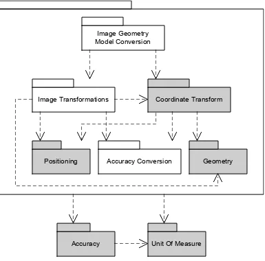
This section presents an abstract model of the Image Coordinate Transformation (ICT) Services. This abstract model of these services is divided into four parts, based on the similarity of the primary data produced and needed by each service part:
1. Image Coordinate Transformation Services. This primary part provides the basic image coordinate transformation services.
2. Imaging Time Determination Service. This expected future optional part provides access to imaging times.
3. Image Geometry Model Conversion Services. This optional part supports creating a new approximate image geometry model from an existing model.
4. Accuracy Conversion Services. This auxiliary part provides frequently-needed conversions of the form of accuracy data.
The following service descriptions do not describe the contents and formats of the “needed data” and “result data” of each service. The “needed data” could alternately be called inputs, and the “result data” could alternately be called outputs. The “needed data” and “result data” of multiple services are often identical or similar, so the possible contents and formats service of this data are discussed later in Section 5.
The image coordinate transformation services will often use and produce metadata about the coordinates that are manipulated. Metadata is the subject of the Metadata SIG and of Topic 11 of the Abstract Specification. To help define service interactions with metadata, the “needed data” and “result data” items listed are often annotated with “(is metadata for...)”.
4.1. Image Coordinate Transformation Services
4.1.1. Function
The Image Coordinate Transformation Services convert image position coordinates between different Spatial Reference Systems (SRSs). Some service operations may have operations that convert the positions of multiple points, not just one point at a time. An alternate name for these Image Coordinate Transformation Services would be “Image Geometry Model Services”.
4.1.2. Service Subtypes
The expected sub-types of Image Coordinate Transformation Services include, but are not necessarily limited to:
1. Image-ground position transformation services:
2. Ground to image position conversion service (3-D to 2-D)
3. Stereoscopic images to ground position conversion service (multiple 2-D to one 3-D) 4. Monoscopic image plus elevation to ground position conversion service (2-D plus elevation to
3-D)
5. Monoscopic image plus other data to ground position conversion service (2-D plus other data to 3-D). (This other data might include laser profiling or radar range data.)
5. Image position transformation services: (2-D to 2-D) 6. Polynomial transformation (and conversion) service 7. Image to rectified image position conversion service 8. Rectified image to image position conversion service
6. Concatenated image coordinate transformation services (including two or more of the above image transformations plus ground coordinate transformations and conversions):
coordinates (as listed in item 3 above), such differentiation of interfaces appears undesirable.
4.1.3. Result Data
The data produced by these Image Coordinate Transformation Services includes: 1. Output point position coordinates, in desired SRS
2. Partial derivatives of output position coordinates with respect to input position coordinates (optional)
3. Metadata for output position coordinates, including: (optional) 4. Output SRS definition (is metadata for output positions) 5. Absolute accuracy estimates for output position coordinates
(is metadata for output positions)
6. Relative accuracy estimates for output position coordinates (is metadata for output positions)
Result metadata is optionally returned to client software, depending on how the Image Coordinate Transformation service is called. Similarly, partial derivatives are optionally returned to client software, depending on how the service is called. However, the ability to produce result metadata and partial derivatives when requested are required capabilities of these services.
4.1.4. Needed Data
The data needed for use by these Image Coordinate Transformation Services includes: 1. Input point position coordinates, in another SRS
2. Output SRS definition (is metadata for output positions) 3. Image coordinate transformation parameters (optional)
(is metadata for SRS or transformation)
4. Transformation accuracy estimates, for each SRS transformation (when output accuracy is needed)(is metadata for transformation)
5. Ground shape and position (or elevation) data (for monoscopic image to ground) (could be considered metadata for an image?)
6. Elevation accuracy estimates (when output accuracy is needed) (is metadata for elevation data)
7. Metadata for input position coordinates, including: 8. Input SRS definition (is metadata for input positions)
9. Absolute accuracy estimates for input position coordinates (when output absolute accuracy is needed) (is metadata for input positions)
10. Relative accuracy estimates for input position coordinates (when output relative accuracy is needed) (is metadata for input positions)
4.1.5. Discussion
These Image Coordinate Transformation Services are considered an Image Exploitation Services category separate from Ground Coordinate Transformation Services in order to limit the size of service categories. However, these two service categories require very similar interfaces, and they must be able to inter-operate easily. Specifically, the concatenated image coordinate transformation services (see item 3 in Section 4.1.2 above) must be able to include individual or concatenated Ground Coordinate Transformation Services.
several ways, including:
1. Have each Image Coordinate Transformation Services provide transformations in both directions. Different service operations or an additional input to certain operations would be used to select which transformation direction is requested.
2. Provide an Image Coordinate Transformation Service with an additional operation to obtain the reverse direction Service, or to obtain all the metadata needed by such a service.
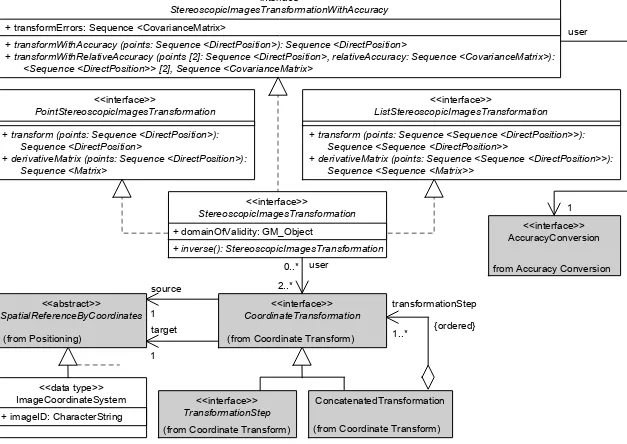
4.1.6. Object Model
StereoscopicImagesTransformationWithAccuracy
+ transformErrors: Sequence <CovarianceMatrix>
+ transformWithAccuracy (points: Sequence <DirectPosition>): Sequence <DirectPosition>
+ transformWithRelativeAccuracy (points [2]: Sequence <DirectPosition>, relativeAccuracy: Sequence <CovarianceMatrix>): <Sequence <DirectPosition>> [2], Sequence <CovarianceMatrix>
+ transform (points: Sequence <DirectPosition>): Sequence <DirectPosition>
+ derivativeMatrix (points: Sequence <DirectPosition>): Sequence <Matrix>
<<interface>>
ListStereoscopicImagesTransformation
+ transform (points: Sequence <Sequence <DirectPosition>>): Sequence <Sequence <DirectPosition>>
+ derivativeMatrix (points: Sequence <Sequence <DirectPosition>>): Sequence <Sequence <Matrix>>
TransformationStep
<<interface>>
ImageCoordinateTransformation
<<interface>>
ImageGeometryTransformation
<<interface>>
CoordinateConversion
<<interface>>
PolynomialImageTransformation
<<interface>>
ImageRectification
(from Coordinate Conversion)
<<interface>>
GroundShape
<<interface>>
ShapeModel
+ intersection (ray: Sequence <CoordinatePoint>): CoordinatePoint
+ absoluteAccuracy (point: CoordinatePoint): CovarianceMatrix
0..* user (from Coordinate Transform)
<<interface>>
ElevationModel
<<interface>>
ElevationSurface
<<interface>>
DatumTransformation
(from Datum Transformation)
This class diagram is based on the diagram for the Coordinate Transform package, developed by the Coordinate Transformation Working Group (CT WG). That class diagram has been augmented to show how the Image Coordinate Transformation Services should be combined with the Ground Coordinate Transformation Services. The key additions included in this diagram are the:
1. Stereoscopic Images Transformation class, whose objects each use two or more objects of the Coordinate Transformation class. This class provides capabilities for using two or more stereoscopic images together, to derive 3-D ground position coordinates without using ground elevation or shape data.
2. Point Stereoscopic Images Transformation, List Stereoscopic Images Transformation, and Stereoscopic Images Transformation With Accuracy classes. These classes define interfaces for different purposes, that are realized by the Stereoscopic Images Transformation class. 3. Image Coordinate System subclass of the Spatial Reference By Coordinates class, that defines
the coordinate reference system for a Coordinate Transformation object which transforms coordinates to or from image coordinates. This Image Coordinate System class also defines the source and target coordinate reference systems for a Coordinate Transformation object that transforms between two different image coordinate systems.
4. Image Geometry Transformation subclass of the Transformation Step class, that provides transformations between image and ground coordinates.
5. Image Coordinate Transformation subclass of the Transformation Step class, that provides transformations between different image coordinates for the same original image. 6. Polynomial Transformation and Image Rectification subclasses of the Image Coordinate
Transformation class.
7. Ground Shape class, that defines the shape and position of the ground surface for monoscopic image to ground transformation operations of the Image Geometry Transformation class. 8. Elevation Surface, Elevation Model, and Shape Model subclasses of the Ground Shape class,
that use different forms of shape data.
Author’s Note: The six shaded classes shown in Figure 2 are intended to be the same as the classes with the same names in the Transformation package of the CT abstract model, see Abstract Specification Topic 2. These classes include CoordinateTransformation,
ConcatenatedTransformation, TransformationStep (shown twice), and
SpatialReferenceByCoordinates. The IES SIG and CT WG plan to work together to modify this diagram and the Transformation package to make the shared classes essentially identical. To keep this diagram simple and easier to understand, Figure 2 omits certain parts of the Transformation package diagram. The Transformation diagram elements omitted in this diagram include:
1. The MathTransform and Parameter classes, and their association with the TransformationStep class (that implement TransformationStep objects)
2. The association of the Parameter class to the CovarianceElement class (that holds absolute and relative accuracy data for the Parameters)
3. Two notes
Some of the classes shown in Figure 2 may have additional attributes and operations, not shown here. For example, all subclasses inherit all the abstract operations included in their ancestor classes, but those operations are not repeated in this diagram. Also, several classes are expected to have subclasses that are not specifically identified and not shown in this overview diagram. The classes expected to have (additional) subclasses include:
1. Stereoscopic Images Transformation, for different numbers of images and for different methods of computing absolute and relative accuracies
7. Shape Model, using different forms of additional shape data
The following sections provide more information about each image transformations package class shown in Figure 4-1 and Figure 4-2.
4.1.7. Class Name: StereoscopicImagesTransformation
Package Class Belongs to: Image TransformationsDocumentation:
This service class determines the 3-D ground position corresponding to the specified positions in two or more stereoscopic images, by using the corresponding image geometry models. This class alternately determines the positions in two or more stereoscopic images corresponding to the specified 3-D ground position. This class provides a set of operations similar to the Coordinate Transformation class, and the three interface classes realized by that class, adapted to using two or more stereoscopic images. This class uses an object of the Coordinate Transformation class for each image, to transform between the corresponding image and ground positions.
Subclasses:
Subclasses are expected to be defined using different methods of computing absolute and relative accuracies. Subclasses could also be defined using different ray intersection algorithms and/or different numbers of stereoscopic images, such as only two images. The subclasses support identical interfaces except for any parameters needed by different methods of computing absolute and relative accuracies.
Superclass: none
Realizes Interfaces:
PointStereoscopicImagesTransformation ListStereoscopicImagesTransformation
StereoscopicImagesTransformationWithAccuracy
Note: The use of realization is similar to but not equal to inheritance. An Interface does not constitute a complete class definition, but defines some basic class-like behavior, such as a set of attribute, association, and/or operation signatures that form a logically consistent group. In this model, realization is used to logically group signatures into three functionally related groups:
• transformations that transform one point at a time • transformations that transform a list of points at a time
• transformations that determine the accuracy of transformed points In any implementation of this model, these 3 groups shall be handled as units, either implementing all of the operations in a group or none of them.
Stereotype: interface
Associations: user (of 2..*) CoordinateTransformation Attributes:
domainOfValidity: GM_Object
The domainOfValidity attribute is a geometry that defines the geographical region where this Stereoscopic Images Transformation object is appropriate to use. The coordinate reference system of this geometry may be a source, target, or any standard coordinate reference system. This OGC geometry object supports the GM_Object interface. The GM_Object interface, as described in Topic 1: Feature Geometry, includes operations that will check whether or not a specified point or geometry is spatially within the domain of this GM_Object.
inverse(): StereoscopicImagesTransformation
This operation returns another Stereoscopic Images Transformation object that reverses the actions of this Stereoscopic Images Transformation object. The target of the inverse
transformation is the source of the original, and the source of the inverse transformation is the target of the original. Using the original transform followed by the inverse transform will result in an identity map on the source coordinate space, when allowances for error are made.
4.1.8. Class Name: PointStereoscopicImagesTransformation
Package Class Belongs to: Image Transformations Documentation:
This class defines a coordinate transformation operation that determines one 3-D ground position corresponding to the specified positions in two or more stereoscopic images. This class alternately defines an operation that transforms the coordinates of one ground point position into the corresponding image coordinates in two or more images.
Note that the input and output positions are of type DirectPosition, in order to include the association to the proper SpatialReferenceByCoordinates (which is needed with some input and output positions). However, each DirectPosition includes position accuracy data, which is not needed with the input and output positions.
Superclass: none
Stereotype: interface
Associations: none
Attributes: none Operations:
transform (points: Sequence <DirectPosition>): Sequence <DirectPosition>
This operation performs one of two similar functions, depending on whether the source SpatialReferenceByCoordinates is a ground or image coordinate system.
When the source is a ground coordinate system, this operation transforms the specified position of one point given in the source ground coordinate system to the corresponding positions of the point in two or more images.
When the source is an image coordinate system, this operation computes the one position in the (source) ground coordinate system that best fits the specified positions of this point in each of two or more images.
derivativeMatrix (points: Sequence <DirectPosition>): Sequence<Matrix>
This operation performs one of two similar functions, depending on whether the source SpatialReferenceByCoordinates is a ground or image coordinate system.
When the source is a ground coordinate system, this operation returns a list of matrices of the partial derivatives of the image coordinates with respect to the source ground coordinates. These partial derivatives are determined at the one specified position in the source ground coordinate reference system. The returned list of partial derivative matrices includes a matrix for each image used by this object.
When the source is an image coordinate system, this operation returns a list of matrices of the partial derivatives of the ground coordinates with respect to the image coordinates in two or more images. These partial derivatives are determined at the specified positions in these images, which are normally the positions of the same ground point in the different images.
4.1.9. Class Name: ListStereoscopicImagesTransformation
Package Class Belongs to: Image Transformations Documentation:
This class defines a coordinate transformation operation that determines a list of one or more 3-D ground positions, each corresponding to the specified positions in two or more