A STEP TOWARDS DYNAMIC SCENE ANALYSIS WITH ACTIVE MULTI-VIEW RANGE
IMAGING SYSTEMS
Martin Weinmann and Boris Jutzi
Institute of Photogrammetry and Remote Sensing, Karlsruhe Institute of Technology (KIT) Kaiserstr. 12, 76128 Karlsruhe, Germany
{martin.weinmann, boris.jutzi}@kit.edu
Commission III, WG III/5
KEY WORDS:LIDAR, Multisensor, Point Cloud, Imagery, Automation, Close Range, Dynamic
ABSTRACT:
Obtaining an appropriate 3D description of the local environment remains a challenging task in photogrammetric research. As terrestrial laser scanners (TLSs) perform a highly accurate, but time-dependent spatial scanning of the local environment, they are only suited for capturing static scenes. In contrast, new types of active sensors provide the possibility of simultaneously capturing range and intensity information by images with a single measurement, and the high frame rate also allows for capturing dynamic scenes. However, due to the limited field of view, one observation is not sufficient to obtain a full scene coverage and therefore, typically, multiple observations are collected from different locations. This can be achieved by either placing several fixed sensors at different known locations or by using a moving sensor. In the latter case, the relation between different observations has to be estimated by using information extracted from the captured data and then, a limited field of view may lead to problems if there are too many moving objects within it. Hence, a moving sensor platform with multiple and coupled sensor devices offers the advantages of an extended field of view which results in a stabilized pose estimation, an improved registration of the recorded point clouds and an improved reconstruction of the scene. In this paper, a new experimental setup for investigating the potentials of such multi-view range imaging systems is presented which consists of a moving cable car equipped with two synchronized range imaging devices. The presented setup allows for monitoring in low altitudes and it is suitable for getting dynamic observations which might arise from moving cars or from moving pedestrians. Relying on both 3D geometry and 2D imagery, a reliable and fully automatic approach for co-registration of captured point cloud data is presented which is essential for a high quality of all subsequent tasks. The approach involves using sparse point clouds as well as a new measure derived from the respective point quality. Additionally, an extension of this approach is presented for detecting special objects and, finally, decoupling sensor and object motion in order to improve the registration process. The results indicate that the proposed setup offers new possibilities for applications such as surveillance, scene reconstruction or scene interpretation.
1 INTRODUCTION
An appropriate 3D description of the local environment is repre-sented in the form of point clouds consisting of a large number of measured 3D points and, optionally, different attributes for each point. Such point clouds can directly be acquired with different scanning devices such as terrestrial laser scanners (TLSs), time-of-flight (ToF) cameras or devices based on the use of structured light. However, a single scan often is not sufficient and hence, multiple scans have to be acquired from different locations in or-der to get a full scene coverage. As each captured point cloud represents 3D information about the local area only with respect to a local coordinate frame, a basic task for many applications consists of a point cloud registration. This process serves for es-timating the transformation parameters between different point clouds and transforming all point clouds into a common coordi-nate frame. Existing techniques for point cloud registration rely on
• 3D geometry,
• 3D geometry and the respective 2D representation as range image and
• 3D geometry and the corresponding 2D representation of intensity values.
Standard approaches involving only the spatial 3D information for calculating the transformation parameters between two par-tially overlapping point clouds are based on the Iterative Closest Point (ICP) algorithm (Besl and McKay, 1992) and its variants
(Rusinkiewicz and Levoy, 2001). Iteratively minimizing the dif-ference between two point clouds however shows a high compu-tational effort for large numbers of points. Hence, other regis-tration approaches are based on information extracted from the point clouds. This information may for instance be derived from the distribution of the points within each point cloud by using the normal distributions transform (NDT) either on 2D scan slices (Brenner et al., 2008) or in 3D (Magnusson et al., 2007). If the presence of regular surfaces can be assumed in the local environ-ment, various types of geometric features are likely to occur, e.g. planes, spheres and cylinders. These features can directly be ex-tracted from the point clouds and strongly support the registration process (Brenner et al., 2008; Pathak et al., 2010; Rabbani et al., 2007). In cluttered scenes, descriptors representing local surface patches are more appropriate. Such descriptors may be derived from geometric curvature or normal vectors of the local surface (Bae and Lichti, 2008).
As the scans are acquired on a regular grid resulting from a cylin-drical or spherical projection, the spatial 3D information can also be represented as range image. This range image provides addi-tional features such as distinctive feature points which strongly support the registration process (Barnea and Filin, 2008; Steder et al., 2010).
typ-ically is represented as intensity image. This intensity image might provide a higher level of distinctiveness than shape fea-tures (Seo et al., 2005) and thus information about the local en-vironment which is not represented in the range measurements. Hence, the registration process can efficiently be supported by using reliable feature correspondences between the respective in-tensity images. Although different kinds of features can be used for this purpose, most of the current approaches are based on the use of feature points or keypoints as these tend to yield the most robust results for registration without assuming the presence of regular surfaces in the scene. Distinctive feature points simplify the detection of point correspondences and for this reason, SIFT features are commonly used. These features are extracted from the co-registered camera images (Al-Manasir and Fraser, 2006; Barnea and Filin, 2007) or from the reflectance images (Wang and Brenner, 2008; Kang et al., 2009). For all point correspondences, the respective 2D feature points are projected into 3D space us-ing the spatial information. This yields a much smaller set of 3D points for the registration process and thus a much faster estima-tion of the transformaestima-tion parameters between two point clouds. Furthermore, additional constraints considering the reliability of the point correspondences (Weinmann et al., 2011; Weinmann and Jutzi, 2011) allow for increasing the accuracy of the registra-tion results.
Once 2D/2D correspondences are detected between images of different scans, the respective 3D/3D correspondences can be de-rived. Thus knowledge about the closest neighbor is available and the computationally expensive ICP algorithm can be replaced by a least squares adjustment. Least squares methods involv-ing all points of a scan have been used for 3D surface matchinvolv-ing (Gruen and Akca, 2005), but since a large overlap between the point clouds is required which can not always be assumed, typi-cally sparse 3D point clouds consisting of a very small subset of points are derived from the original 3D point clouds (Al-Manasir and Fraser, 2006; Kang et al., 2009). To further exclude unre-liable 3D/3D correspondences, filtering schemes based on the RANSAC algorithm (Fischler and Bolles, 1981) have been pro-posed in order to estimate the rigid transformation aligning two point clouds (Seo et al., 2005; B¨ohm and Becker, 2007; Barnea and Filin, 2007).
For dynamic environments, terrestrial laser scanners which per-form a time-dependent spatial scanning of the scene are not suited. Furthermore, due to the background illumination, monitoring out-door environments remains challenging with devices based on structured light such as the Microsoft Kinect device which uses random dot patterns of projected infrared points for getting re-liable and dense close-range measurements in real-time. Hence, this paper is focused on airborne scene monitoring with range imaging devices mounted on a sensor platform. Although the captured point clouds are corrupted with noise and the field of view is very limited, a fast, but still reliable approach for point cloud registration is presented. The approach involves an ini-tial camera calibration for increased accuracy of the respective 3D point clouds and the extraction of distinctive 2D features. The detection of 2D/2D correspondences between two succes-sive frames and the subsequent projection of the respective 2D points into 3D space yields 3D/3D correspondences. Using such sparse point clouds significantly increases the performance of the registration process, but the influence of outliers has to be con-sidered. Hence, a new weighting scheme derived from the re-spective point quality is introduced for adapting the influence of each 3D/3D correspondence on a weighted rigid transformation. Additionally, an extension of this approach is presented which is based on the already detected features and focuses on a decou-pling of sensor and object motion.
The remainder of this paper is organized as follows. In Section 2, the proposed methodology for successive pairwise registration in dynamic environments is described as well as a simple extension for decoupling sensor and object motion. The configuration of the sensor platform is outlined in Section 3. Subsequently, the performance of the presented approach is tested in Section 4. The derived results are discussed in Section 5. Finally, in Section 6, the content of the entire paper is concluded and suggestions for future work are outlined.
2 METHODOLOGY
The proposed methodology provides fast algorithms which are essential for time-critical surveillance applications and should be capable for a real-time implementation on graphic processors. After data acquisition (Section 2.1), a preprocessing has to be carried out in order to get the respective 3D point cloud (Section 2.2). However, the point cloud is corrupted with noise and hence, a quality measure is calculated for each point of the point cloud (Section 2.3). Subsequently extracting distinctive features from 2D images allows for detecting reliable 2D/2D correspondences between different frames (Section 2.4), and projecting the respec-tive 2D points into 3D space yields 3D/3D correspondences of which each 3D point is assigned a value for the respective point quality (Section 2.5). The point cloud registration is then carried out by estimating the rigid transformation between two sparse point clouds where the weights of the 3D/3D correspondences are derived from the point quality of the respective 3D points (Sec-tion 2.6). Finally, a feature-based method for object detec(Sec-tion and segmentation is introduced (Section 2.7) which can be applied for decoupling sensor and object motion.
2.1 Data Acquisition
In contrast to the classical stereo observation techniques with pas-sive sensors, where data from at least two different viewpoints has to be captured, the monostatic sensor configuration of the PMD[vision] CamCube 2.0 preserves information without the need of a co-registration of the captured data. A PMD[vision] CamCube 2.0 simultaneously captures various types of data, i.e. geometric and radiometric information, by images with a single shot. The images have a size of204×204pixels which corre-sponds to a field of view of40◦
×40◦
. Thus, the device provides measurements with an angular resolution of approximately0.2◦
. For each pixel, three features are measured, namely the respec-tive rangeR, the active intensityIaand the passive intensityIp. The active intensity depends on the illumination emitted by the sensor, whereas the passive intensity depends on the background illumination arising from the sun or other external light sources. As a single frame consisting of a range imageIR, an active
in-tensity imageIaand a passive intensity imageIpcan be updated
with high frame rates of more than25releases per second, this device is well-suited for capturing dynamic scenes.
2.2 Preprocessing
In a first step, the intensity information of each frame, i.e.Iaand Ip, has to be adapted. This is achieved by applying a histogram
normalization of the form
In=
I−Imin
Imax−Imin
·255 (1)
For all subsequent tasks, it is essential to get the 3D informa-tion as accurate as possible. Due to radial lens distorinforma-tion and decentring distortion, however, the image coordinates have to be adapted in order to be able to appropriately capture a scene. Hence, a camera calibration is carried out for the used devices. This yields a corrected grid of image coordinates with the prin-cipal point as origin of the new 2D coordinate frame. For each pointx = (x, y)on the new grid, the respective 3D informa-tion in the local coordinate frame can then be derived from the measured range valueRwith
R=pX2+Y2+Z2 (2)
and a substitution ofXandY with
X= x
fx
·Z and Y = y
fy
·Z (3)
wherefxandfyare the focal lengths inx- andy-direction. Solv-ing for the depthZalong the optical axis yields
Z =r R
x fx
2 +y
fy
2 + 1
(4)
and thus, the 3D pointX= (X, Y, Z)corresponding to the 2D pointx= (x, y)has been calculated. Consequently, the
undis-tortion of the 2D grid and the projection of all points onto the new grid lead to the respective point cloud data.
Figure 1: Image representation of normalized active intensity, normalized passive intensity and range data.
2.3 Point Quality Assessment
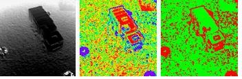
For further calculations, it is feasible to derive a measure which describes the quality of each 3D point. Those points which arise from objects in the scene will probably provide a smooth surface, whereas points corresponding to the sky or points along edges of the objects might be very noisy. Hence, for each point on the reg-ular 2D grid, the standard deviationσof all range values within a 3×3neighborhood is calculated and used as a measure describ-ing the reliability of the range information of the center point. This yields a 2D confidence map according to which the influ-ence of a special point on subsequent tasks can be weighted. For the example depicted in Figure 1, the corresponding confidence map is shown in Figure 2.
Figure 2: Range image, confidence map (pseudo-color represen-tation where reliable points are marked in red and unreliable ones in blue) and thresholded confidence map (green:σ≤0.05m).
2.4 2D Feature Extraction
As each frame consists of range and image data acquired on a reg-ular grid, the alignment of two point clouds is based on using both
kinds of information. However, instead of using the whole 3D in-formation available which results in a high computational effort, the intensity information is used to derive a much smaller set of 3D points. Hence, distinctive 2D features are extracted from the intensity information which later have to be projected into 3D space. For this purpose, the Scale Invariant Feature Transform (SIFT) (Lowe, 2004) is carried out on the normalized active in-tensity image as well as on the normalized passive inin-tensity im-age. This yields distinctive keypoints and the respective local descriptors which are invariant to image scaling and image rota-tion, and robust with respect to image noise, changes in illumina-tion and small changes in viewpoint. The vector representaillumina-tion of these descriptors allows for deriving correspondences between different images by considering the ratio
r=d(N1)
d(N2) (5)
whered(Ni)withi = 1,2denotes the Euclidean distance of a descriptor belonging to a keypoint in one image to thei-th near-est neighbor in the other image. This ratior ∈ [0,1]describes the distinctiveness of a keypoint. Distinctive keypoints arise from low values and hence, the ratiorhas to be below a certain thresh-oldtdes. Typical values for this threshold are between0.6and 0.8. This procedure yieldsnacorrespondences between the nor-malized active intensity images of the two frames andnp corre-spondences between the normalized passive intensity images. For the registration process, it is not necessary to distinguish between the two types of correspondences as only the spatial relations are of interest. Hence, a total number ofn =na+np correspon-dences is utilized for subsequent tasks.
2.5 Point Projection
In contrast to the measured range and intensity data which are only available on a regular grid, the location of SIFT features is determined with subpixel accuracy. Hence, an interpolation has to be carried out in order to obtain the respective 3D information as well as the respective range reliability. For this purpose, a bi-linear interpolation is used. Assuming a total number ofmSIFT features extracted from an image, this yields a set of samplessi withi= 1, . . . , mwhich are described by a 2D locationxi, a 3D
locationXiand a quality measureσi. Compared to the original
point cloud, the derived 3D pointsXirepresent a much smaller
point cloud where each point is assigned a quality measureσi.
Extending this on two frames withm1 and m2 SIFT features, between whichn ≤min{m1, m2}correspondences have been detected, yields additional constraints. From the set of alln cor-respondences, it is now possible to derive subsets of
• 2D/2D correspondencesxi ↔ x′
i which can be used for image-based techniques, e.g. using the fundamental matrix (Hartley and Zisserman, 2008),
• 3D/3D correspondencesXi ↔ X′
iwhich can be used for techniques based on the 3D geometry such as the ICP algo-rithm (Besl and McKay, 1992) and approaches estimating a rigid or non-rigid transformation, or
• 3D/2D correspondencesXi ↔ x′
i which can be used for hybrid techniques such as the methods presented in (Wein-mann et al., 2011) and (Wein(Wein-mann and Jutzi, 2011) which involve the EPnP algorithm (Moreno-Noguer et al., 2007).
2.6 Point Cloud Registration
The spatial relation between two point clouds withn3D/3D cor-respondences Xi ↔ X′
resents a translation vector. A fully automatic estimation of the transformation parameters can be derived from minimizing the error between the point clouds. Including a weightingwi∈Rfor each 3D/3D correspondenceXi↔X′
iyields an energy function
Ewith
for the registration process. For minimizing this energy function
E, the registration is carried out by estimating the rigid trans-formation from all 3D/3D correspondences and the weigths are derived from a histogram-based approach. This approach is ini-tialized by dividing the interval[0m,1m]intonb= 100bins of equal size. For all detected correspondences, the calculated qual-ity measuresσiandσ
′
iassigned to the 3D pointsXiandX ′ iare mapped to the respective binsbj andb
′
j. Points with standard deviations greater than1m are mapped to the last bin. The oc-currence of mappings to the different bins is stored in histograms
h= [hj]
are derived. The entries of the cumulative histograms reach from 0to the numbernof detected correspondences. As points with a low standard deviation are more reliable, they should be as-signed a higher weight. For this reason, the inverse cumulative histograms
are calculated. Finally, the weightwiof a 3D/3D correspondence
Xi↔X′
i are considered as quality measures for the re-spective 3D pointsXi and X′
i. Estimating the transformation parameters can thus be carried out for both range imaging de-vices separately. However, as the relative orientation between the devices is already known from a priori measurements and both devices are running synchronized, the rigid transformation can be estimated from the respective correspondences detected by both devices between successive frames. Combining information from both devices corresponds to extending the field of view and this yields more reliable results for the registration process. The ex-tension can be expressed by transforming the projected 3D points
Xiwhich are related to the respective camera coordinate frame
(superscriptc) into the body frame (superscriptb) of the sensor platform according to
whereRbcdescribes the rotation and tbcdenotes the translation
between the respective coordinate frames. For this, it is assumed that the origin of the body frame is in the center between both range imaging devices.
2.7 Object Detection and Segmentation
As 2D SIFT features have already been calculated for the reg-istration process, they can also be utilized for detecting special objects in the scene. This allows for calculating the coarse area of an object and for automatically selecting features which should not be included in the registration process as they arise from ob-jects which are likely to be dynamic. These features have to be treated in a different way as the static background being relevant for registration. For this purpose, image representations of sev-eral objects have to be stored in a database before starting the surveillance application. One of these images contains a tem-plate for the object present in the scene, but from a different measurement campaign at a different place and at a different sea-son. Due to a similar altitude, the active intensity images show a very similar appearance. Comparing the detected SIFT features of the normalized active intensity image to the object templates in the database during the flight yields a maximum similarity to the correct template. Defining a spatial transformation based on the SIFT locations as control points, the template is transformed. The respective area of the transformed template is then assumed to cover the detected object. This procedure allows for detecting both static and moving objects in the scene as well as for decou-pling sensor and object motion. Hence, the presented approach for registration also remains reliable in case of dynamic environ-ments if representative objects are already known.
3 ACTIVE MULTI-VIEW RANGE IMAGING SYSTEMS
The proposed concept focuses on airborne scene monitoring with range imaging devices. For simulating a future operational sys-tem involving such range imaging devices fairly realistically, a scaled test scenario has been set up. However, due to the large payload of several kilograms for the whole system, mounting the required components for data acquisition and data storage on an unmanned aerial vehicle (UAV) still is impracticable. Hence, in order to investigate the potentials of active multi-view range imaging systems, a cable car moving along a rope is used as sensor platform which is shown in Figure 3. The components mounted on this platform consist of
• two range imaging devices (PMD[vision] CamCube 2.0) for recording the data,
• a notebook with a solid state hard disk for efficiently storing the recorded data and
• a12V battery with6.5Ah for independent power supply.
As the relative orientation of the two range imaging devices can easily be changed, the system allows for variable multi-view op-tions with respect to parallel, convergent or divergent data acqui-sition geometries.
However, due to the relatively large influence of noise effects aris-ing from the large amount of ambient radiation in comparison to the emitted radiation as well as from multipath scattering, the uti-lized devices only have a limited absolute range accuracy of a few centimeters and noisy point clouds can be expected. Furthermore, due to the measurement principle of such time-of-flight cameras, the non-ambiguous rangeRnwith
Figure 3: PMD[vision] CamCube 2.0 and model of a cable car equipped with two range imaging devices.
depends on the modulation frequencyfm, wherec0denotes the speed of light. A modulation frequency of20MHz thus corre-sponds to a non-ambiguous range of7.5m. In order to overcome this range measurement restriction, image- or hardware-based un-wrapping procedures have been introduced (Jutzi, 2009; Jutzi, 2012). When dealing with multiple range imaging devices, it also has to be taken into account that these may influence each other and that interferences are likely to occur. This can be overcome by choosing different modulation frequencies.
4 EXPERIMENTAL RESULTS
The estimation of the flight trajectory of a sensor platform re-quires the definition of a global world coordinate frame. This world coordinate frame is assumed to equal the local coordinate frame of the sensor platform at the beginning. The local coor-dinate frame has a fixed orientation with respect to the sensor platform. It is oriented with theX-direction in forward direction tangential to the rope, theY-direction to the right and the Z -direction downwards. For evaluating the proposed methodology, a successive pairwise registration is performed. The threshold for the matching of 2D features is selected astdes= 0.7. The result-ing 2D/2D correspondences are projected into 3D space which yields 3D/3D correspondences. Including the weights in the esti-mation of the rigid transforesti-mation yields position estimates and, finally, an estimated trajectory which is shown in Figure 4 in nadir view and in Figure 5 from the side. The green and blue points describe thinned point clouds captured with both range imaging devices and transformed to the global world coordinate frame.
Figure 4: Projection of the estimated trajectory and thinned point cloud data onto theXY-plane.
A limitation of the experimental setup seems to be the fact that no reference values are available for checking the deviation of the position estimates from the real positions. However, due to the relative orientation of the sensor platform to the rope, the projection of the real trajectory onto theXY-plane should ap-proximately be a straight line. Additionally, the length of the real trajectory projected onto the ground plane can be estimated from aerial images or simply be measured. Here, the distance∆ground between the projections of the end points onto the ground plane has been measured as well as the difference∆altitude between maximum and minimum altitude. From the measured values of ∆ground = 7m and∆altitude = 1.25m, a total distance of
Figure 5: Projection of the estimated trajectory and thinned point cloud data onto theXZ-plane.
approximately7.11m can be assumed. A comparison between the start position and the point with the maximum distance on the estimated trajectory results in a distance of6.90m. As a con-sequence, the estimated trajectory can be assumed to be of rela-tively high quality. The results for a subsequent object detection and segmentation is illustrated for an example frame in Figure 6.
Figure 6: SIFT-based object detection and segmentation: normal-ized active intensity image, template and transformed template (upper row, from left to right). The corresponding point cloud for the area of the transformed template and the sensor position (red dot) are shown below.
5 DISCUSSION
The presented methodology is well-suited for dynamic environ-ments. Instead of considering the whole point clouds, the prob-lem of registration is reduced on sparse point clouds of physically almost identical 3D points. Due to this fact and the non-iterative processing scheme, the proposed algorithm for point cloud reg-istration is very fast which is required for monitoring in such demanding environments. Although the current Matlab imple-mentation is not fully optimized with respect to parallelization of tasks, a total time of approximately1.63s is required for pre-processing, point quality assessment, feature extraction and point projection. Further0.46s are required for feature matching, cal-culation of weights and point cloud registration. This can signif-icantly be reduced with a GPU-implementation of SIFT, as the calculation of SIFT features already takes approximately1.54s.
weighting the influence of each 3D/3D correspondence on the es-timation of the rigid transformation. As most of the 3D points of a frame are assigned a higher quality, the introduced weights of 3D/3D correspondences with low quality are approximately0. Consequently, the presented approach shows similar characteris-tics as a RANSAC-based approach, but it is faster and a deter-ministic solution for the transformation parameters is calculated.
6 CONCLUSIONS AND FUTURE WORK
In this paper, an experimental setup involving a moving sensor platform with multiple and coupled sensor devices for monitor-ing in low altitudes has been presented. For successive pair-wise registration of the measured point clouds, a fast and reliable image-based approach has been presented which can also cope with dynamic environments. The concept is based on the extrac-tion of distinctive 2D features from the image representaextrac-tion of measured intensity information and the projection into 3D space with respect to the measured range information. Detected 2D/2D correspondences between two frames, which have a high reliabil-ity, thus yield sparse 3D point clouds of 3D/3D correspondences. For increased robustness, the influence of each 3D/3D correspon-dence is weighted with a new measure derived from the quality of the respective 3D points. Finally, the point cloud registration is carried out by estimating the rigid transformation between two sparse point clouds which involves the calculated weights. As demonstrated, this approach can easily be extended towards us-ing the already detected features for object detection and, even further, decoupling sensor and object motion which significantly improves the registration process in dynamic environments. The results indicate that the presented concept of active multi-view range imaging strongly supports navigation, point cloud registra-tion and scene analysis.
The presented methodology can further be extended towards the detection, the segmentation and the recognition of multiple static or moving objects. Furthermore, a tracking method for estimating the trajectory of a moving object could be introduced as well as a model for further stabilizing the estimated trajectory of the sensor platform. Hence, active multi-view range imaging systems have a high potential for future research on dynamic scene analysis.
ACKNOWLEDGEMENTS
The authors would like to thank Michael Weinmann (Institute of Computer Science II, University of Bonn) for helpful discussions and Peter Runge (Geodetic Institute, Karlsruhe Institute of Tech-nology) for constructing the sensor platform. Further thanks go to Andr´e Dittrich and Annette Schmitt for assistance during the measurement campaign.
REFERENCES
Al-Manasir, K. and Fraser, C. S., 2006. Registration of terrestrial laser scanner data using imagery. The Photogrammetric Record
21(115), pp. 255–268.
Bae, K.-H. and Lichti, D. D., 2008. A method for automated registration of unorganised point clouds. ISPRS Journal of Pho-togrammetry and Remote Sensing63(1), pp. 36–54.
Barnea, S. and Filin, S., 2007. Registration of terrestrial laser scans via image based features.The International Archives of the Photogrammetry, Remote Sensing and Spatial Information Sci-ences36 (Part 3), pp. 32–37.
Barnea, S. and Filin, S., 2008. Keypoint based autonomous reg-istration of terrestrial laser point-clouds. ISPRS Journal of Pho-togrammetry and Remote Sensing63(1), pp. 19–35.
Besl, P. J. and McKay, N. D., 1992. A method for registration of 3-D shapes.IEEE Transactions on Pattern Analysis and Machine Intelligence14(2), pp. 239–256.
B¨ohm, J. and Becker, S., 2007. Automatic marker-free registra-tion of terrestrial laser scans using reflectance features. Optical 3-D Measurement TechniquesVIII, pp. 338–344.
Brenner, C., Dold, C. and Ripperda, N., 2008. Coarse orientation of terrestrial laser scans in urban environments.ISPRS Journal of Photogrammetry and Remote Sensing63(1), pp. 4–18.
Fischler, M. A. and Bolles, R. C., 1981. Random sample con-sensus: A paradigm for model fitting with applications to im-age analysis and automated cartography.Communications of the ACM24(6), pp. 381–395.
Gruen, A. and Akca, D., 2005. Least squares 3D surface and curve matching. ISPRS Journal of Photogrammetry and Remote Sensing59(3), pp. 151–174.
Hartley, R. I. and Zisserman, A., 2008. Multiple view geometry in computer vision. University Press, Cambridge.
Jutzi, B., 2009. Investigations on ambiguity unwrapping of range images. The International Archives of the Photogrammetry, Re-mote Sensing and Spatial Information Sciences38 (Part 3 / W8), pp. 265–270.
Jutzi, B., 2012. Extending the range measurement capabilities of modulated range imaging devices by time-frequency multiplex-ing.AVN - Allgemeine Vermessungs-Nachrichten2 / 2012.
Kang, Z., Li, J., Zhang, L., Zhao, Q. and Zlatanova, S., 2009. Au-tomatic registration of terrestrial laser scanning point clouds us-ing panoramic reflectance images.Sensors9(4), pp. 2621–2646.
Lowe, D. G., 2004. Distinctive image features from scale-invariant keypoints. International Journal of Computer Vision
60(2), pp. 91–110.
Magnusson, M., Lilienthal, A. and Duckett, T., 2007. Scan regis-tration for autonomous mining vehicles using 3D-NDT. Journal of Field Robotics24(10), pp. 803–827.
Moreno-Noguer, F., Lepetit, V. and Fua, P., 2007. Accurate non-iterative O(n) solution to the PnP problem. IEEE 11th Interna-tional Conference on Computer Vision, pp. 1–8.
Pathak, K., Birk, A., Vaskevicius, N. and Poppinga, J., 2010. Fast registration based on noisy planes with unknown correspon-dences for 3-D mapping. IEEE Transactions on Robotics26(3), pp. 424–441.
Rabbani, T., Dijkman, S., van den Heuvel, F. and Vosselman, G., 2007. An integrated approach for modelling and global regis-tration of point clouds. ISPRS Journal of Photogrammetry and Remote Sensing61(6), pp. 355–370.
Rusinkiewicz, S. and Levoy, M., 2001. Efficient variants of the ICP algorithm. Proceedings of the Third International Confer-ence on 3D Digital Imaging and Modeling, pp. 145–152.
Seo, J. K., Sharp, G. C. and Lee, S. W., 2005. Range data reg-istration using photometric features. Proceedings of the IEEE Computer Society Conference on Computer Vision and Pattern Recognition2, pp. 1140–1145.
Steder, B., Grisetti, G. and Burgard, W., 2010. Robust place recognition for 3D range data based on point features. IEEE In-ternational Conference on Robotics and Automation, pp. 1400– 1405.
Wang, Z. and Brenner, C., 2008. Point based registration of ter-restrial laser data using intensity and geometry features. The In-ternational Archives of the Photogrammetry, Remote Sensing and Spatial Information Sciences37 (Part B5), pp. 583–589.
Weinmann, Ma. and Jutzi, B., 2011. Fully automatic image-based registration of unorganized TLS data.The International Archives of the Photogrammetry, Remote Sensing and Spatial Information Sciences38 (Part 5 / W12).
![Figure 3: PMD[vision] CamCube 2.0 and model of a cable carequipped with two range imaging devices.](https://thumb-ap.123doks.com/thumbv2/123dok/3239443.1397179/5.595.76.271.519.610/figure-vision-camcube-model-cable-carequipped-imaging-devices.webp)
