Reducing of Energy Process on Refinery Wastewater
Treatment using Membrane Ultrafiltration
Erna Yuliwati
a,b,*, Amrifan Saladin Mohruni
c, Ahmad Fauzi Ismail
a,da
Advanced Membrane Technology Research Centre (AMTEC), b Department of Industrial Engineering, Faculty of Engineering,
Universitas Bina Darma, 30251 Palembang, Indonesia, Tel. +62 (711) 515-679; Fax: +62 (711) 518-000
cDepartment of Mechanical Engineering,Faculty of Engineering, Sriwijaya University, Indralaya 30662, Indonesia
Tel. +62 (711)580-062; Fax: +62 (711) 580-741
dFaculty of Petroleum and Renewable Energy Engineering,
Universiti Teknologi Malaysia, 81310 UTM, Skudai Johor, Malaysia Tel. +60 (7) 553-5592; Fax: +60 (7) 558-1463
*Corresponding author: [email protected]
ABSTRACT
Application of membrane ultrafiltration (UF) for industrial wastewater treatment is still in its infancy due to the significant variety in wastewater composition and high operational costs. Aim of this study was to investigate UF membrane morphology and performance for refinery produced wastewater treatment. Submerged UF bundle was equipped using PVDF hollow fibers, which were prepared via the phase inversion method by dispersing LiCl.H2O and TiO2 in the dope. Comparison of
morphological and performance tests was conducted on prepared membranes in term of membrane wettability, tensile testing, roughness measurement, mean pore size and surface porosity. An experimental set-up comprised mainly of submerged UF reservoir, circulation pump and aerator were used throughout investigation at vacuum pressure. Fouling characteristics for fibers fouled with suspended solid matter was also investigated. Mixed liquor suspended solid (MLSS) of 3 g/L and 4.5 g/L were assessed by using submerged membrane with varied air bubble flow rates. Results showed effect of air flow rate of 2.4 ml/min increased flux, total suspended solids and sulfide removal of 148.82 L/m2h, 99.82 % and 89.2%, respectively due to increase of turbulence around fibers, which exerts shear stress to minimize particles deposited on membrane surface and available option to reduce energy process.
Keywords: submerged membrane, refinery wastewater, minimizing energy process, ultrafiltration.
1. INTRODUCTION
Low pressure membrane processes such as ultrafiltration (UF) is being increasingly used for wastewater treatment. The properties of feed have also a major impact on membrane fouling. However, fouling, which can affect the permeate quality and operating cost, is a major limitation for their broader implementation. Particulate matter, inorganic and organic materials (e.g. sulfide, phenols) are potential contributors to membrane fouling in refinery wastewater treatment [1]-[3]. A fouling layer, composed of suspended solids, inorganic and organic complexes forms on the membrane surface. The properties of this fouling layer largely control the membrane performance. Preventing or reducing of the formation of this fouling layer by using critical flux concept or making this layer more reversible, could enhance the performance of the membrane processes. The reversibility of fouling layer as well as the critical flux of suspensions appear to be dependent on hydrodynamic conditions and physicochemical properties [4]-[7].
The aim of this study was to investigated the effect of mixed liquor suspended solids concentration and air bubbles flow rate on flux and fouling reversibility. The more understanding of the fouling mechanism and optimized process conditions for refinery wastewater treatment using submerged ultrafiltration was described clearly.
2. EXPERIMENTAL
2.1 Materials
Ultrafiltration membranes have been prepared using Kynar®740 PVDF polymer pellets which were purchased from Arkema Inc., Philadelphia, USA. The solvent N,N-dimethylacetamide (DMAc,Aldrich Chemical) (Synthesis Grade, Merck, 99%) was used as polymer solvent without further purification. Lithium chloride monohydrate (LiCl·H2O) and nanoparticles titanium dioxide (TiO2) were used as inorganic additives. Both chemical additives were purchased from Sigma-Aldrich and used as received. Glycerol was purchased from MERCK (Germany) and used as non-solvent for the post treatment of membrane. In all cases, tap water was used as the external coagulation bath medium in the spinning process.
2.2 Membrane preparation
PVDF hollow fiber UF membranes were spun at room temperature by a dry-jet wet spinning method. The spinning solutions were divided into two batches. Membranes were prepared from 19 wt.% PVDF in DMAc at 10 wt.% TiO2 concentrations and LiCl·H2O was maintained at 5.2 wt.% of the weight of the PVDF, as shown in previous study respectively [12]. The mixture was stirred to ensure thorough wetting of polymer pellets, prior to the addition of appropriate amounts of LiCl·H2O at 50 °C. TiO2 was then added to the polymer dope mixtures which were continuously stirred for 48 h (IKA-20-W) at 500 rpm until a homogenous solution was formed. In general, the polymer solution was pressurized through spinneret with controlled extrusion rate, while the internal coagulant was adjusted at 1.4 mL/min. The hollow fiber that emerged from the tip of the spinneret was guided through the two water baths at a take up velocity of 13.7 cm/s, carefully adjusted to match the free falling velocity before it landed in a final collection bath to complete the solidification process. The spun hollow fibers were immersed in the water bath for a period of 3 days, with daily change of the water, to remove the residual DMAc and the additives. The hollow fibers were then post-treated using 10 wt.% glycerol aqueous solution as a non-solvent exchange for 1 day in order to minimize fiber shrinkage and pore collapse. After the fibers were dried for 3 days, they were ready for making hollow fiber test modules.
2.3 Submerged ultrafiltration process
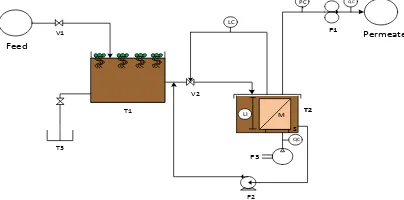
The permeation flux and rejection of PVDF hollow fiber membranes for synthetized refinery wastewater, as listed in Table 1, were measured by submerged ultrafiltration experimental equipment as shown in Figure 1 [13]. An in-house produced U-shape hollow fiber module, with a filtration area of 11.23 dm2, was submerged in prepared suspension in membrane reservoir with volume of 14 L. A cross-flow stream was produced by air bubbling generated by a diffuser situated underneath the submerged membrane module for mechanical cleaning of the membrane module. The air bubbling flow rates per unit projection membrane area was set constantly at 2.4 mL/min in order to maintain proper turbulence. The filtration pressure was supplied by a vacuum pump and controlled by a needle valve. Permeate flow rates were continually recorded using flow meter respectively.
Table 1: Composition of synthetic refinery wastewater with standard deviation (S.D.) and Standard B of national standard for wastewater and water discharged [14].
Constituent, unit Concentration (S.D.) Standard B
pH 6.7 5.5 – 9.0
COD, mg/L 555.0 (0.25) 200
NH3-N, mg/L 29.1 (1.02) 20.0
Suspended Solid, mg/L 213.0 (0.07) 100.0
Source: Parameter Limits of Effluent of Standard B Environmental Quality Regulation 2009.
fibers. In order to enhance membrane hydrophilicity of PVDF membranes, LiCl and TiO2 was added to the spinning dope during membrane preparation process with the effort to improve membrane water productivity. The porous structure and possible hydrophilicity of the TiO2 nanoparticles was directly correlated with porosity and might be responsible for the higher liquid uptake. The details of the membrane fabrication process and its properties determination procedure could be found in previous study [15].
Figure 1: Submerged membrane system for refinery wastewater treatment (V1: wastewater valve, T1: pretreatment tank, V2:feed membrane reservoir valve, S: sparger, M: membrane module, T2: feed reservoir, T3: effluent tank,P1: peristaltic pump, P2: centrifugal pump, P3: air pump, QC: flow control, LC: liquid control, LI: level indicator, PC: pressure control.
The filtration experiments were carried out in vacuum condition created using a peristaltic pump (Master flex model 7553-79, Cole Palmer) with permeate that being withdrawn from the open end of fibers. The liquid level in the feed tank was maintained constant throughout experiment. The air scouring bubble generated was advantageous to exert shear stress to minimize particles deposited on the membrane surface during filtration process. The volume of the water permeation collected was determined using a graduated cylinder. After completing filtration, the membrane surface was cleaned with a soft sponge to remove the particle-packed layer which might form during filtration.
Table 2 shows the PVDF membranes and operating characteristics of the submerged ultrafiltration. In order to enhance membrane hydrophilicity, LiCl was added during membrane preparation process with the effort to improve membrane water productivity.
Table 2. Membrane properties and operating characteristics of the submerged ultrafiltration
Parameter Membrane
Mixed liquor suspended solids concentration (g/L) 3.0, 4.5, 6.0
2.4 Membrane characterizations
Field emission scanning electron microscope (JEOL JSM-6700F) was used to examine the morphology of the PVDF hollow fiber membrane prepared. Prior to analysis, the membrane samples were first immersed in liquid nitrogen and fractured carefully. The samples were then coated with sputtering platinum before testing. The FESEM micrographs of cross-section and outer surface of the hollow fiber membranes were taken at various magnifications. The AFM images were obtained over different areas of each hollow fiber membrane using a tapping mode Nanoscope III equipped with 1553D scanner (SPA-300 HV,USA). In this study, scans were made on areas of 5 μm
× 5 μm. The AFM analysis software program allowed computation of various statistic related to the surface roughness on predetermined scanned membrane area. To determine the pore sizes and nodule sizes, cross-sectional line profiles were selected to traverse the obtained AFM images and the diameter of nodules (i.e. high peaks) or pores (i.e. low valleys) were measured by means of a pair of cursors. The sizes of the nodule aggregate are based on the average of 15 measurements. In terms of surface roughness, the outer surface of the PVDF hollow fiber membranes were compared using various roughness parameters such as the mean roughness (Ra between the five highest peaks anf the five lowest valleys (Rz) [16].
T
he mean roughness (Ra) is calculated as follows
Asymmetric porous membranes were characterized by determination of average pore radius with preparing the wet and dry membranes, five spun hollow fibers with the length of 25 cm were selected after solvent was exchanged in tap water for 3 days. The fibers were immersed into the isopropanol for 3 days and distilled water for 3 days. The remained water in the inner surface was removed using air flow, before weighing the membranes. The wet membranes were dried in vacuum oven for 12 h at 40 oC and weighted. Average pore radius, rm, was investigated by filtration velocity method, which a measurement of the ultrafiltration flux of the wet membrane applied on pure water in limited time (20 h) under 0.1 MPa pressure. It represents the average pore size along the membrane thickness (
), which was measured by the difference value between external radius and internal radius of the hollow fiber membrane. The test module containing 60 fibers with the length of 35 cm was used to determine water permeability. According to Guerout-Elford-Ferry Equation, rm could be calculated:rm =
In order to study the variation of the effect of mixed liquor suspended solids concentration and air bubble flow rates in the refinery wastewater process. These parameters were selected for this purpose as showed in Table 3.
Table 3. The experiment conditions of refinery wastewater ultrafiltration
Number Factor Total
1 Mixed liquor suspended solids (g/L) 3.0
2 4.5
3 Air bubbles flow rate (mL/min) 1.2
4 2.4
5 3.0
2.5 Effect of MLSS concentration on membrane performance
The effect of MLSS concentration on submerged membrane ultrafiltration fouling is not as obvious as air bubbles flow rate effects, mainly due to the complexity and variability of the biomass components. While the extrapolymer substances and other biomass characteristics are not accounted, the increase in MLSS concentration alone has a mostly negative effect on the flux obtained in a SS MBR [18], the stabilised permeation rate [19], and on the limiting flux [20]. Moreover, the increased Jc was also observed in changing of MLSS concentration from 3.5 to
10 g/L with associated change in mean floc size from 200 to 50 μm [18]. Although the same type of membrane was
used in both studies and the hydraulic condition were similar, Jc values reported by Sablani et al. (2001) and Oh et
2.6 Effect of air bubble flow rate on membrane performance
An increase in air bubbles flow rate (ABFR) and thus cross flow velocity (CFV) supresses fouling and increases Jc. Although most of the studies on Jc are based on sidestream (SS) operation, studies carried out with submerged membrane process or with ideal feed solutions suggest that an increase in air flow rate at the membrane surface limits fouling [18]. However, Profio et al., (2011) observed an optimum aeration rate beyond which a further increase has no effect on fouling suppression. Details of the phenomena occuring during air sparging have been extensively reported [23].
3. RESULTS AND DISCUSSION
3.1 Microscopic analysis using FESEM and AFM
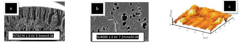
Figure 2 shows the FESEM and AFM micrographs of the modified PVDF hollow fiber membranes. Improvement of membrane morphology is observed for addition of a small amount of TiO2 nanoparticles. TiO2 nanoparticles have high specific areas and hydrophilicity, which will affect the mass transfer during the spinning process. The cross-sectional images for all hollow fibers consist of finger-like macrovoids extending from both inner and outer wall of the hollow fiber, and an intermediate sponge-like layer (Figs. 2a to 2b).
The membranes surface topographies of 3-D image was observed using AFM. The high peaks seen as bright regions in the AFM images characterize the nodules while the pores are seen as dark depressions. As shown in Figure 2c, the AFM images revealed that the surfaces of PVDF UF membranes have nodule-like structures and the nodule aggregates were formed at both inner and outer surface. The images further indicated that the membrane prepared from the dope containing TiO2 concentration of 1.95 wt.% (PT-10) had a smooth surface. Interfacial stresses working between the macromolecules and the TiO2 nanoparticles tend to enhance macromolecular orientation, particularly when TiO2 concentration is low, resulting in denser macromolecular packing and smoother surface. These results agree with Khayet and Matsuura (2001) studied with PVDF hollow fiber membranes [7] but disagree with Khulbe et al., studied with polyetherimide (PEI) hollow fiber membranes [24]. These different observations may be due to the difference in the polymer type and spinning conditions.
Figure 2. FESEM images of the (-a) cross section (Mag. 500x), (-b) outer surface (Mag. 40.0kx) and (-c) AFM image of PVDF UF membranes.
3.2 Effect of MLSS concentration and ABFR on membrane performance
The fouling rate under different specific MLSS concentrations in the feed wastewater is shown in Figure 3a. By comparing these findings with the results shown in Figure 3a, the great difference in the fluxes of wastewaters with MLSS concentration 3 and 4.5 g/L is obvious. It was observed that during experiments the flux for feed solution with MLSS concentration of 3 g/L becomes higher than that of 4 g/L. This fact suggests a higher tendency of suspended solids concentration to interact into membrane surface and also ability of air bubbling to enhanced the permeate flux. The flux values on submerged ultrafiltration for feed solution with increasing MLSS concentration become lower by 18 %. For both MLSS concentration, their foulings tend a quite different.
a
HITACHI 1.0 kV 9.3mmx5.0k SU8000 2.0 kV 7.2mmx50.0k
Figure 3. Effects of (-a) mixed liquor suspended solids concentration and (-b) different specific air bubble flow rates on permeate volume.
Generally, the increase of membrane fouling with increasing MLSS concentration was found in many literatures by several reseachers, but some other studies have revealed no effect of MLSS concentration on fouling up to a threshold concentration [25]. The impact of air bubbling used in submerged membrane system was investigated, in which the continuous air flow rate enhanced the membrane critical flux and thus minimized the fouling on the surface membrane. It is known that the membrane fouling can be considered from a critical flux point of view [26]. Figure 3b shows the trend in dP/dt for various air bubbles flow rate. Significant variation is observed in terms of membrane permeability recovery, as expressed byn the recovery factor of dP/dt calculated during the hysteresis loops of the type shown in Figure 3b. The results indicated that the use of air bubbles flow rate of 2.4 mL/min illustrated the increase of flux more than that of air bubbles flow rate of 1.2 and 3.0 mL/min. The degree supression of irreversible fouling was occured at air bubbles flow rate of 2.4 mL/min due to the achieved highest flux. Moreover, this would also mean that the aeration can be tuned according to the permeate flux to reduce the power consumption related to the air scouring.
The removal of main parameters of permeate for refinery produced wastewater treatment has been calculated and listed in table 4. These results were achieved by using refinery produced wastewater with MLSS concentration of 3 g/L and ABFR of 2.4 ml/min.
Table 4. Removal of the main parameters for refinery produced wastewater treatment
Parameter Removal of main parameters
Flux, L/m3h 148.82
TSS (%) 99.82
Sulfide (%) 89.2
4. CONCLUSIONS
The submerged ultrafiltration technique has been conducted to elucidate flux and fouling mechanism. PVDF UF membranes were fabricated via a dry-jet wet spinning method. Several characterizations and measurement techniques such as membrane structure, surface wettability, porosity, average pore size, and permeability were utilized to evaluate fine structural details of the membrane and membrane performance. Refinery produced wastewater filtration was conducted through in-house prepared PVDF hollow fiber ultrafiltration membranes. Permeability test results high flux of 148.82 L/m3h and removal of total suspended solids and sulfide of 99.82% and 89.2%, respectively of refinery produced wastewater treatment. This was concluded that LiCl.H2O and TiO2 nanoparticles affected the hydrophilic PVDF UF membranes performance remarkably.
REFERENCES
[1]. K..J. Howe, M.M. Clark, “Fouling of microfiltration and ultrafiltration membranes by natural waters”, Environ.Sci.Tech. vol 36, pp 3571-3576, 2002.
[2]. H. Huang, K. Schwab, J.G. Jacangelo, “Pretreatment for low pressure membranes in water treatment: a review”, Environ.Sci.Tech., vol 43, no. 9, pp 3011-3019, 2009.
[3]. X.J. Huang, Z.K. Xu, L.S. Wang, J.L. Wang, “Surface modification of polyacrylonitrile-based membranes by chemical reactions to generate phospholipid moieties”, Langmuir, vol 21, no. 7, pp. 2941-2947, 2005.
[4] T. Caroll, N.A. Booker, “Axial features in the fouling of hollow-fibre membranes”, J. Membr. Sci., vol 168, no.1-2, pp. 203-212, 2000. [5]. A.H. Nguyen, R.M. Narbaitz, T. Matsuura, ”Impacts of hydrophilic membrane additives on the ultrafiltration of river water”, J. Environ.
Eng., ASCE, vol 133, no. 5, pp. 515-522, 2007.
[6]. A. Bottino, G. Capanelli, S. Munari, A. Turturro, “High performance ultrafiltration membranes cast from LiCl doped solution”,
Desalination, vol. 68, pp. 167-177, 1998.
[7]. M. Khayet, T. Matsuura, “Preparation and characterization of polyvinylidene fluoride membranes for membrane distillation”, Ind. Eng. Chem. Res., vol. 40, pp. 5710-5718, 2001.
[8]. A. Bottino, G. Capannelli, A. Comite, R. Mangano, “Critical flux in submerged membrane bioreactors for municipal wastewater treatment”, Desalination, vol., 245, pp. 748-753, 2009.
[9]. B. Bienati, A. Bottino, G. Cappanelli, A. Comite, “Characterization and performance of different types of hollow fibre membranes in a laboratory-scale MBR for the treatment of industrial wastewater”, Desalination, vol. 231, pp. 133-140, 2008.
[10]. S. Chabot, C. Roy, G. Chowdhury, T. Matsuura, “Development of poly(vinylidene fluoride) hollow fiber membranes for the treatment of water/organic vapor mixtures”, J. Apply. Polym. Sci., vol. 65, pp. 1263-1270, 1997.
[11]. Cao, X., Ma, J., Shi, X., Ren, Z., “Effect of TiO2 nanoparticle size on the performance of PVDF membrane”,Appl. Surf. Sci., vol. 253, pp.
2003-2010, 2006.
[12]. E. Yuliwati, A.F. Ismail, T. Matsuura, M.A. Kassim, M.S. Abdullah, “Characterization of surface-modified porous PVDF hollow fibers for refinery wastewater treatment using microscopic observation”, Desalination, vol. 283, pp. 206-213, 2011.
[13]. E. Yuliwati, A.F. Ismail, “Effect of additives concentration on the surface properties and performance of PVDF ultrafiltration membranes for refinery produced wastewater treatmen”, Desalination, vol. 273, pp. 226-234, 2011.
[14]. Environmental Quality (Industrial Effluent) Regulation 2009, http://www.mkma.org/Environmental Regulation2009.htm., Retrieved on 25 May 2011.
[15]. E. Yuliwati, A.F. Ismail, T. Matsuura, M.A. Kassim, M.S. Abdullah, “Effect of modified PVDF hollow fiber submerged ultrafiltration membrane for refinery wastewater treatment”,Desalination, vol. 283, pp. 214-220, 2011.
[16]. M. Khayet, C.Y. Feng, K.C. Khulbe, T. Matsuura, “Preparation and characterization of polyvinylidene fluoride hollow fiber membranes for ultrafiltration”, Polymer, vol. 43, pp. 1917-1935, 2002.
[17]. Y.H. Zhao, Y.L. Qian, B.K. Zhu, Y.Y. Xu, “Modification of porous poly(vinylidene fluoride) membrane using amphiphilic polymers with different structures in phase inversion process”, J. Membr. Sci., vol. 310, no. 1-2, pp. 567-576, 2008
[18]. B. Van der Bruggen, C. Vandecasteele, T. van Gestel, W. Doyen, R. Leysen, ”A review of pressure-driven membrane processes in wastewater treatment and drinking water production”, Environ. Prog., vol. 22, no. 1, pp.46-56, 2003.
[19]. F. Wang, V.V. Barbara, “Pore blocking mechanism during early stages of membrane fouling by colloids”, J. Colloid Inter. Sci., vol. 328, no. 2, pp. 464-469, 2008.
[20]. H. Yamamura, K. Kimura, T. Okajima, H. Tokumoto, Y. Watanabe, “Affinity of functional groups for membrane surfaces: implications for physically irreversible fouling”, Environ. Sci. Tech., vol. 42, no. 14, pp. 5310-5315, 2008.
[21]. A.W. Zularisam, A.F. Ismail, R. Salim, “Behaviour of natural organic matter in membrane filtration for surface water treatment: a-review”, Desalination, vol. 194, pp. 211-231, 2006.
[21]. S.S. Sablani, M.F.A. Goosen, R. Al-Belushi, M. Wilf, “Concentration polarization in ultrafiltration and reverse osmosis: a critical review”, Desalination, vol. 141, pp.269-289, 2001.
[22]. S.J. Oh, N. Kim, Y. T. Lee, “Preparation and characterization of PVDF/TiO2 organic-inorganic composite membranes for fouling
resistance improvement”, J. Membr. Sci., vol., 345, pp. 13-20, 2009.
[23]. G.D. Profio, X. Ji, E. Curcio, E., Drioli, “Submerged hollow fiber ultrafiltration as seawater pretreatment in the logic of integrated membrane desalination systems”, Desalination, vol. 269, pp. 128-135, 2011.
[24]. K.C. Khulbe, C.Y. Feng, F. Hamad, T. Matsuura, M. Khayet, “Structural and performance study of microporous polyetherimide hollow fiber membranes prepared at different air gap”, J. Membr. Sci., vol. 245, pp. 191-198, 2004.
[25]. P. Le-Clech, B. Jefferson, S.J. Judd, “Impact of aeration, solid concentration and membrane characteristics on the hydraulic performance of a membrane bioreactor”, J. Membr. Sci., vol. 218, pp. 117-129, 2003.
[26]. Y. Mo, J. Chen, W. Xue, X. Huang, “Chemical cleaning of nanofiltration membrane filtrating the effluent from a membrane bioreactor”,
![Table 1: Composition of synthetic refinery wastewater with standard deviation (S.D.) and Standard B of national standard for wastewater and water discharged [14]](https://thumb-ap.123doks.com/thumbv2/123dok/2901029.1698775/2.612.143.467.595.657/composition-synthetic-refinery-wastewater-deviation-standard-wastewater-discharged.webp)