THE PERFORMANCE IMPROVEMENT of FIBER PULL-OUT of NYLON 600
by CLUMPED EMBEDDED FIBER END
M.I. Retno Susilorini1) 1)
Lecturer, Unika Soegijapranata, Semarang E-mail :[email protected]
ABSTRACT: The fiber pull-out is an effort to characterize the fiber-cementitious matrix interface that becomes a basis for fiber reinforced cementitious composites design. Obviously, the fiber performance is influenced by embedded fiber end condition, especially for synthetic fiber such as nylon. The surface of nylon is very smooth and slippery that causes the low bond stress between fiber-cementitious matrix interface. Therefore, a strong effort to improve better fiber performance is very important to be done by implementing special treatment for embedded fiber end condition. The research purposes to show the performance improvement of nylon fiber by fiber pull-out experimental test and modeling. Fiber pull-out experimental test used fiber pullout specimens with fiber of nylon 600 made in Indonesia, 1.1 mm in diameter, and fiber embedded length lf of 100
mm, and also vary with clumped and straight embedded fiber end condition. The clumped embedded fiber end condition was made by burning the end of fiber until the fiber’s end change into clumped form. The modeling of fiber pull-out with clumped embedded fiber end is an improvement of Susilorini’s previous model of straight embedded fiber end that is conducted analytically. The experimental and theoretical model has shown that all type of specimens were broken. Better performance shown by clumped embedded fiber end specimens that were reaching loads of 14-35% higher than straight embedded fiber end specimens, about 1200-1400 N. The research met conclusions of several theoriesthat: (a) The clumped embedded fiber end condition generates higher shear-friction stress τ to against the fiber tension load will improve the specimen’s pull-out load; (b) During the crack Δx formation to left side direction, the shear-friction τ along the embedded fiber gives contribution to against the displacement of fiber free-end; (c) The higher bond capacity σm is, the higher shear-friction stress τ will be; (d) The length of stable crack is determined by the position of crack arrester; (e) A new equation derived for load Pn for a model for fiber pull-out of nylon 600 with clumped embedded fiber end; and (f) The
clumped embedded fiber end improves the pull-out load of nylon 600 fiber pull-out specimens.
KEYWORDS: pull-out, fiber, nylon, bond, clumped, model, pull-out load, shear-friction stress
1. INTRODUCTION
Fiber takes an important role in determining whole fiber-reinforced cementitious composite (FRC) performance. The fiber existence shows many advantages of crack delaying and resisting (Naaman, et.al,1991). In FRC, the interface behavior between fiber and matrix will be predicted by pull out tests. According to Sun and Lin (2001), the study of fiber-matrix interface is mainly to make certain about composites properties, to select the major ingredients of composites, and to predict the failure of composites. The using of synthetic fibers in FRC generates significant added values, that are strain-hardening property (Susilorini, 2007), higher tension strength, elastic modulus, and various fiber surfaces (Li, Chan, and Wu, 1994), high performance as alike steel performance (Clements, 2002), and even higher compressive stress for fiber concrete that its nylon fibers are irradiated by gamma (Martinez-Barera, 2006).
et al. (2000a, b) used flexural beam and cylinder fiber concrete specimens with straight and clumped short fibers and found that flexural and splitting tensile strength of nylon fiber concrete is higher than the plain concrete. It was also investigated by Suseno, et, al, (2000a,b) that wider crack width is found on plain concrete. Susilorini (2007) established pull-out model using pull-out and fracture specimens with straight fibers that established many theories of unstable and stable cracks, the presence of crack arrester, equations for bond capacity σm and Poisson’s ration of fiber relation, fiber stress σs and matrix stress σm relation at the time of failure, stable crack length, load for out and fracture pull-out models, determination of bond capacity by using stable crack, existing of slip stage and strain-hardening stage, and also the possibility of crack arrester presence.
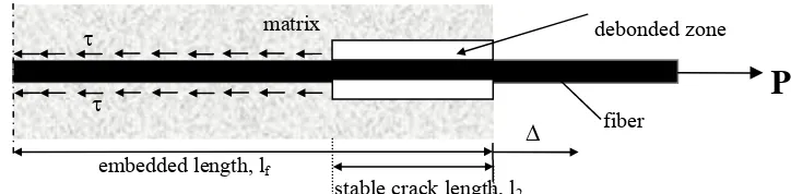
Figure 1 Pull-out Problem Decription
The fiber pull-out is an effort to characterize the fiber-cementitious matrix interface that becomes a basis for fiber reinforced cementitious composites design. A description of pull-out problem is shown by Figure 1. In that figure, a tension load P is applied to fiber free end of a pull-out specimen. The applied load causes displacement of free end fiber of Δ. Some parts of the fiber are debonded from the cementitious matrix called debodend zone. The debonded zone then named stable crack length l2 that
created by fracture process during pull-out. It is difficult to determine stable crack length; however the crack length is formulated very well by Susilorini (2007). In general, previous pull-out models were built to represent the pull-out process, they are analytical models, fracture mechanic’s based models, and micro-fractural models (Wang, Li, Backer, 1988a, b; Li, Stang, 1987; Morrison, Shah, Jenq, 1988; Kim, Zhou, Mai, 1992; Li, Chan, 1994; Sumitro, Tsubaki, 1997; Naaman, et.al. (1990); and Bentur, et.al. (1996). Some of those models used steel fiber, implemented shear stress and friction shear stress along the fiber, and neglected the Poisson’s ratio. Among the previous models, there is no approach of stable crack length in the matrix but Susilorini’s model (2007). Some of the models applied shear and friction-shear stress along the debonded zone. Those facts are contrary with Susilorini’s previous theory which states that nylon fiber surface is slippery so that is shear established along the debonded fiber on the pull-out process (the establishment is along the embedded fiber so that the fiber and matrix are still in composite condition).
It was established by Susilorini (20070 that nylon fiber which is pulled out of the cementitious matrix will meet ‘jagged’ strain-hardening characteristic before it was broken. It is understood that the slippery property of nylon fiber has become an obstacle in reaching high pull-out load or stress. To reach higher pull-out load, it is important to apply clumped fiber end condition to generate shear-friction stress that also means bond property enrichment. It can be said that this paper want to deliver a model development of previous Susilorini’s pull-out model (2007), that is a model for fiber pull-out of nylon 600 with clumped embedded fiber end. This research definitely purposes to show the performance improvement of nylon fiber by fiber pull-out experimental test and modeling.
2. METHODS
The research conducted two methods to reach final conclusions, experiment method and analytical method which are explained as follow. The experiment method applied pull-out test with specimens described by Figure 2 and set up of the pull-out test by Figure 3. This research used nylon 600 fiber local made (“Golden Fish” brand) with 1.1. mm in diameter and embedded length of 100 mm, several specimens use straight embedded fiber end and others use the clumped one. The clumped embedded fiber end condition was made by burning the end of fiber until the fiber end change into clumped form. Mix design for cementitious matrix is cement : sand : water ratio of 1:1:0.6. Analytical method applied by theoretical modeling that produces formulation. The model is a development model of
P
debonded zone
fiber
embedded length, lf
stable crack length, l2 Δ
matrix
τ
previous model (Susilorini, 2007) for fiber pull-out of nylon 600 pull-out with clumped embedded fiber end. The improved theoretical model then compared to experimental results.
Figure 1 Dimensions of Pull-Out Specimen with Clumped Embedded Fiber End
Figure 2 Pull-Out Test Set-Up
3. RESULT, MODELING, AND DISCUSSION
Result
0 200 400 600 800 1000 1200 1400 1600
0 20 40 60 80 100 120
DISPLACEMENT (mm)
LO
A
D
(N
)
1036
1037 1035
2380
2382 2381
Figure 3 The Results of Pull-Out Test with Straight and Clumped Fiber End
The experiments observed that nylon fiber has had average maximum tension stress of 1471.21 MPa, average maximum strain of 0.89, average maximum elongation of 84.11%, and average maximum tension load of 1398.13 N. A unique property of nylon fiber is shown by ‘jagged’ phenomenon on its load-displacement (P-δ) and stress-strain (σ−ε) curves that are caused by the ‘yield point elongation’ and the viscosity of nylon itself. For critical Poisson’s ratio of fiber ofν=0.47, the critical strain of
specimen width = 20 mm
fixed part length, 150 mm
70 mm
specimen length, l1 = 250 mm
fixed part length, 150 mm fiber outer length, 30 mm
embedded length, 100 mm
clumped embedded fiber end
pull-out specimen
Lower crosshead Nut Nut
Upper crosshead
nylon will reach ε=0.29. The results of pull-out test noted that both pull-out specimens with straight embedded fiber end and clumped ones showed several stages existence (Figure 3): (a) Pre-slip stage, (b) slip stage, and (c) Strain-hardening stage. The pull-out test results with straight fiber end (Figure 3) found pre-slip loads are about 400-430 N and pre-slip displacements of no more than 0.1 mm. The slip loads have been found in the same range of pre-slip loads with displacements of 3-30 mm. The strain-hardening loads are observed as 900-1200 N as regard. For pull-out test with clumped fiber end (Figure 3), pre-slip loads are ranged about 400-430 N with pre-slip displacements of no more than 0.1 mm. The slip loads had the same range of pre-slip loads with displacements of 3-30 mm. The strain-hardening loads are found higher than pull-out test with straight fiber end, which are about 1200-1400 N.
Modeling
A pull-out model has been derived by Susilorini (2007) for straight embedded fiber end. In this research, the previous model is improved for clumped embedded fiber end. This improved model considered many following aspects: (1) Fracture capacity of embedded fiber is a function of Poisson’s ratio of fiber, (2) Some stages exist during the pull-out and fracture pull-out process, (4) A ‘jagged’ phenomenon exists on strain-hardening part of load-displacement (P-δ) and stress-strain (σ−ε) curves of pull-out, and (4) Unstable and stable fracture process phenomenon exist during the pull-out process.
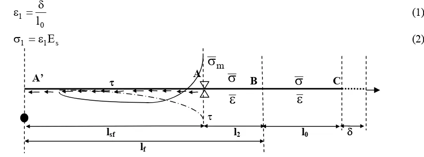
Figure 4 Pull-Out Model with Clumped Embedded Fiber End at Elastic Stage
Figure 4 shows a piece of embedded fiber (A’A) with clumped embedded fiber end at A’ which is constrained at A and B but free at C. Free end fiber length named l0 and embedded fiber end called lf.
A displacement δ is applied at C and both cementitious matrix and fiber are still in composites condition. The displacement δ will emerge matrix stress σm. The clumped fiber end will also generate the shear-friction stress τ existence along the fiber-matrix interface. The value of matrix stress σm increases until σm =σm =σm
( )
ν .The value of critical matrix stress σm is a bond capacity at the time of crack which represents the ultimate fracture tension capacity. Thus, the strain and stress at BC will be:0 1
l
δ
=
ε
(1)s 1 1
=
ε
E
σ
(2)Figure 5 Pull-Out Model with Clumped Embedded Fiber End atUnstable Fracture Process
When displacement δ keep growing, then a crack will be formed. This crack emerges unstable fracture process. After a crack formed, the stress of the composite then being transferred to the fiber. By crack
A
B C
l2 l0 δ
lf
m
σ
σ
ε
σ
ε
A’τ τ
lsf
A B C
l0 δ
lf
σm
σ1
ε1
A’
formation, unstable fracture process phenomenon will release the constraint at B (Figure 5). The crack length is growing to be as long as l2 and constraint at A still can remove to left side. When the crack
length l2 is longer than embedded length lf, fiber may be pulled-out. The shear-friction stress τ is
distributed along A’A, and then the length of shear-friction is called lsf. The higher bond capacity is,
the higher shear-friction will be.
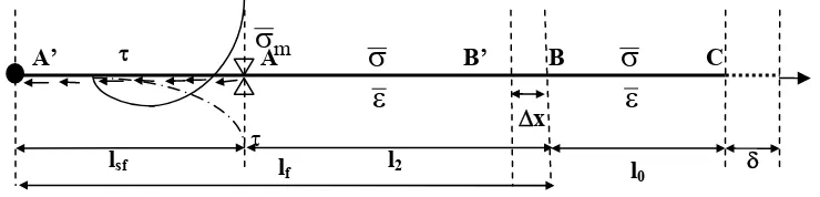
Figure 6 Pull-Out Model with Clumped Embedded Fiber End atStable Fracture Process
An unstable fracture process may go the stable fracture process which is explained as follow. Assume that a crack formed as (Figure 6), then the increasing of displacement δ will also increase strain ε1 and stress σ1 at B’B. Those strain ε1 and stress σ1 increasing will cause the achieving critical value of matrix stress σm and strain
ε
. Therefore, the displacement δ increasing repeated at B’ at the same time a new crack of another formed Δx at the left side of fiber. During the crack Δx formation, the shear-friction τ gives contribution along the embedded fiber to against the displacement of fiber free-end. It happened continuously until constraint A is fixed. The constraint A becomes crack arrester which prevents crack growing. In this situation the crack will be stopped to grow and crack length remains l2. Once stable crack length l2 achieved, then strain at l0 part transfer to l2 part. The stress andThe stable crack is formulated as:
ε
Formulation of the theoretical model is defined by equation (8). The model will result a P-δ (load-displacement) curve (Figure 7) that consists of 3 (three) stages: (a) Stage of pre-slip, (2) Stage of slip, and (3) Stage of strain-hardening. During the stage of pre-slip, cracks have not been created, so that the fracture process phenomenon not exists. After critical matrix stress σm exceeded, a crack is formed, the stage of slip and unstable fracture process has just begun. The type of fracture in this stage is lateral fracture. The unstable fracture process keeps going and crack length increases until stable crack length l2 reached at the end of stage of slip. Whenever the stable crack length l2 achieved, the
unstable fracture process changed to stable fracture process. The stable fracture process is going to be continued by the stage of strain-hardening, while ‘a jagged’ phenomenon caused by nylon multiple constrictions. In this stage, the increase of the strain ε will increase the stress σ until the fiber is broken. The clumped embedded fiber end condition generates higher shear-friction stress τ to against the fiber tension load will improve the specimen’s pull-out load.
Figure 7 P-δ (load-displacement) Relation of Theoretical Pull-Out Model
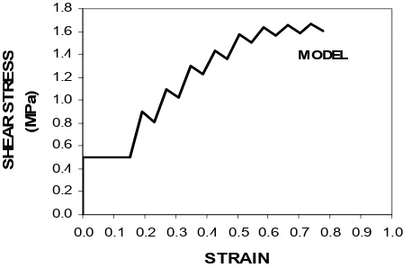
model above has compared to experimental results. The P-δ (load-displacement) curves and σ-ε (fiber stress-strain) curve (Figure 8) and also the τ-ε (shear-friction stress-strain) curve (Figure 9) described as follow.
Figure 8 P-δ and σ−ε Relations of Model and Experimental Results
Discussion
Figure 8 shows that the model fit to the experimental results. The maximum strain of both model and experimental results (0.8) are lower than maximum strain of nylon fiber tension test (0.89). It is found that the pull-out load of clumped fiber end specimens is 14-35% higher than the pull-out load of straight embedded fiber end specimens. The reason of lower strain and the pull-out load improvement is because of the clumped embedded fiber end condition generates higher shear-friction stress τ to against the fiber tension load will improve the specimen’s pull-out load. It should be noted that during the crack Δx formation to left side direction, the shear-friction τ distributedalong the embedded fiber gives contribution to against the displacement of fiber free-end. A τ-ε (shear-friction stress-strain) curve is described by Figure 9. Thus, the higher bond capacity σm is, the higher shear-friction stress τ will be.
4. CONCLUSIONS
Several theories have been established by this research:
a) The clumped embedded fiber end condition generates higher shear-friction stress τ to against the fiber tension load will improve the specimen’s pull-out load
b) During the crack Δx formation to left side direction, the shear-friction τ along the embedded fiber gives contribution to against the displacement of fiber free-end
c) The higher bond capacity σm is, the higher shear-friction stress τ will be d) The length of stable crack is determined by the position of crack arrester
e) A new equation derived for load Pn for a model for fiber pull-out of nylon 600 with clumped
embedded fiber end
f) The clumped embedded fiber end improves the pull-out load of nylon 600 fiber pull-out specimens
5. ACKNOWLEDGMENTS
The authors gratefully acknowledge UBCHEA (United Board of Higher Christian Education) for supporting research grant (2005-2007), Prof. Ir. Moh. Sahari Besari, MSc., PhD., and Prof. Bambang Suryoatmono, PhD., for their great contributions of ideas, discussions, and intensive assistance during my Doctoral Study at Parahyangan Catholic University.
NOTATION
A fiber section area (mm2) Afl fiber surface area (mm2)
Am matrix surface area (mm2)
D fiber diameter (mm)
En, Epr modulus of elasticity at stage of strain-hardening (MPa)
Eps modulus of elasticity at stage of pre-slip (MPa)
Es modulus of elasticity at stage of slip (MPa)
P, Pn tension load (N)
a1 total displacement of a stage (mm)
a2 initial length of specimen or fiber that is specific for every stage (mm)
b specimen width (mm)
rΔI ratio of total free-end fiber displacement of free-end at stage of pre-slip
rΔII ratio of total free-end fiber displacement of free-end at stage of slip
rΔIII ratio of total free-end fiber displacement of free-end at stage of strain-hardening
l0 initial outer fiber length (mm)
l2 stable crack length (mm)
lf embedded fiber length (mm)
lsf length of shear-friction (mm)
Δi free-end displacement for n at stage of strain-hardening (mm) σ1 fiber stressat the midldle of right side of matrix (MPa)
2
l
σ
fiber stress at l2 part when stable crack length achieved (MPa)REFERENCES
Avarett, RD (2004). “Fracture Mechanics of High Performance Nylon Fibers”, Thesis, Georgia Institute of Technology, USA.
Bentur, A., Wu, S.T., Banthia, N., Baggott, R., Hansen, W., Katz, W., Leung, C.K.Y, Li, V.C., Mobasher, B., Naaman, A.E., Robertson, R., Soroushian, P., Stang, H., Taerwe, L.R. (1996). “Fiber-Matrix Interfaces”, High Performance Fiber Reinforced Cement Composites 2, (eds. Naaman, A.E., Reindhardt, H.W.), E&FN Spons, London, pp. 149-191.
Clements, M. (2002). “Synthetic as Concrete Reinforcement”, Concrete Magazine, United Kingdom, September, pp. 37-38.
Li, V.C., Chan, Y.W. (1994). “Determination of Interfacial Debond Mode for Fiber Reinforced Cementitious Composites”, Journal of Engineering Mechanics,ASCE, Vol. 120, No. 4, April, pp. 707-719.
Li, V.C., Chan, Y.W., Wu, H.C. (1994). “Interface Strengthening Mechanism in Polymeric Fiber Reinforced Cementitious Composites”, Proceedings of International Symposium on Brittle Matrix Composites, (eds. Brandt, A.M, Li, V.C., Marshall, L.H), IKE and Woodhead Publ, Warsaw, pp. 7-16.
Li, V.C., Stang, H. (1997). “Interface Property Characterization and Strengthening Mechanism in Fiber Reinforced Cement Based Composites”, (Review Arcticle), Journal of Advanced Cement Based Materials, Vol. 6, pp. 1-20.
Martinez-Barrera, G (2006). “Concrete Reinforce with Irradiated Nylon Fibers”, Journal of Material Research, Vol.21, No. 2, February, pp. 484-491.
Morisson, J.K., Shah, S.P., Jenq, Y.S. (1988). “Analysis of Fiber Debonding and Pull-out in Composites”, Journal of Engineering Mechanics, ASCE, Vol. 114, No. 2, February, pp. 277-294.
Naaman, AE., Namur, GG., Alwan, JM., Najm, HS. (1990). “Fiber Pullout and Bond Slip. I: Analytical Study”, Journal of Structural Engineering, ASCE, vol. 117, No. 9, pp. 2769-2790. Nadai, A. (1950). “Theory of Flow and Fracture of Solids”, Volume I, McGraw-Hill Company. Inc,
New York, USA.
Sumitro, S., Tsubaki, T. (1998). “Microfractural Pullout Model of Steel Fiber Reinforced Concrete”, Proceedings Framcos-3, AEDIFICATIO Publishers, Freiburg, Germany, pp. -. Sun, W., Lin, F. (2001). “Computer Modelling and FEA Simulation for Composite Single Fiber
Pullout”, Journal of Thermoplastic Composite Materials, Vol. 14, No. 4, pp. 327-343. Suseno, W., Saptono, K., Yosephine, P., Andre, S. (2000a). “Pengaruh Fiber Senar Pancing
Terhadap Kuat Lentur Beton”, Jurnal Sipil Supra, Vol. 2, No. 4, April-Juni , pp. 116-124. Suseno, W., Saptono, K., Sapthina, M., Wibowo, M. (2000b). “Uji Tarik Belah pada Beton Serat
dengan Senar Pancing”, Jurnal Sipil Supra, Vol. 2, No. 6, Oktober-Desember, pp. 238-247. Susilorini, R. (2007). “Model Masalah Cabut-Serat Nylon 600 Tertanam dalam Matriks
Sementitis yang Mengalami Fraktur”, Dissertation, Parahyangan Catholic University, Bandung.
Wang, Y., Li, V.C., Backer, S. (1988a). “Analysis of Synthetic Fiber Pull-out from a Cement Matrix”, (eds. Mindess, S., Shah, S.P), Proceedings of Material Research Society Symposium, Vol. 114, Pittsburgh, pp. 159-165.