H.264 and MPEG-4 Video
Compression
Video Coding for Next-generation Multimedia
CopyrightC2003 John Wiley & Sons Ltd, The Atrium, Southern Gate, Chichester, West Sussex PO19 8SQ, England
Telephone (+44) 1243 779777
Email (for orders and customer service enquiries): [email protected] Visit our Home Page on www.wileyeurope.com or www.wiley.com
All Rights Reserved. No part of this publication may be reproduced, stored in a retrieval system or transmitted in any form or by any means, electronic, mechanical, photocopying, recording, scanning or otherwise, except under the terms of the Copyright, Designs and Patents Act 1988 or under the terms of a licence issued by the Copyright Licensing Agency Ltd, 90 Tottenham Court Road, London W1T 4LP, UK, without the permission in writing of the Publisher. Requests to the Publisher should be addressed to the Permissions Department, John Wiley & Sons Ltd, The Atrium, Southern Gate, Chichester, West Sussex PO19 8SQ, England, or emailed to [email protected], or faxed to (+44) 1243 770620.
This publication is designed to provide accurate and authoritative information in regard to the subject matter covered. It is sold on the understanding that the Publisher is not engaged in rendering professional services. If professional advice or other expert assistance is required, the services of a competent professional should be sought.
Other Wiley Editorial Offices
John Wiley & Sons Inc., 111 River Street, Hoboken, NJ 07030, USA Jossey-Bass, 989 Market Street, San Francisco, CA 94103-1741, USA Wiley-VCH Verlag GmbH, Boschstr. 12, D-69469 Weinheim, Germany
John Wiley & Sons Australia Ltd, 33 Park Road, Milton, Queensland 4064, Australia
John Wiley & Sons (Asia) Pte Ltd, 2 Clementi Loop #02-01, Jin Xing Distripark, Singapore 129809 John Wiley & Sons Canada Ltd, 22 Worcester Road, Etobicoke, Ontario, Canada M9W 1L1 Wiley also publishes its books in a variety of electronic formats. Some content that appears in print may not be available in electronic books.
British Library Cataloguing in Publication Data
A catalogue record for this book is available from the British Library ISBN 0-470-84837-5
Typeset in 10/12pt Times roman by TechBooks, New Delhi, India
Printed and bound in Great Britain by Antony Rowe, Chippenham, Wiltshire
Contents
About the Author xiii
Foreword xv
Preface xix
Glossary xxi
1 Introduction 1
1.1 The Scene 1
1.2 Video Compression 3
1.3 MPEG-4 and H.264 5
1.4 This Book 6
1.5 References 7
2 Video Formats and Quality 9
2.1 Introduction 9
2.2 Natural Video Scenes 9
2.3 Capture 10
2.3.1 Spatial Sampling 11
2.3.2 Temporal Sampling 11
2.3.3 Frames and Fields 13
2.4 Colour Spaces 13
2.4.1 RGB 14
2.4.2 YCbCr 15
2.4.3 YCbCr Sampling Formats 17
2.5 Video Formats 19
2.6 Quality 20
2.6.1 Subjective Quality Measurement 21
2.6.2 Objective Quality Measurement 22
2.7 Conclusions 24
CONTENTS
•
viii3 Video Coding Concepts 27
3.1 Introduction 27
3.2 Video CODEC 28
3.3 Temporal Model 30
3.3.1 Prediction from the Previous Video Frame 30
3.3.2 Changes due to Motion 30
3.3.3 Block-based Motion Estimation and Compensation 32
3.3.4 Motion Compensated Prediction of a Macroblock 33
3.3.5 Motion Compensation Block Size 34
3.3.6 Sub-pixel Motion Compensation 37
3.3.7 Region-based Motion Compensation 41
3.4 Image model 42
3.4.1 Predictive Image Coding 44
3.4.2 Transform Coding 45
3.4.3 Quantisation 51
3.4.4 Reordering and Zero Encoding 56
3.5 Entropy Coder 61
3.5.1 Predictive Coding 61
3.5.2 Variable-length Coding 62
3.5.3 Arithmetic Coding 69
3.6 The Hybrid DPCM/DCT Video CODEC Model 72
3.7 Conclusions 82
3.8 References 83
4 The MPEG-4 and H.264 Standards 85
4.1 Introduction 85
4.2 Developing the Standards 85
4.2.1 ISO MPEG 86
4.2.2 ITU-T VCEG 87
4.2.3 JVT 87
4.2.4 Development History 88
4.2.5 Deciding the Content of the Standards 88
4.3 Using the Standards 89
4.3.1 What the Standards Cover 90
4.3.2 Decoding the Standards 90
4.3.3 Conforming to the Standards 91
4.4 Overview of MPEG-4 Visual/Part 2 92
4.5 Overview of H.264 / MPEG-4 Part 10 93
4.6 Comparison of MPEG-4 Visual and H.264 94
4.7 Related Standards 95
4.7.1 JPEG and JPEG2000 95
4.7.2 MPEG-1 and MPEG-2 95
4.7.3 H.261 and H.263 96
4.7.4 Other Parts of MPEG-4 97
4.8 Conclusions 97
CONTENTS
•
ix5 MPEG-4 Visual 99
5.1 Introduction 99
5.2 Overview of MPEG-4 Visual (Natural Video Coding) 100
5.2.1 Features 100
5.2.2 Tools, Objects, Profiles and Levels 100
5.2.3 Video Objects 103
5.3 Coding Rectangular Frames 104
5.3.1 Input and Output Video Format 106
5.3.2 The Simple Profile 106
5.3.3 The Advanced Simple Profile 115
5.3.4 The Advanced Real Time Simple Profile 121
5.4 Coding Arbitrary-shaped Regions 122
5.4.1 The Core Profile 124
5.4.2 The Main Profile 133
5.4.3 The Advanced Coding Efficiency Profile 138
5.4.4 The N-bit Profile 141
5.5 Scalable Video Coding 142
5.5.1 Spatial Scalability 142
5.5.2 Temporal Scalability 144
5.5.3 Fine Granular Scalability 145
5.5.4 The Simple Scalable Profile 148
5.5.5 The Core Scalable Profile 148
5.5.6 The Fine Granular Scalability Profile 149
5.6 Texture Coding 149
5.6.1 The Scalable Texture Profile 152
5.6.2 The Advanced Scalable Texture Profile 152
5.7 Coding Studio-quality Video 153
5.7.1 The Simple Studio Profile 153
5.7.2 The Core Studio Profile 155
5.8 Coding Synthetic Visual Scenes 155
5.8.1 Animated 2D and 3D Mesh Coding 155
5.8.2 Face and Body Animation 156
5.9 Conclusions 156
5.10 References 156
6 H.264/MPEG-4 Part 10 159
6.1 Introduction 159
6.1.1 Terminology 159
6.2 The H.264 CODEC 160
6.3 H.264 structure 162
6.3.1 Profiles and Levels 162
6.3.2 Video Format 162
6.3.3 Coded Data Format 163
6.3.4 Reference Pictures 163
6.3.5 Slices 164
CONTENTS
•
x6.4 The Baseline Profile 165
6.4.1 Overview 165
6.4.2 Reference Picture Management 166
6.4.3 Slices 167
6.4.4 Macroblock Prediction 169
6.4.5 Inter Prediction 170
6.4.6 Intra Prediction 177
6.4.7 Deblocking Filter 184
6.4.8 Transform and Quantisation 187
6.4.9 4×4 Luma DC Coefficient Transform and Quantisation
(16×16 Intra-mode Only) 194
6.4.10 2×2 Chroma DC Coefficient Transform and Quantisation 195 6.4.11 The Complete Transform, Quantisation, Rescaling and Inverse
Transform Process 196
6.4.12 Reordering 198
6.4.13 Entropy Coding 198
6.5 The Main Profile 207
6.5.1 B Slices 207
6.5.2 Weighted Prediction 211
6.5.3 Interlaced Video 212
6.5.4 Context-based Adaptive Binary Arithmetic Coding (CABAC) 212
6.6 The Extended Profile 216
6.6.1 SP and SI slices 216
6.6.2 Data Partitioned Slices 220
6.7 Transport of H.264 220
6.8 Conclusions 222
6.9 References 222
7 Design and Performance 225
7.1 Introduction 225
7.2 Functional Design 225
7.2.1 Segmentation 226
7.2.2 Motion Estimation 226
7.2.3 DCT/IDCT 234
7.2.4 Wavelet Transform 238
7.2.5 Quantise/Rescale 238
7.2.6 Entropy Coding 238
7.3 Input and Output 241
7.3.1 Interfacing 241
7.3.2 Pre-processing 242
7.3.3 Post-processing 243
7.4 Performance 246
7.4.1 Criteria 246
7.4.2 Subjective Performance 247
CONTENTS
•
xi7.4.4 Computational Performance 254
7.4.5 Performance Optimisation 255
7.5 Rate control 256
7.6 Transport and Storage 262
7.6.1 Transport Mechanisms 262
7.6.2 File Formats 263
7.6.3 Coding and Transport Issues 264
7.7 Conclusions 265
7.8 References 265
8 Applications and Directions 269
8.1 Introduction 269
8.2 Applications 269
8.3 Platforms 270
8.4 Choosing a CODEC 270
8.5 Commercial issues 272
8.5.1 Open Standards? 273
8.5.2 Licensing MPEG-4 Visual and H.264 274
8.5.3 Capturing the Market 274
8.6 Future Directions 275
8.7 Conclusions 276
8.8 References 276
Bibliography 277
About the Author
Foreword
Work on the emerging “Advanced Video Coding” standard now known as ITU-T Recom-mendation H.264 and as ISO/IEC 14496 (MPEG-4) Part 10 has dominated the video coding standardization community for roughly the past three years. The work has been stimulating, intense, dynamic, and all consuming for those of us most deeply involved in its design. The time has arrived to see what has been accomplished.
Although not a direct participant, Dr Richardson was able to develop a high-quality, up-to-date, introductory description and analysis of the new standard. The timeliness of this book is remarkable, as the standard itself has only just been completed.
The new H.264/AVC standard is designed to provide a technical solution appropriate for a broad range of applications, including:
r
Broadcast over cable, satellite, cable modem, DSL, terrestrial.r
Interactive or serial storage on optical and magnetic storage devices, DVD, etc.r
Conversational services over ISDN, Ethernet, LAN, DSL, wireless and mobile networks, modems.r
Video-on-demand or multimedia streaming services over cable modem, DSL, ISDN, LAN, wireless networks.r
Multimedia messaging services over DSL, ISDN.Foreword
•
xviIn the work on the new H.264/AVC standard, a number of relatively new technical developments have been adopted. For increased coding efficiency, these include improved prediction design aspects as follows:
r
Variable block-size motion compensation with small block sizes,r
Quarter-sample accuracy for motion compensation,r
Motion vectors over picture boundaries,r
Multiple reference picture motion compensation,r
Decoupling of referencing order from display order,r
Decoupling of picture representation methods from the ability to use a picture for reference,r
Weighted prediction,r
Improved “skipped” and “direct” motion inference,r
Directional spatial prediction for intra coding, andr
In-the-loop deblocking filtering.In addition to improved prediction methods, other aspects of the design were also enhanced for improved coding efficiency, including:
r
Small block-size transform,r
Hierarchical block transform,r
Short word-length transform,r
Exact-match transform,r
Arithmetic entropy coding, andr
Context-adaptive entropy coding.And for robustness to data errors/losses and flexibility for operation over a variety of network environments, some key design aspects include:
r
Parameter set structure,r
NAL unit syntax structure,r
Flexible slice size,r
Flexible macroblock ordering,r
Arbitrary slice ordering,r
Redundant pictures,r
Data partitioning, andr
SP/SI synchronization switching pictures.Foreword
•
xviiMost people first learn about a standard in publications other than the standard itself. My personal belief is that if you want to know about a standard, you should also obtain a copy of it, read it, and refer to that document alone as the ultimate authority on its content, its boundaries, and its capabilities. No tutorial or overview presentation will provide all of the insights that can be obtained from careful analysis of the standard itself.
At the same time, no standardized specification document (at least for video coding), can be a complete substitute for a good technical book on the subject. Standards specifications are written primarily to be precise, consistent, complete, and correct and not to be particularly readable. Standards tend to leave out information that is notabsolutelynecessary to comply with them. Many people find it surprising, for example, that video coding standards say almost nothing about how an encoder works or how one should be designed. In fact an encoder is essentially allowed to do anything that produces bits that can be correctly decoded, regardless of what picture quality comes out of that decoding process. People, however, can usually only understand the principles of video coding if they think from the perspective of the encoder, and nearly all textbooks (including this one) approach the subject from the encoding perspective. A good book, such as this one, will tell you why a design is the way it is and how to make use of that design, while a good standard may only tell you exactly what it is and abruptly (deliberately) stop right there.
In the case of H.264/AVC or MPEG-4 Visual, it is highly advisable for those new to the subject to read some introductory overviews such as this one, and even to get a copy of an older and simpler standard such as H.261 or MPEG-1 and try to understand that first. The principles of digital video codec design are not too complicated, and haven’t really changed much over the years – but those basic principles have been wrapped in layer-upon-layer of technical enhancements to the point that the simple and straightforward concepts that lie at their core can become obscured. The entire H.261 specification was only 25 pages long, and only 17 of those pages were actually required to fully specify the technology that now lies at the heart of all subsequent video coding standards. In contrast, the H.264/AVC and MPEG-4 Visual and specifications are more than 250 and 500 pages long, respectively, with a high density of technical detail (despite completely leaving out key information such as how to encode video using their formats). They each contain areas that are difficult even for experts to fully comprehend and appreciate.
Dr Richardson’s book is not a completely exhaustive treatment of the subject. However, his approach is highly informative and provides a good initial understanding of the key con-cepts, and his approach is conceptually superior (and in some aspects more objective) to other treatments of video coding publications. This and the remarkable timeliness of the subject matter make this book a strong contribution to the technical literature of our community.
Gary J. Sullivan
Biography of Gary J. Sullivan, PhD
Foreword
•
xviiiHe is also the Rapporteur of Advanced Video Coding in the ITU-T, where he has led VCEG (ITU-T Q.6/SG16) for about seven years. He is also the ITU-T video liaison representative to MPEG and served as MPEG’s (ISO/IEC JTC1/SC29/WG11) video chair-man from March of 2001 to May of 2002.
Preface
With the widespread adoption of technologies such as digital television, Internet streaming video and DVD-Video, video compression has become an essential component of broad-cast and entertainment media. The success of digital TV and DVD-Video is based upon the 10-year-old MPEG-2 standard, a technology that has proved its effectiveness but is now looking distinctly old-fashioned. It is clear that the time is right to replace MPEG-2 video compression with a more effective and efficient technology that can take advantage of recent progress in processing power. For some time there has been a running debate about which technology should take up MPEG-2’s mantle. The leading contenders are the International Standards known as MPEG-4 Visual and H.264.
This book aims to provide a clear, practical and unbiased guide to these two standards to enable developers, engineers, researchers and students to understand and apply them effec-tively. Video and image compression is a complex and extensive subject and this book keeps an unapologetically limited focus, concentrating on the standards themselves (and in the case of MPEG-4 Visual, on the elements of the standard that support coding of ‘real world’ video material) and on video coding concepts that directly underpin the standards. The book takes an application-based approach and places particular emphasis on tools and features that are help-ful in practical applications, in order to provide practical and usehelp-ful assistance to developers and adopters of these standards.
I am grateful to a number of people who helped to shape the content of this book. I received many helpful comments and requests from readers of my bookVideo Codec Design. Particular thanks are due to Gary Sullivan for taking the time to provide helpful and detailed comments, corrections and advice and for kindly agreeing to write a Foreword; to Harvey Hanna (Impact Labs Inc), Yafan Zhao (The Robert Gordon University) and Aitor Garay for reading and commenting on sections of this book during its development; to members of the Joint Video Team for clarifying many of the details of H.264; to the editorial team at John Wiley & Sons (and especially to the ever-helpful, patient and supportive Kathryn Sharples); to Phyllis for her constant support; and finally to Freya and Hugh for patiently waiting for the long-promised trip to Storybook Glen!
I very much hope that you will find this book enjoyable, readable and above all useful. Further resources and links are available at my website, http://www.vcodex.com/. I always appreciate feedback, comments and suggestions from readers and you will find contact details at this website.
Glossary
4:2:0 (sampling) Sampling method: chrominance components have half the horizontal and vertical resolution of luminance component
4:2:2 (sampling) Sampling method: chrominance components have half the horizontal resolution of luminance component
4:4:4 (sampling) Sampling method: chrominance components have same resolution as luminance component
arithmetic coding Coding method to reduce redundancy artefact Visual distortion in an image
ASO Arbitrary Slice Order, in which slices may be coded out of raster sequence
BAB Binary Alpha Block, indicates the boundaries of a region (MPEG-4 Visual)
BAP Body Animation Parameters
Block Region of macroblock (8×8 or 4×4) for transform purposes block matching Motion estimation carried out on rectangular picture areas blocking Square or rectangular distortion areas in an image
B-picture (slice) Coded picture (slice) predicted using bidirectional motion compensation CABAC Context-based Adaptive Binary Arithmetic Coding
CAE Context-based Arithmetic Encoding CAVLC Context Adaptive Variable Length Coding chrominance Colour difference component
CIF Common Intermediate Format, a colour image format CODEC COder /DECoder pair
colour space Method of representing colour images
DCT Discrete Cosine Transform
Direct prediction A coding mode in which no motion vector is transmitted DPCM Differential Pulse Code Modulation
DSCQS Double Stimulus Continuous Quality Scale, a scale and method for subjective quality measurement
GLOSSARY
•
xxiientropy coding Coding method to reduce redundancy
error concealment Post-processing of a decoded image to remove or reduce visible error effects
Exp-Golomb Exponential Golomb variable length codes
FAP Facial Animation Parameters
FBA Face and Body Animation
FGS Fine Granular Scalability
field Odd- or even-numbered lines from an interlaced video sequence flowgraph Pictorial representation of a transform algorithm (or the algorithm itself) FMO Flexible Macroblock Order, in which macroblocks may be coded out of
raster sequence
Full Search A motion estimation algorithm
GMC Global Motion Compensation, motion compensation applied to a complete coded object (MPEG-4 Visual)
GOP Group Of Pictures, a set of coded video images
H.261 A video coding standard
H.263 A video coding standard
H.264 A video coding standard
HDTV High Definition Television
Huffman coding Coding method to reduce redundancy
HVS Human Visual System, the system by which humans perceive and interpret visual images
hybrid (CODEC) CODEC model featuring motion compensation and transform IEC International Electrotechnical Commission, a standards body Inter (coding) Coding of video frames using temporal prediction or compensation interlaced (video) Video data represented as a series of fields
intra (coding) Coding of video frames without temporal prediction I-picture (slice) Picture (or slice) coded without reference to any other frame ISO International Standards Organisation, a standards body ITU International Telecommunication Union, a standards body
JPEG Joint Photographic Experts Group, a committee of ISO (also an image coding standard)
JPEG2000 An image coding standard
latency Delay through a communication system
Level A set of conformance parameters (applied to a Profile)
loop filter Spatial filter placed within encoding or decoding feedback loop Macroblock Region of frame coded as a unit (usually 16×16 pixels in the original
frame)
Macroblock Region of macroblock with its own motion vector (H.264) partition
Macroblock Region of macroblock with its own motion vector (H.264) sub-partition
media processor Processor with features specific to multimedia coding and processing motion Prediction of a video frame with modelling of motion
compensation
GLOSSARY
•
xxiiimotion vector Vector indicating a displaced block or region to be used for motion compensation
MPEG Motion Picture Experts Group, a committee of ISO/IEC MPEG-1 A multimedia coding standard
MPEG-2 A multimedia coding standard MPEG-4 A multimedia coding standard
NAL Network Abstraction Layer
objective quality Visual quality measured by algorithm(s) OBMC Overlapped Block Motion Compensation Picture (coded) Coded (compressed) video frame
P-picture (slice) Coded picture (or slice) using motion-compensated prediction from one reference frame
profile A set of functional capabilities (of a video CODEC) progressive (video) Video data represented as a series of complete frames PSNR Peak Signal to Noise Ratio, an objective quality measure QCIF Quarter Common Intermediate Format
quantise Reduce the precision of a scalar or vector quantity rate control Control of bit rate of encoded video signal
rate–distortion Measure of CODEC performance (distortion at a range of coded bit rates)
RBSP Raw Byte Sequence Payload
RGB Red/Green/Blue colour space
ringing (artefacts) ‘Ripple’-like artefacts around sharp edges in a decoded image RTP Real Time Protocol, a transport protocol for real-time data RVLC Reversible Variable Length Code
scalable coding Coding a signal into a number of layers
SI slice Intra-coded slice used for switching between coded bitstreams (H.264) slice A region of a coded picture
SNHC Synthetic Natural Hybrid Coding
SP slice Inter-coded slice used for switching between coded bitstreams (H.264) sprite Texture region that may be incorporated in a series of decoded frames
(MPEG-4 Visual)
statistical Redundancy due to the statistical distribution of data redundancy
studio quality Lossless or near-lossless video quality
subjective quality Visual quality as perceived by human observer(s)
subjective Redundancy due to components of the data that are subjectively redundancy insignificant
sub-pixel (motion Motion-compensated prediction from a reference area that may be compensation) formed by interpolating between integer-valued pixel positions test model A software model and document that describe a reference
implementation of a video coding standard Texture Image or residual data
Tree-structured Motion compensation featuring a flexible hierarchy of partition sizes
motion (H.264)
GLOSSARY
•
xxivTSS Three Step Search, a motion estimation algorithm VCEG Video Coding Experts Group, a committee of ITU
VCL Video Coding Layer
video packet Coded unit suitable for packetisation
VLC Variable Length Code
VLD Variable Length Decoder
VLE Variable Length Encoder
VLSI Very Large Scale Integrated circuit
VO Video Object
VOP Video Object Plane
VQEG Video Quality Experts Group
VQEG Video Quality Experts Group
Weighted Motion compensation in which the prediction samples from two prediction references are scaled
YCbCr Luminance, Blue chrominance, Red chrominance colour space
1
Introduction
1.1 THE SCENE
Scene 1: Your avatar (a realistic 3D model with your appearance and voice) walks through a sophisticated virtual world populated by other avatars, product advertisements and video walls. On one virtual video screen is a news broadcast from your favourite channel; you want to see more about the current financial situation and so you interact with the broadcast and pull up the latest stock market figures. On another screen you call up a videoconference link with three friends. The video images of the other participants, neatly segmented from their backgrounds, are presented against yet another virtual backdrop.
Scene 2: Your new 3G vidphone rings; you flip the lid open and answer the call. The face of your friend appears on the screen and you greet each other. Each sees a small, clear image of the other on the phone’s screen, without any of the obvious ‘blockiness’ of older-model video phones. After the call has ended, you call up a live video feed from a football match. The quality of the basic-rate stream isn’t too great and you switch seamlessly to the higher-quality (but more expensive) ‘premium’ stream. For a brief moment the radio signal starts to break up but all you notice is a slight, temporary distortion in the video picture.
These two scenarios illustrate different visions of the next generation of multimedia applications. The first is a vision of MPEG-4 Visual: a rich, interactive on-line world bring-ing together synthetic, natural, video, image, 2D and 3D ‘objects’. The second is a vision of H.264/AVC: highly efficient and reliable video communications, supporting two-way, ‘streaming’ and broadcast applications and robust to channel transmission problems. The two standards, each with their advantages and disadvantages and each with their supporters and critics, are contenders in the race to provide video compression for next-generation comm-unication applications.
Turn on the television and surf through tens or hundreds of digital channels. Play your favourite movies on the DVD player and breathe a sigh of relief that you can throw out your antiquated VHS tapes. Tune in to a foreign TV news broadcast on the web (still just a postage-stamp video window but the choice and reliability of video streams is growing all the time). Chat to your friends and family by PC videophone. These activities are now commonplace and unremarkable, demonstrating that digital video is well on the way to becoming a ubiquitous
H.264 and MPEG-4 Video Compression: Video Coding for Next-generation Multimedia.
INTRODUCTION
•
2and essential component of the entertainment, computing, broadcasting and communications industries.
Pervasive, seamless, high-quality digital video has been the goal of companies, re-searchers and standards bodies over the last two decades. In some areas (for example broadcast television and consumer video storage), digital video has clearly captured the market, whilst in others (videoconferencing, video email, mobile video), market success is perhaps still too early to judge. However, there is no doubt that digital video is a globally important industry which will continue to pervade businesses, networks and homes. The continuous evolution of the digital video industry is being driven by commercial and technical forces. The commercial drive comes from the huge revenue potential of persuading consumers and businesses (a) to replace analogue technology and older digital technology with new, efficient, high-quality digital video products and (b) to adopt new communication and entertainment products that have been made possible by the move to digital video. The technical drive comes from con-tinuing improvements in processing performance, the availability of higher-capacity storage and transmission mechanisms and research and development of video and image processing technology.
Getting digital video from its source (a camera or a stored clip) to its destination (a dis-play) involves a chain of components or processes. Key to this chain are the processes of compression (encoding) and decompression (decoding), in which bandwidth-intensive ‘raw’ digital video is reduced to a manageable size for transmission or storage, then reconstructed for display. Getting the compression and decompression processes ‘right’ can give a significant technical and commercial edge to a product, by providing better image quality, greater relia-bility and/or more flexirelia-bility than competing solutions. There is therefore a keen interest in the continuing development and improvement of video compression and decompression methods and systems. The interested parties include entertainment, communication and broadcasting companies, software and hardware developers, researchers and holders of potentially lucrative patents on new compression algorithms.
The early successes in the digital video industry (notably broadcast digital television and DVD-Video) were underpinned by international standard ISO/IEC 13818 [1], popularly known as ‘MPEG-2’ (after the working group that developed the standard, the Moving Picture Experts Group). Anticipation of a need for better compression tools has led to the development of two further standards for video compression, known as ISO/IEC 14496 Part 2 (‘MPEG-4 Visual’) [2] and ITU-T Recommendation H.264/ISO/IEC 14496 Part 10 (‘H.264’) [3]. MPEG-4 Visual and H.26MPEG-4 share the same ancestry and some common features (they both draw on well-proven techniques from earlier standards) but have notably different visions, seeking to improve upon the older standards in different ways. The vision of MPEG-4 Visual is to move away from a restrictive reliance on rectangular video images and to provide an open, flexible framework for visual communications that uses the best features of efficient video compression and object-oriented processing. In contrast, H.264 has a more pragmatic vision, aiming to do what previous standards did (provide a mechanism for the compression of rectangular video images) but to do it in a more efficient, robust and practical way, supporting the types of applications that are becoming widespread in the marketplace (such as broadcast, storage and streaming).
VIDEO COMPRESSION
•
3Standard/Recommendation in 2003). There is no doubt that H.264 can out-perform MPEG-4 Visual in compression efficiency but it does not have the older standard’s bewildering flexi-bility. The licensing situation with regard to MPEG-4 Visual is clear (and not popular with some parts of the industry) but the cost of licensing H.264 remains to be agreed. This book is about these two important new standards and examines the background to the standards, the core concepts and technical details of each standard and the factors that will determine the answer to the question ‘MPEG-4 Visual or H.264?’.
1.2 VIDEO COMPRESSION
Network bitrates continue to increase (dramatically in the local area and somewhat less so in the wider area), high bitrate connections to the home are commonplace and the storage capacity of hard disks, flash memories and optical media is greater than ever before. With the price per transmitted or stored bit continually falling, it is perhaps not immediately obvious why video compression is necessary (and why there is such a significant effort to make it better). Video compression has two important benefits. First, it makes it possible to use digital video in transmission and storage environments that would not support uncompressed (‘raw’) video. For example, current Internet throughput rates are insufficient to handle uncompressed video in real time (even at low frame rates and/or small frame size). A Digital Versatile Disk (DVD) can only store a few seconds of raw video at television-quality resolution and frame rate and so DVD-Video storage would not be practical without video and audio compression. Second, video compression enables more efficient use of transmission and storage resources. If a high bitrate transmission channel is available, then it is a more attractive proposition to send high-resolution compressed video or multiple compressed video channels than to send a single, low-resolution, uncompressed stream. Even with constant advances in storage and transmission capacity, compression is likely to be an essential component of multimedia services for many years to come.
An information-carrying signal may be compressed by removing redundancy from the signal. In a lossless compression system statistical redundancy is removed so that the origi-nal sigorigi-nal can be perfectly reconstructed at the receiver. Unfortunately, at the present time lossless methods can only achieve a modest amount of compression of image and video signals. Most practical video compression techniques are based on lossy compression, in which greater compression is achieved with the penalty that the decoded signal is not identical to the original. The goal of a video compression algorithm is to achieve efficient compression whilst minimising the distortion introduced by the compression process.
INTRODUCTION
•
4Figure 1.1 Video frame (showing examples of homogeneous regions)
MPEG-4 AND H.264
•
5Figure 1.3 Video frame 2
of the image remains unchanged between successive frames. By removing different types of redundancy (spatial, frequency and/or temporal) it is possible to compress the data significantly at the expense of a certain amount of information loss (distortion). Further compression can be achieved by encoding the processed data using an entropy coding scheme such as Huffman coding or Arithmetic coding.
Image and video compression has been a very active field of research and development for over 20 years and many different systems and algorithms for compression and decompression have been proposed and developed. In order to encourage interworking, competition and increased choice, it has been necessary to define standard methods of compression encoding and decoding to allow products from different manufacturers to communicate effectively. This has led to the development of a number of key International Standards for image and video compression, including the JPEG, MPEG and H.26×series of standards.
1.3 MPEG-4 AND H.264
INTRODUCTION
•
6produce. A decoding method is defined in each standard but manufacturers are free to develop alternative decoders as long as they achieve the same result as the method in the standard.
MPEG-4 Visual (Part 2 of the MPEG-4 group of standards) was developed by the Moving Picture Experts Group (MPEG), a working group of the International Organisation for Stan-dardisation (ISO). This group of several hundred technical experts (drawn from industry and research organisations) meet at 2–3 month intervals to develop the MPEG series of standards. MPEG-4 (a multi-part standard covering audio coding, systems issues and related aspects of audio/visual communication) was first conceived in 1993 and Part 2 was standardised in 1999. The H.264 standardisation effort was initiated by the Video Coding Experts Group (VCEG), a working group of the International Telecommunication Union (ITU-T) that operates in a similar way to MPEG and has been responsible for a series of visual telecommunication stan-dards. The final stages of developing the H.264 standard have been carried out by the Joint Video Team, a collaborative effort of both VCEG and MPEG, making it possible to publish the final standard under the joint auspices of ISO/IEC (as MPEG-4 Part 10) and ITU-T (as Recommendation H.264) in 2003.
MPEG-4 Visual and H.264 have related but significantly different visions. Both are con-cerned with compression of visual data but MPEG-4 Visual emphasises flexibility whilst H.264’s emphasis is on efficiency and reliability. MPEG-4 Visual provides a highly flexible toolkit of coding techniques and resources, making it possible to deal with a wide range of types of visual data including rectangular frames (‘traditional’ video material), video objects (arbitrary-shaped regions of a visual scene), still images and hybrids of natural (real-world) and synthetic (computer-generated) visual information. MPEG-4 Visual provides its func-tionality through a set of coding tools, organised into ‘profiles’, recommended groupings of tools suitable for certain applications. Classes of profiles include ‘simple’ profiles (coding of rectangular video frames), object-based profiles (coding of arbitrary-shaped visual objects), still texture profiles (coding of still images or ‘texture’), scalable profiles (coding at multiple resolutions or quality levels) and studio profiles (coding for high-quality studio applications). In contrast with the highly flexible approach of MPEG-4 Visual, H.264 concentrates specifically on efficient compression of video frames. Key features of the standard include compression efficiency (providing significantly better compression than any previous stan-dard), transmission efficiency (with a number of built-in features to support reliable, robust transmission over a range of channels and networks) and a focus on popular applications of video compression. Only three profiles are currently supported (in contrast to nearly 20 in MPEG-4 Visual), each targeted at a class of popular video communication applications. The Baseline profile may be particularly useful for “conversational” applications such as video-conferencing, the Extended profile adds extra tools that are likely to be useful for video stream-ing across networks and the Main profile includes tools that may be suitable for consumer applications such as video broadcast and storage.
1.4 THIS BOOK
REFERENCES
•
7MPEG-4 (and emerging applications of H.264) make use of a subset of the tools provided by each standard (a ‘profile’) and so the treatment of each standard in this book is organised according to profile, starting with the most basic profiles and then introducing the extra tools supported by more advanced profiles.
Chapters 2 and 3 cover essential background material that is required for an understanding of both MPEG-4 Visual and H.264. Chapter 2 introduces the basic concepts of digital video including capture and representation of video in digital form, colour-spaces, formats and quality measurement. Chapter 3 covers the fundamentals of video compression, concentrating on aspects of the compression process that are common to both standards and introducing the transform-based CODEC ‘model’ that is at the heart of all of the major video coding standards. Chapter 4 looks at the standards themselves and examines the way that the standards have been shaped and developed, discussing the composition and procedures of the VCEG and MPEG standardisation groups. The chapter summarises the content of the standards and gives practical advice on how to approach and interpret the standards and ensure conformance. Related image and video coding standards are briefly discussed.
Chapters 5 and 6 focus on the technical features of MPEG-4 Visual and H.264. The ap-proach is based on the structure of the Profiles of each standard (important conformance points for CODEC developers). The Simple Profile (and related Profiles) have shown themselves to be by far the most popular features of MPEG-4 Visual to date and so Chapter 5 concentrates first on the compression tools supported by these Profiles, followed by the remaining (less commercially popular) Profiles supporting coding of video objects, still texture, scalable ob-jects and so on. Because this book is primarily about compression of natural (real-world) video information, MPEG-4 Visual’s synthetic visual tools are covered only briefly. H.264’s Baseline Profile is covered first in Chapter 6, followed by the extra tools included in the Main and Extended Profiles. Chapters 5 and 6 make extensive reference back to Chapter 3 (Video Coding Concepts). H.264 is dealt with in greater technical detail than MPEG-4 Visual because of the limited availability of reference material on the newer standard.
Practical issues related to the design and performance of video CODECs are discussed in Chapter 7. The design requirements of each of the main functional modules required in a practical encoder or decoder are addressed, from motion estimation through to entropy coding. The chapter examines interface requirements and practical approaches to pre- and post-processing of video to improve compression efficiency and/or visual quality. The compression and computational performance of the two standards is compared and rate control (matching the encoder output to practical transmission or storage mechanisms) and issues faced in transporting and storing of compressed video are discussed.
Chapter 8 examines the requirements of some current and emerging applications, lists some currently-available CODECs and implementation platforms and discusses the important implications of commercial factors such as patent licenses. Finally, some predictions are made about the next steps in the standardisation process and emerging research issues that may influence the development of future video coding standards.
1.5 REFERENCES
INTRODUCTION
•
82. ISO/IEC 14496-2, Coding of Audio-Visual Objects – Part 2:Visual, 2001. 3. ISO/IEC 14496-10 and ITU-T Rec. H.264, Advanced Video Coding, 2003.
4. F. Pereira and T. Ebrahimi (eds),The MPEG-4 Book, IMSC Press, 2002.
5. A. Walsh and M. Bourges-S´evenier (eds),MPEG-4 Jump Start, Prentice-Hall, 2002.
6. ISO/IEC JTC1/SC29/WG11 N4668, MPEG-4 Overview, http://www.m4if.org/resources/
2
Video Formats and Quality
2.1 INTRODUCTION
Video coding is the process of compressing and decompressing a digital video signal. This chapter examines the structure and characteristics of digital images and video signals and introduces concepts such as sampling formats and quality metrics that are helpful to an understanding of video coding. Digital video is a representation of a natural (real-world) visual scene, sampled spatially and temporally. A scene is sampled at a point in time to produce a frame (a representation of the complete visual scene at that point in time) or a field (consisting of odd- or even-numbered lines of spatial samples). Sampling is repeated at intervals (e.g. 1/25 or 1/30 second intervals) to produce a moving video signal. Three sets of samples (components) are typically required to represent a scene in colour. Popular for-mats for representing video in digital form include the ITU-R 601 standard and the set of ‘intermediate formats’. The accuracy of a reproduction of a visual scene must be measured to determine the performance of a visual communication system, a notoriously difficult and inexact process. Subjective measurements are time consuming and prone to variations in the response of human viewers. Objective (automatic) measurements are easier to implement but as yet do not accurately match the opinion of a ‘real’ human.
2.2 NATURAL VIDEO SCENES
A typical ‘real world’ or ‘natural’ video scene is composed of multiple objects each with their own characteristic shape, depth, texture and illumination. The colour and brightness of a natural video scene changes with varying degrees of smoothness throughout the scene (‘continuous tone’). Characteristics of a typical natural video scene (Figure 2.1) that are relevant for video processing and compression include spatial characteristics (texture variation within scene, number and shape of objects, colour, etc.) and temporal characteristics (object motion, changes in illumination, movement of the camera or viewpoint and so on).
H.264 and MPEG-4 Video Compression: Video Coding for Next-generation Multimedia.
VIDEO FORMATS AND QUALITY
•
10Figure 2.1 Still image from natural video scene
. . . .. . .
Spatial samp les
Temporal samples
Figure 2.2 Spatial and temporal sampling of a video sequence
2.3 CAPTURE
CAPTURE
•
11Figure 2.3 Image with 2 sampling grids
To obtain a 2D sampled image, a camera focuses a 2D projection of the video scene onto a sensor, such as an array of Charge Coupled Devices (CCD array). In the case of colour image capture, each colour component is separately filtered and projected onto a CCD array (see Section 2.4).
2.3.1 Spatial Sampling
The output of a CCD array is an analogue video signal, a varying electrical signal that represents a video image. Sampling the signal at a point in time produces a sampled image or frame that has defined values at a set of sampling points. The most common format for a sampled image is a rectangle with the sampling points positioned on a square or rectangular grid. Figure 2.3 shows a continuous-tone frame with two different sampling grids superimposed upon it. Sampling occurs at each of the intersection points on the grid and the sampled image may be reconstructed by representing each sample as a square picture element (pixel). The visual quality of the image is influenced by the number of sampling points. Choosing a ‘coarse’ sampling grid (the black grid in Figure 2.3) produces a low-resolution sampled image (Figure 2.4) whilst increasing the number of sampling points slightly (the grey grid in Figure 2.3) increases the resolution of the sampled image (Figure 2.5).
2.3.2 Temporal Sampling
VIDEO FORMATS AND QUALITY
•
12Figure 2.4 Image sampled at coarse resolution (black sampling grid)
COLOUR SPACES
•
13top field bottomfield top field bottomfield
Figure 2.6 Interlaced video sequence
is relatively small) but motion is clearly jerky and unnatural at this rate. Between 10 and 20 frames per second is more typical for low bit-rate video communications; the image is smoother but jerky motion may be visible in fast-moving parts of the sequence. Sampling at 25 or 30 complete frames per second is standard for television pictures (with interlacing to improve the appearance of motion, see below); 50 or 60 frames per second produces smooth apparent motion (at the expense of a very high data rate).
2.3.3 Frames and Fields
A video signal may be sampled as a series of complete frames (progressivesampling) or as a sequence of interlaced fields (interlacedsampling). In an interlaced video sequence, half of the data in a frame (one field) is sampled at each temporal sampling interval. A field consists of either the odd-numbered or even-numbered lines within a complete video frame and an interlaced video sequence (Figure 2.6) contains a series of fields, each representing half of the information in a complete video frame (e.g. Figure 2.7 and Figure 2.8). The advantage of this sampling method is that it is possible to send twice as many fields per second as the number of frames in an equivalent progressive sequence with the same data rate, giving the appearance of smoother motion. For example, a PAL video sequence consists of 50 fields per second and, when played back, motion can appears smoother than in an equivalent progressive video sequence containing 25 frames per second.
2.4 COLOUR SPACES
VIDEO FORMATS AND QUALITY
•
14Figure 2.7 Top field
Figure 2.8 Bottom field
2.4.1 RGB
COLOUR SPACES
•
15Figure 2.9 Red, Green and Blue components of colour image
appears brighter in the red component. The RGB colour space is well-suited to capture and display of colour images. Capturing an RGB image involves filtering out the red, green and blue components of the scene and capturing each with a separate sensor array. Colour Cathode Ray Tubes (CRTs) and Liquid Crystal Displays (LCDs) display an RGB image by separately illuminating the red, green and blue components of each pixel according to the intensity of each component. From a normal viewing distance, the separate components merge to give the appearance of ‘true’ colour.
2.4.2 YCbCr
The human visual system (HVS) is less sensitive to colour than to luminance (brightness). In the RGB colour space the three colours are equally important and so are usually all stored at the same resolution but it is possible to represent a colour image more efficiently by separating the luminance from the colour information and representing luma with a higher resolution than colour.
The YCbCr colour space and its variations (sometimes referred to as YUV) is a popular way of efficiently representing colour images. Y is the luminance (luma) component and can be calculated as a weighted average of R, G and B:
Y =krR+kgG+kbB (2.1)
wherekare weighting factors.
The colour information can be represented ascolour difference(chrominance or chroma) components, where each chrominance component is the difference betweenR,Gor B and the luminanceY:
Cb=B−Y
Cr =R−Y (2.2)
Cg=G−Y
VIDEO FORMATS AND QUALITY
•
16Figure 2.10 Cr, Cg and Cb components
difference between the colour component and the luma image (Figure 2.1). Note the strong blue and red difference components.
So far, this representation has little obvious merit since we now have four components instead of the three in RGB. However,Cb+Cr+Cgis a constant and so only two of the three chroma components need to be stored or transmitted since the third component can always be calculated from the other two. In the YCbCr colour space, only the luma (Y) and blue and red chroma (Cb,Cr) are transmitted. YCbCr has an important advantage over RGB, that is theCr andCbcomponents may be represented with alower resolutionthanY because the HVS is less sensitive to colour than luminance. This reduces the amount of data required to represent the chrominance components without having an obvious effect on visual quality. To the casual observer, there is no obvious difference between an RGB image and a YCbCr image with reduced chrominance resolution. Representing chroma with a lower resolution than luma in this way is a simple but effective form of image compression.
An RGB image may be converted to YCbCr after capture in order to reduce storage and/or transmission requirements. Before displaying the image, it is usually necessary to convert back to RGB. The equations for converting an RGB image to and from YCbCr colour space and vice versa are given in Equation 2.3 and Equation 2.41. Note that there is no need to specify a separate factor kg(because kb+kr+kg=1) and thatGcan be extracted from
the YCbCr representation by subtractingCr andCbfrom Y, demonstrating that it is not necessary to store or transmit aCgcomponent.
Y =krR+(1−kb−kr)G+kbB
Cb= 0.5
1−kb
(B−Y) (2.3)
Cr= 0.5
1−kr
(R−Y)
R=Y +1−kr
0.5 Cr
G=Y −2kb(1−kb)
1−kb−kr
Cb− 2kr(1−kr)
1−kb−kr
Cr (2.4)
B=Y +1−kb
0.5 Cb
COLOUR SPACES
•
17ITU-R recommendation BT.601 [1] defineskb=0.114 andkr =0.299. Substituting into the
above equations gives the following widely-used conversion equations:
Y =0.299R+0.587G+0.114B
Cb=0.564(B−Y) (2.5)
Cr =0.713(R−Y)
R=Y +1.402Cr
G=Y −0.344Cb−0.714Cr (2.6)
B=Y+1.772Cb
2.4.3 YCbCr Sampling Formats
Figure 2.11 shows three sampling patterns for Y, Cb and Cr that are supported by MPEG-4 Visual and H.264. 4:4:4 sampling means that the three components (Y, Cb and Cr) have the same resolution and hence a sample of each component exists at every pixel position. The numbers indicate the relative sampling rate of each component in thehorizontal direction, i.e. for every four luminance samples there are four Cb and four Cr samples. 4:4:4 sampling preserves the full fidelity of the chrominance components. In 4:2:2 sampling (sometimes referred to as YUY2), the chrominance components have the same vertical resolution as the luma but half the horizontal resolution (the numbers 4:2:2 mean that for every four luminance samples in the horizontal direction there are two Cb and two Cr samples). 4:2:2 video is used for high-quality colour reproduction.
In the popular 4:2:0 sampling format (‘YV12’),CbandCreach have half the horizontal and vertical resolution ofY. The term ‘4:2:0’ is rather confusing because the numbers do not actually have a logical interpretation and appear to have been chosen historically as a ‘code’ to identify this particular sampling pattern and to differentiate it from 4:4:4 and 4:2:2. 4:2:0 sampling is widely used for consumer applications such as video conferencing, digital television and digital versatile disk (DVD) storage. Because each colour difference component contains one quarter of the number of samples in the Y component, 4:2:0 YCbCr video requires exactly half as many samples as 4:4:4 (or R:G:B) video.
Example
Image resolution: 720×576 pixels
Y resolution: 720×576 samples, each represented with eight bits
4:4:4 Cb, Cr resolution: 720×576 samples, each eight bits Total number of bits: 720×576×8×3=9 953 280 bits
4:2:0 Cb, Cr resolution: 360×288 samples, each eight bits
Total number of bits: (720×576×8)+(360×288×8×2)=4 976 640 bits
VIDEO FORMATS AND QUALITY
•
18Y sample
Cr sample
Cb sample
4:2:0 sampling
4:2:2 sampling 4:4:4 sampling
Figure 2.11 4:2:0, 4:2:2 and 4:4:4 sampling patterns (progressive)
4:2:0 sampling is sometimes described as ‘12 bits per pixel’. The reason for this can be seen by examining a group of four pixels (see the groups enclosed in dotted lines in Figure 2.11). Using 4:4:4 sampling, a total of 12 samples are required, four each of Y, Cb and Cr, requiring a total of 12×8=96 bits, an average of 96/4=24 bits per pixel. Using 4:2:0 sampling, only six samples are required, four Y and one each of Cb, Cr, requiring a total of 6×8=48 bits, an average of 48/4=12 bits per pixel.
VIDEO FORMATS
•
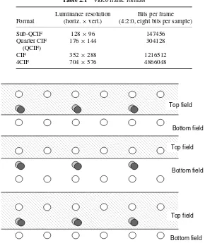
19Table 2.1 Video frame formats
Luminance resolution Bits per frame
Format (horiz.×vert.) (4:2:0, eight bits per sample)
Sub-QCIF 128×96 147456
Quarter CIF 176×144 304128
(QCIF)
CIF 352×288 1216512
4CIF 704×576 4866048
Top field
Bottom field
Top field
Bottom field
Top field
Bottom field
Figure 2.12 Allocaton of 4:2:0 samples to top and bottom fields
Y, Cb and Cr samples to a pair of interlaced fields adopted in MPEG-4 Visual and H.264. It is clear from this figure that the total number of samples in a pair of fields is the same as the number of samples in an equivalent progressive frame.
2.5 VIDEO FORMATS
VIDEO FORMATS AND QUALITY
•
204CIF
CIF QCIF
SQCIF
Figure 2.13 Video frame sampled at range of resolutions
are popular for videoconferencing applications; QCIF or SQCIF are appropriate for mobile multimedia applications where the display resolution and the bitrate are limited. Table 2.1 lists the number of bits required to represent one uncompressed frame in each format (assuming 4:2:0 sampling and 8 bits per luma and chroma sample).
A widely-used format for digitally coding video signals for television production is ITU-R Recommendation BT.601-5 [1] (the term ‘coding’ in the Recommendation title means conversion to digital format and does not imply compression). The luminance component of the video signal is sampled at 13.5 MHz and the chrominance at 6.75 MHz to produce a 4:2:2 Y:Cb:Cr component signal. The parameters of the sampled digital signal depend on the video frame rate (30 Hz for an NTSC signal and 25 Hz for a PAL/SECAM signal) and are shown in Table 2.2. The higher 30 Hz frame rate of NTSC is compensated for by a lower spatial resolution so that the total bit rate is the same in each case (216 Mbps). The actual area shown on the display, theactive area, is smaller than the total because it excludes horizontal and vertical blanking intervals that exist ‘outside’ the edges of the frame.
Each sample has a possible range of 0 to 255. Levels of 0 and 255 are reserved for syn-chronisation and the active luminance signal is restricted to a range of 16 (black) to 235 (white).
2.6 QUALITY
QUALITY
•
21Table 2.2 ITU-R BT.601-5 Parameters
30 Hz frame rate 25 Hz frame rate
Fields per second 60 50
Lines per complete frame 525 625
Luminance samples per line 858 864
Chrominance samples per line 429 432
Bits per sample 8 8
Total bit rate 216 Mbps 216 Mbps
Active lines per frame 480 576
Active samples per line (Y) 720 720
Active samples per line (Cr,Cb) 360 360
a difficult and often imprecise art because there are so many factors that can affect the results. Visual quality is inherentlysubjectiveand is influenced by many factors that make it difficult to obtain a completely accurate measure of quality. For example, a viewer’s opinion of visual quality can depend very much on the task at hand, such as passively watching a DVD movie, actively participating in a videoconference, communicating using sign language or trying to identify a person in a surveillance video scene. Measuring visual quality usingobjective
criteria gives accurate, repeatable results but as yet there are no objective measurement systems that completely reproduce the subjective experience of a human observer watching a video display.
2.6.1 Subjective Quality Measurement
2.6.1.1 Factors Influencing Subjective Quality
Our perception of a visual scene is formed by a complex interaction between the components of the Human Visual System (HVS), the eye and the brain. The perception of visual quality is influenced by spatial fidelity (how clearly parts of the scene can be seen, whether there is any obvious distortion) and temporal fidelity (whether motion appears natural and ‘smooth’). However, a viewer’s opinion of ‘quality’ is also affected by other factors such as the viewing environment, the observer’s state of mind and the extent to which the observer interacts with the visual scene. A user carrying out a specific task that requires concentration on part of a visual scene will have a quite different requirement for ‘good’ quality than a user who is passively watching a movie. For example, it has been shown that a viewer’s opinion of visual quality is measurably higher if the viewing environment is comfortable and non-distracting (regardless of the ‘quality’ of the visual image itself).
VIDEO FORMATS AND QUALITY
•
22A or B
A or B Source video
sequence Display
Video decoder Video
encoder
Figure 2.14 DSCQS testing system
2.6.1.2 ITU-R 500
Several test procedures for subjective quality evaluation are defined in ITU-R Recommenda-tion BT.500-11 [4]. A commonly-used procedure from the standard is the Double Stimulus Continuous Quality Scale (DSCQS) method in which an assessor is presented with a pair of images or short video sequences A and B, one after the other, and is asked to give A and B a ‘quality score’ by marking on a continuous line with five intervals ranging from ‘Excellent’ to ‘Bad’. In a typical test session, the assessor is shown a series of pairs of sequences and is asked to grade each pair. Within each pair of sequences, one is an unimpaired “reference” sequence and the other is the same sequence, modified by a system or process under test. Figure 2.14 shows an experimental set-up appropriate for the testing of a video CODEC in which the original sequence is compared with the same sequence after encoding and decoding. The selection of which sequence is ‘A’ and which is ‘B’ is randomised.
The order of the two sequences, original and “impaired”, is randomised during the test session so that the assessor does not know which is the original and which is the impaired sequence. This helps prevent the assessor from pre-judging the impaired sequence compared with the reference sequence. At the end of the session, the scores are converted to a normalised range and the end result is a score (sometimes described as a ‘mean opinion score’) that indicates therelativequality of the impaired and reference sequences.
Tests such as DSCQS are accepted to be realistic measures of subjective visual quality. However, this type of test suffers from practical problems. The results can vary significantly depending on the assessor and the video sequence under test. This variation is compensated for by repeating the test with several sequences and several assessors. An ‘expert’ assessor (one who is familiar with the nature of video compression distortions or ‘artefacts’) may give a biased score and it is preferable to use ‘nonexpert’ assessors. This means that a large pool of assessors is required because a nonexpert assessor will quickly learn to recognise characteristic artefacts in the video sequences (and so become ‘expert’). These factors make it expensive and time consuming to carry out the DSCQS tests thoroughly.
2.6.2 Objective Quality Measurement
QUALITY
•
23Figure 2.15 PSNR examples: (a) original; (b) 30.6 dB; (c) 28.3 dB
Figure 2.16 Image with blurred background (PSNR=27.7 dB)
processing systems rely heavily on so-called objective (algorithmic) quality measures. The most widely used measure is Peak Signal to Noise Ratio (PSNR) but the limitations of this metric have led to many efforts to develop more sophisticated measures that approximate the response of ‘real’ human observers.
2.6.2.1 PSNR
Peak Signal to Noise Ratio (PSNR) (Equation 2.7) is measured on a logarithmic scale and depends on the mean squared error (MSE) of between an original and an impaired image or video frame, relative to (2n−1)2(the square of the highest-possible signal value in the image, wherenis the number of bits per image sample).
P S N RdB =10 log10
(2n−1)2
M S E (2.7)
VIDEO FORMATS AND QUALITY
•
24The PSNR measure suffers from a number of limitations. PSNR requires an unimpaired original image for comparison but this may not be available in every case and it may not be easy to verify that an ‘original’ image has perfect fidelity. PSNR does not correlate well with subjective video quality measures such as those defined in ITU-R 500. For a given image or image sequence, high PSNR usually indicates high quality and low PSNR usually indicates low quality. However, a particular value of PSNR does not necessarily equate to an ‘absolute’ subjective quality. For example, Figure 2.16 shows a distorted version of the original image from Figure 2.15 in which only the background of the image has been blurred. This image has a PSNR of 27.7 dB relative to the original. Most viewers would rate this image as significantly better than image (c) in Figure 2.15 because the face is clearer, contradicting the PSNR rating. This example shows that PSNR ratings do not necessarily correlate with ‘true’ subjective quality. In this case, a human observer gives a higher importance to the face region and so is particularly sensitive to distortion in this area.
2.6.2.2 Other Objective Quality Metrics
Because of the limitations of crude metrics such as PSNR, there has been a lot of work in recent years to try to develop a more sophisticated objective test that more closely approaches subjective test results. Many different approaches have been proposed [5, 6, 7] but none of these has emerged as a clear alternative to subjective tests. As yet there is no standardised, accurate system for objective (‘automatic’) quality measurement that is suitable for digitally coded video. In recognition of this, the ITU-T Video Quality Experts Group (VQEG) aim to develop standards for objective video quality evaluation [8]. The first step in this process was to test and compare potential models for objective evaluation. In March 2000, VQEG reported on the first round of tests in which ten competing systems were tested under identical conditions. Unfortunately, none of the ten proposals was considered suitable for standardisation and VQEG are completing a second round of evaluations in 2003. Unless there is a significant breakthrough in automatic quality assessment, the problem of accurate objective quality measurement is likely to remain for some time to come.
2.7 CONCLUSIONS
Sampling analogue video produces a digital video signal, which has the advantages of accuracy, quality and compatibility with digital media and transmission but which typically occupies a prohibitively large bitrate. Issues inherent in digital video systems include spatial and temporal resolution, colour representation and the measurement of visual quality. The next chapter introduces the basic concepts of video compression, necessary to accommodate digital video signals on practical storage and transmission media.
2.8 REFERENCES
REFERENCES
•
252. N. Wade and M. Swanston,Visual Perception: An Introduction,2nd edition, Psychology Press,
London, 2001.
3. R. Aldridge, J. Davidoff, D. Hands, M. Ghanbari and D. E. Pearson, Recency effect in the subjective assessment of digitally coded television pictures,Proc. Fifth International Conference on Image Processing and its Applications, Heriot-Watt University, Edinburgh, UK, July 1995.
4. Recommendation ITU-T BT.500-11, Methodology for the subjective assessment of the quality of television pictures, ITU-T, 2002.
5. C. J. van den Branden Lambrecht and O. Verscheure, Perceptual quality measure using a spatio-temporal model of the Human Visual System, Digital Video Compression Algorithms and Technolo-gies,Proc. SPIE,2668, San Jose, 1996.
6. H. Wu, Z. Yu, S. Winkler and T. Chen, Impairment metrics for MC/DPCM/DCT encoded digital video,Proc. PCS01, Seoul, April 2001.
7. K. T. Tan and M. Ghanbari, A multi-metric objective picture quality measurement model for MPEG video,IEEE Trans. Circuits and Systems for Video Technology,10(7), October 2000.
3
Video Coding Concepts
3.1 INTRODUCTION
compress vb.: to squeeze together or compact into less space; condense
compress noun: the act of compression or the condition of being compressed
Compression is the process of compacting data into a smaller number of bits. Video compres-sion (video coding) is the process of compacting or condensing a digital video sequence into a smaller number of bits. ‘Raw’ or uncompressed digital video typically requires a large bitrate (approximately 216 Mbits for 1 second of uncompressed TV-quality video, see Chapter 2) and compression is necessary for practical storage and transmission of digital video.
Compression involves a complementary pair of systems, a compressor (encoder) and a decompressor (decoder). The encoder converts the source data into a compressed form (occupying a reduced number of bits) prior to transmission or storage and the decoder converts the compressed form back into a representation of the original video data. The encoder/decoder pair is often described as aCODEC(enCOder/DECoder) (Figure 3.1).
Data compression is achieved by removingredundancy, i.e. components that are not nec-essary for faithful reproduction of the data. Many types of data containstatisticalredundancy and can be effectively compressed usinglosslesscompression, so that the reconstructed data at the output of the decoder is a perfect copy of the original data. Unfortunately, lossless com-pression of image and video information gives only a moderate amount of comcom-pression. The best that can be achieved with current lossless image compression standards such as JPEG-LS [1] is a compression ratio of around 3–4 times.Lossycompression is necessary to achieve higher compression. In a lossy compression system, the decompressed data is not identical to the source data and much higher compression ratios can be achieved at the expense of a loss of visual quality. Lossy video compression systems are based on the principle of removing
subjectiveredundancy, elements of the image or video sequence that can be removed without significantly affecting the viewer’s perception of visual quality.
H.264 and MPEG-4 Video Compression: Video Coding for Next-generation Multimedia.
VIDEO CODING CONCEPTS
•
28enCOder
video source
transmit
or store DECoder
display
Figure 3.1 Encoder/decoder
temporal correlation
spatial correlation
Figure 3.2 Spatial and temporal correlation in a video sequence
Most video coding methods exploit bothtemporalandspatialredundancy to achieve compression. In the temporal domain, there is usually a high correlation (similarity) between frames of video that were captured at around the same time. Temporally adjacent frames (suc-cessive frames in time order) are often highly correlated, especially if the temporal sampling rate (the frame rate) is high. In the spatial domain, there is usually a high correlation between pixels (samples) that are close to each other, i.e. the values of neighbouring samples are often very similar (Figure 3