Covert Communication in MIMO-OFDM System Using Pseudo
Random Location of Fake Subcarriers
Rizky Pratama Hudhajanto, I Gede Puja Astawa, Amang Sudarsono
Graduate School of Electrical Engineering Politeknik Elektronika Negeri Surabaya(PENS)
Jl. Raya ITS Sukolilo 60111, Indonesia
E-mail: [email protected], {puja,amang}@pens.ac.id
Abstract
Multiple-Input Multiple-Output Orthogonal Frequency Division Multiplexing (MIMO-OFDM) is the most used wireless transmission scheme in the world. However, its security is the interesting problem to discuss if we want to use this scheme to transmit a sensitive data, such as in the military and commercial communication systems. In this paper, we propose a new method to increase the security of MIMO-OFDM system using the change of location of fake subcarrier. The fake subcarriers’ location is generated per packet of data using Pseudo Random sequence generator. The simulation results show that the proposed scheme does not decrease the performance of conventional MIMO-OFDM. The attacker or eavesdropper gets worse Bit Error Rate (BER) than the legal receiver compared to the
Security has always been a part of most discussed data transaction and communication system, however it gained more importance along with the increasing use of wireless communication systems, especially for systems in military and commercial applications. This military and commercial sometime use wireless system as its communication system. However, the main problem is that the wireless signal can be easily received by someone who has the antenna that work in the same frequency with the transmitter which transmits the signal [1]. This leakage can be fatal for communication system which sends very sensitive data.
of parallel flat channel. Also, OFDM can withstand the Inter-Carrier Interference (ICI) phenomenon which is happened in numerous another multicarrier modulation schemes, because of the use of frequency offset. Guard Interval (GI) and Cyclic prefix (CP) are used to combat another wireless channel problem called Inter-Symbol Interferences (ISI). Because of those advantages, OFDM, currently, becomes the widely used wireless transmission modulation and multiplexing method. The applications of OFDM are many and varied which cover Digital Broadcasting, Internet Access, Wireless Network, and Mobile Communications.
Another issue in wireless communication is the presence of obstructions in wireless channel, between transmitter and receiver. These obstructions make reflections of transmitted signal, called multipath effect, which can cause the failure of receiver to receive and demodulate the signal. The solution that has been researched to overcome this effect is by using Multiple-Input Multiple-Output (MIMO) system [3]. By combining this technique with OFDM system, the new system called MIMO-OFDM is. This technique uses the spatial multiple channel for data transmission and receptions, which can increase the BER performance and the speed of data transmission.
Recently, security of OFDM system has been widely researched [4-8]. Most of them are done by implementing cryptographic algorithm in application layer. The development of computer technology, recently, makes the increase of computing capability and may lead to increase of probability that the encrypted data can be decrypted by unauthorized person. Another solution of this leak is by modifying the physical layer of the system. In the physical layer, the transmitted signal is not the real data, but modulated symbols that represent the data and also noise, so that noise can be an additional difficulty for one who wants to attack the system.
time. This system was already proved in simulation that non authorized receiver cannot receive the data. Classen et al [11] conducted a research to compare the covert channel systems proposed by Hijaz and Ma. Classen did the research in practical implementation using Wireless Open-Access Research Platform (WARP). Classen tried to mimic IEEE 802.11 a standard. The practical results showed that the two systems do not influence in BER performance.
In this research we proposed the camouflage subcarrier which is changed over time using pseudorandom generator. We improve the security method proposed by Classen, Hijaz, and Ma by changing the shape of signal over time with the help of pseudorandom generator. We also try to mimic the most common used MIMO-OFDM standard, IEEE 802.11n.
3. ORIGINALITY
In this paper, we propose the new covert communication scheme for MIMO-OFDM system at the physical layer by inserting the fake subcarriers and changing the location of them by using the pseudorandom generator. The MIMO-OFDM system used in this paper mimic the specifications of the WLAN 802.11n. Pseudorandom generator is deployed in transmitter and the receiver side. The detail system of Pseudorandom generator is known by the transmitter and receiver. To start the Pseudorandom Generator as well as the MIMO-OFDM system, the transmitter and receiver have to know the initial start key. This key is already defined inside the transmitter and receiver system and need to be same.
4. SYSTEM DESIGN 5.1 MIMO-OFDM System
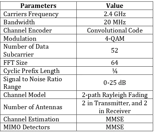
Table 1. MIMO-OFDM Simulation Parameters
Parameters Value
Carriers Frequency 2.4 GHz
Bandwidth 20 MHz
Channel Encoder Convolutional Code
Modulation 4-QAM
Number of Data
Subcarrier 52
FFT Size 64
Cyclic Prefix Length ¼
Signal to Noise Ratio
Range 0-25 dB
Channel Model 2-path Rayleigh Fading
Number of Antennas 2 in Transmitter, and 2 in Receiver
Channel Estimation MMSE
MIMO Detectors MMSE
The subcarrier numbers which are not used in conventional MIMO-OFDM basicly will be inserted with zero padding. This unused subcarrier will be reserved for encryption process which is described later. Pilot symbol is inserted after zero padding insertion process. This pilot symbol is applied to estimate the channel effect. The pilot symbol configuration in this research is High Throughput Long Training Field (HT-LTF). After the symbols are packeted, the packet then will be parallelized and processed with IFFT. The result of this process is referred to as OFDM symbol. The next process is inserting the Cyclic Prefix (CP). After the CP inserting process, OFDM symbol then is serialized and transmitted using antenna.The transmitted signal can be expressed as (1).
Where is the transmitted signal and
is packetized data symbol. The full process of MIMO-OFDM system in transmitter side is showed in Figure 1.
Figure 1. MIMO-OFDM System with 2 Antennas in Transmitter Side
We consider that MIMO-OFDM is applied in the uplink, where the signals from users occupy different channels. In this research, channel model used is Rayleigh Fading Channel Model (RFCM). RFCM is a kind of rational model when a lot of objects in the environment caused transmitted signal scatter before it comes to receiver side. The RFCM model is expressed in mathematical symbol as (2).
Where is the channel response. is
gaussian random real part and is the imaginary part. This channel model consist of real and imaginary part.
In the receiver side, the process starts with receiving transmitted signal from the antenna. The received signal is expressed as (3).
Where is received signal, is transmitted signal, h is channel response, and n is noise vector, with . The next process is Cyclic Prefix (CP) removal. The CP is extracted from the received signal. After that, the signal is ready for FFT process. After FFT process, the pilot symbol is extracted. The extracted pilot symbol then is processed to estimate the channel using MMSE channel estimation method. The channel estimation process can be expressed as (4).
Where is cross-correlation matrix between matrix g and matrix y, , while is auto-correlation matrix from matrix y, . To calculate the estimation value of channel matrix, (5) is used.
F is orthogonal FFT matrix, and the noise variance is expressed as .
After is calculated, the next process is to detect the data using MMSE detection methods. This detector is used to detect the signal and combine the separated signal from two transmitter’s antenna. MMSE eliminate the interference and noise by minimizes the mean square error from the estimated channel matrix, but, the receiver must have the information about Signal to Noise Ratio (SNR). The detector method which is used in this research can be expressed as (7).
Where is detected received signal, is estimated channel matrix, in this research, is equal to , and is undetected received signal.
represents the pseudo-inverse of and is Signal to Noise Ratio (SNR). The last process of MIMO-OFDM’s receiver side is demodulation and decoder. Demodulation is done by QAM demapper. This demodulation process turns the symbol back to bits of information. After that, convolutional decoder is applied. Finally, the bits then will turn back to information message. The full process of MIMO-OFDM receiver is presented in Figure 2.
Figure 2. MIMO-OFDM System with 2 Antennas in Receiver Side
5.2 Pseudo Random Location of Fake Subcarrier
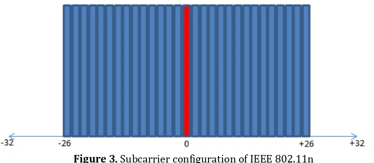
We already analyzed the subcarrier configuration in OFDM standard and found that not all subcarriers in OFDM standard are used. Figure 3 shows the subcarrier configuration of IEEE 802.11n standard.
Figure 3. Subcarrier configuration of IEEE 802.11n
As presented in Figure 3, subcarrier 0 is the center of frequency, and the subcarrier -1 to -26 and +1 to +26 are used for data. Subcarrier -27 to -32 and subcarrier +27 to +32 are not used. Basicly, subcarrier -27 to -32 and +27 to +32 is inserted by zero. This zero insertion in OFDM subcarrier is known as zero padding. Zero padding can reduce complexity of OFDM FFT process, but in this research, we assumed that the security is more important than the data transmission speed.
The basic idea of the proposed method in this research is that the receiver cannot receive if the subcarrier configuration is wrong. From this idea, we make a new configuration of subcarrier for OFDM system, especially for IEEE 802.11n, where this configuration will change automatically over time based on the code generated from pseudorandom generator.
4.2.1 Galois Linear Feedback Shift Register (GLSFR)
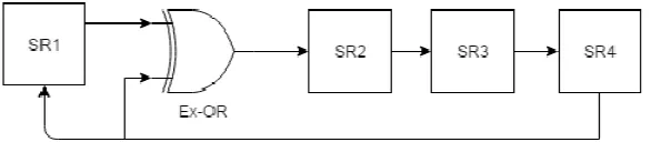
This proposed system starts by generating the code which represents the location of a fake subcarrier. For generating the random code, we use Galois Linear Feedback Shift Register (GLFSR). In choosing the good random sequence generator,we should consider how many periods that the generator can provide. The bigger period is better but we should also consider how many bits that will be used to represent the location of fake subcarrier. The maximal number of bits that can be used is equal to the number of subcarrier. Figure 4 shows the 4-bit GLFSR which is used for the simulation process.
Figure 4. 4-Bit GLFSR Pseudo Random Generator
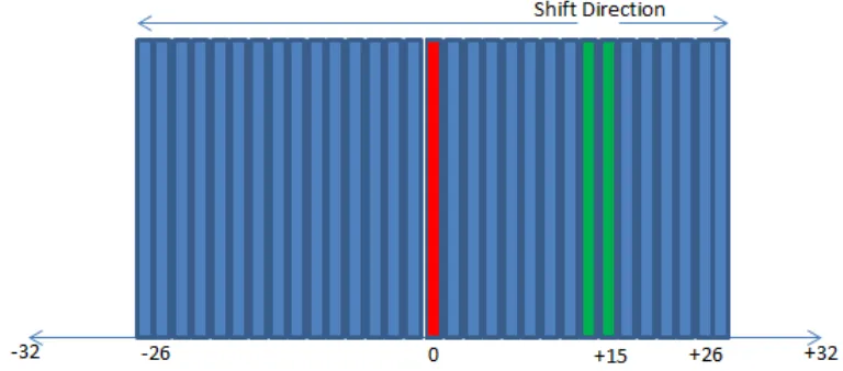
fake subcarriers are shifted left and subcarriers after fake subcarriers are shifted right. Subcarrier 0 is not shifted and kept in its position. Figure 4 shows the subcarrier configuration if the random generator output is 15.
Figure 4. Subcarrier configuration of IEEE 802.11n with camouflage subcarrier
The green subcarriers in Figure 4 are the fake subcarriers. This subcarrier configuration with fake subcarrier inserted is referred to as camouflage subcarrier. All of the positions generated by GLSFR is showed by figure. The initial value of this scheme is 1000.
Table 2. Fake Subcarrier Position Generated by GLSFR
Time First Value Next Value Fake Subcarrier
Position
1 1000 0100 4
2 0100 0010 2
3 0010 0001 1
4 0001 1100 12
5 1100 0110 6
6 0110 0011 3
7 0011 1101 13
8 1101 1010 10
9 1010 0101 5
10 0101 1110 14
11 1110 1111 15
12 1111 1011 11
13 1011 1001 9
14 1001 1000 8
15 1000 0100 4
generator with transmitter side, the receiver can detect the location of first and second fake subcarrier, and then shift back another subcarrier to its real location. Figure 5 shows the MIMO-OFDM transmitter and receiver block diagram with pseudorandom generator, fake subcarrier inserter, and remover.
Figure 5. Transmitter and Receiver Side with Fake Subcarriers (FS) System
5. EXPERIMENT AND ANALYSIS
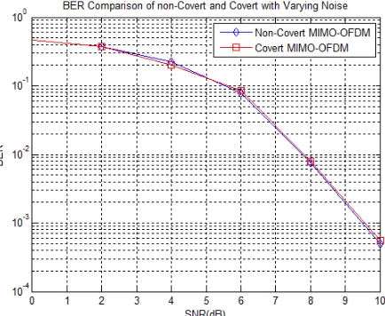
The first question addressing to this system is the BER performance of the system using covert channel and non covert channel. To answer this question, we provide simulation result of BER performance between MIMO-OFDM with proposed covert and conventional non-covert system [13]. The simulation process is done by using the MIMO-OFDM parameters stated in Table 1. Figure 6 shows that the BER performance between covert system and non-covert system are equal.
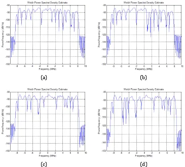
The next simulation is for investigating the shape of MIMO-OFDM signal between covert and non covertsystem. Figure 7 shows that there is only a small difference between them. If this signal is transmitted very fast, the differences between them will be hard to see.
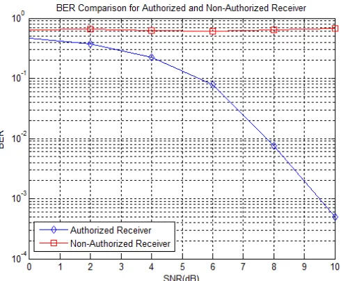
The last simulation is provided to investigate the signal received by authorized receiver and non authorized receiver. We assume that the non-authorized receiver does not know the random shifting scheme in MIMO-OFDM subcarriers and only authorized receiver knows this scheme. We also assume that the transmitter and receiver already know the same initial state to start the GLFS Register to generate the random location of fake subcarrier. Figure 8 shows scenario of the non-authorized receiver try to eavesdrop the communication between the authorized transmitter and authorized receiver. We simulated this scenario, and the result is showed in Figure 9.
Figure 7. The PSD of OFDM Signal for (a) Non-covert system, (b) covert system with fake subcarrier in subcarrier +15, (c) non-covert system with different transmitted
bit, and (d) covert system with fake subcarrier in subcarrier -2
(a) (b)
Figure 8. Scenario Used for Simulation Process
The BER in Figure 9 shows that the unauthorized receiver only gets the BER of around 0.6. It means almost a half of the received signal is not correct. The authorized receiver gets better BER than the unauthorized receiver which means the authorized receiver gets the information. From this result, we prove that the secure communication system is guaranteed.
Figure 9. BER Performance between Authorized Receiver and Non Authorized Receiver
5.1 The Comparative Analysis between Proposed and The Other Schemes
scheme has better performance in channel with a lot of frequency or time mismatch. This is happened because the frame based scheme modifies the frame by inserting something to the packet of data. This insertion and calculation do not affect the modulation schemes, so it will not be affected by rapidly changing amplitude in wireless channel. The disadvantage of frame based scheme is that it is very sensitive to time mismatch, because it does a calculations in received packet data and sometimes can cause a delay. The symbol based scheme has better performance in channel with frequency or time mismatch because this scheme only modifies the modulation process and does not modify the packet of data. The covert scheme proposed by Hijaz is frame based, while the scheme proposed by Ma is symbol based.
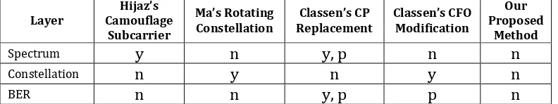
We also investigate the detection probability between proposed sceme and other schemes. Table summarizes the detectability of all covert schemes in OFDM system. The camouflage subcarrier proposed by Hijaz can be detected if the unauthorized receiver take a look at the spectrum by using spectrum analyzer. The constellation rotation proposed by Ma cannot be detected at the spectrum but can be easily detected by looking at IQ constellation diagram. Classen’s CP replacement method uses modified CP to cover the transmission. This will reduce the performance of OFDM system because CP is essential in detecting the packet start and stop. Classen’s Carrier Frequency Offset (CFO) modification also has the similar problem with CP replacement. Both of them modify the essential synchronization system of OFDM. However, all of the covert channel scheme can be detected by looking at IQ constellation. Furthermore, the data can be extracted if the signal is succesfully decoded and checked. Our proposed scheme has a pseudorandom location of fake subcarrier. It means it will be hard to decode because the location of fake subcarrier is always moving.
signal, which means that the OFDM performance will not be decreased if the covert system is applied. In the future work, we will try to implement this method in real device using Universal Software Radio Peripheral (USRP). We will analyze this method in real condition with real wireless channel environment.
Acknowledgements
This research is granted by PoliteknikElektronikaNegeri Surabaya (PENS) Freshgraduate Scholarship for Master’s Degree Students.
REFERENCES
[1] Y. Liang H., V. Poor, S.Shamai, Secure Communication over Fading Channel,IEEE Transactions of Information Theory, Vol.54, No. 6, pp. 2470-2492, 2008.
[2] Z. Wang, X. Ma,G. B. Giannakis, OFDM or Single Carrier Block Transmission?,IEEE Transactions on Communications, Vol.52, No. 3, pp. 380-394, 2004.
[3] G.L. Suber, J. R. Barry, S. W. Mclaughlin, and Ye Li, Broadband MIMO-OFDM Wireless Communications, Proceedings of the IEEE, Vol. 92, No. 2, pp. 271-294, 2004. Proceedings of SPIE Electronic Imaging,San Jose, pp. 68-70, 2008.
[7] X. Tan, K. Borle, W. Du, B. Chen, Cryptography Link Signature for Spectrum Usage Authentication in Cognitive Radio, In Proceedings of The Fourth ACM Conference of Wireless Network Security, San Jose, pp. 79-90, 2011.
[8] M. Willhelm, I. Martinovic, J. B. Schmitt, V. Lenders, WiFire: a Firewall for the Wireless Network, In Proceeding of the ACM 2011 SIGCOMM, Toronto, pp. 456-457, 2011.
[9] Z. Hijaz, V. Frost, Exploiting OFDM Systems for Covert Communication, In Military Communications Conference, pp. 2149-2155, 2010.
[10] R. Ma, L. Dai, Z. Wang, Secure Communication in TDS-OFDM Using Constellation Rotation and Noise Insertion, IEEE Transactions on Consumer Electronics, Vol. 56, No. 3, pp. 1328-1332, 2010.
[12] The Institute of Electrical and Electronic Engineers, Inc.,IEEE Standard of Information Technology,IEEE Press (New York), 802.11-2012, 2012. [13] R. Raissawinda, I. G. P. Astawa, Y. Moegiharto, A. Zainudin, I. D.