DFIG Control Scheme of Wind Power Using ANFIS Method in Electrical
Power Grid System
Ramadoni Syahputra and Indah Soesanti
Department of Electrical Engineering, Faculty of Engineering UniversitasMuhammadiyah Yogyakarta, Indonesia
Abstract
This paper presents the control scheme of doubly-fed induction generator (DFIG) using ANFIS method. The scheme is a part of wind power in order to on-grid to electrical power grid system. In this work, wind turbine driven is by DFIG which feeds ac power to distribution network. The system is modeled and simulated in the Simulink-Matlab software in such a way that it can be suited for modeling of induction generator configurations. The system model makes use of rotor reference frame using dynamic vector control approach for machine reference model. ANFIS controller is applied to rotor side converter for controlling active power and regulating voltage of wind power. In order to studying the performance of theANFIS controller, the different abnormal conditions are examined even the worst case. Simulation results prove the good performance of ANFIS control unit as improving power quality and stability of wind power system. Keywords: DFIG, Control Scheme, Wind Power, ANFIS, Grid System.
Introduction
Wind power system is the fastest growing and most promising renewable energy resources among them due to both technically and economically viable [1]-[3]. Many applications of wind power can be found in a wide power range from a few kilowatts to several megawatts [4]-[5]. The wind power can be found in small scale off-grid standalone systems or large scale grid-connected wind farms. Due to lack of control on active and reactive power, this type of distributed generation causes problems in the interconnection system. Therefore, this scheme requires accurate modeling, control and selection of appropriate wind power system. During last two decades, the high penetration of wind powers has been closely related to the advancement of the wind turbine technology and the way of how to control [6]. Doubly fed induction generator (DFIG) is one of the most popular wind turbines which includes an induction generator with slip ring, a partial scale power electronic converter and a common DC-link capacitor [7]-[9]. Doubly-fed induction generators are receiving increasing attention for wind energy conversion system during such situation. Because the main advantage of such generators is that, if the rotor current is governed applying field orientation control-carried out using commercial double sided PWM inverters, decoupled control of stator side active and reactive power results and the power processed by the power converter is only a small fraction of the total system power. So, doubly-fed induction generator
with vector control is very attractive to the high performance variable speed drive and generating applications [10]-[11]. With increasing penetration of wind-derived power in interconnected power systems, it has become necessary to model the complete wind energy systems in order to study their impact and also to study wind power plant control. Along with the development of wind energy system, power electronic converter technologies also develop significantly. The technology which encompasses a back to back AC-DC-AC voltage source converter has two main parts; grid side converter (GSC) that rectifies grid voltage and rotor side converter (RSC) which feeds rotor circuit. Power converter only processes slip power therefore it’s designed in partial scale and just about 30% of generator rated power which makes it attractive from economical point of view [12]-[14]. Many different structure and control algorithm can be used for control of power converter. One of the most common control techniques is decouple PI control of output active and reactive power to improve dynamic behavior of wind turbine. But due to uncertainty about the exact model and behavior of some parameters such as wind, wind turbine, etc., and also parameters values differences during operation because of temperature, events or unpredictable wind speed, tuning of PI parameters is one of the main problems in this control method. The use of artificial intelligence (AI) technique in many field have been very popular among researchers [15]-[23]. Therefore, this study investigates dynamic modeling of avariable speed DFIG wind power using ANFIScontroller in Simulink Matlabsoftware. ANFIS is one of the AI methods used to control a system [24]-[31]. Differentparameters in normal and abnormal conditions based on adaptive neuro-fuzzy control are investigated. A main grid with a 9MW DFIG wind turbine is used and focuses turned to fuzzy control unit and itseffects on the power quality and system response. Wind Power in Grid System
(1) whereCp is the Power Co-efficient, ρ is the air density in
kg/m3, A is the area of the turbine blades in m2and V is the wind velocity in m/sec.The power coefficient Cpgives the fraction of the kinetic energy that is converted into mechanical energy by the wind turbine. It is a function of the tip speed ratio λ and depends on the blade pitch angle for pitch-controlled turbines. The tip speed ratio may be defined as the ratio of turbine blade linear speed and the wind speed
(2)
Substituting (2) in (1), we have:
(3) The output torque of the wind turbine Tturbineis calculated by the following equation (4):
(4) whereR is the radius of the wind turbine rotor (m) There is a value of the tip speed ratio at which the power coefficient is maximum. Variable speed turbines can be made to capture this maximum energy in the wind by operating them at a blade speed that gives the optimum tip speed ratio. This may be done by changing the speed of the turbine in proportion to the change in wind speed. Figure 1 shows how variable speed operation will allow a wind turbine to capture more energy from the wind [8]. As one can see, the maximum power follows a cubic relationship. For variable speed generation, an induction generator is considered attractive due to its flexible rotor speed characteristic in contrast to the constant speed characteristic of synchronous generator.
Figure 1: Wind turbine characteristics [8]
In this study, the rotor is running at sub-synchronous speed for wind speeds lower than 10 m/s and it is running at a super-synchronous speed for higher wind speeds. The turbine mechanical power as function of turbine speed is displayed in for wind speeds ranging from 5 m/s to 16.2 m/s.
Induction machines are used extensively in the power system as induction motors but are not widely used as generators [8]. Despite their simplicity in construction, they are not preferred as much as synchronous generators. This is mainly due to the defined relationship between the export of P and absorption of Q. However, induction generators have the benefits of providing large damping torque in the prime mover, which makes it suitable for the application in fixed speed wind turbines. The fixed speed wind turbine uses a squirrel cage induction generator that is coupled to the power system through a connecting transformer. Due to different operating speeds of the wind turbine rotor and generator, a gearbox is used to match these speeds. The generator slip slightly varies with the amount of generated power and is therefore not entirely constant.
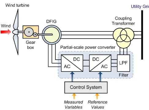
General concept of the doubly-fed induction generator is shown in Figure 2. The mechanical power generated by the wind turbine is transformed into electrical power by an induction generator and is fed into the main grid through the stator and the rotor windings. The rotor winding is connected to the main grid by self-commutated AC/DC converters allowing controlling the slip ring voltage of the induction machine in magnitude and phase angle.In contrast to a conventional, singly-fed induction generator, the electrical power of a doubly-fed induction machine is independent from the speed. Therefore, it is possible to realize a variable speed wind generator allowing adjusting the mechanical speed to the wind speed and hence operating the turbine at the aerodynamically optimal point for a certain wind speed range.
Figure 2: Typical of doubly-fed induction generator
past, the AC-ACconverter connected to the rotor consisted of arectifier and inverter based on thyristor bridges.Nowadays, AC-AC converters are equipped with bidirectionalIGBT's, connecting the rotor of thevariable speed doubly fed induction generator to theelectrical grid.
ANFIS Method
Algorithm of adaptive neuro-fuzzy inference system (ANFIS) has been became a popular method in control area. In this section, we give a brief description of the principles of ANFIS which are referred to [23]. The basic structure of the type of fuzzy inference system could be seen as a model that maps input characteristics to input membership functions. Then it maps input membership function to rules and rules to a set of output characteristics. Finally it maps output characteristics to output membership functions, and the output membership function to a singlevalued output or a decision associated with the output. It has been considered only fixed membership functions that were chosen arbitrarily.
The neuro-adaptive learning method works similarly to that of neural networks. Neuro-adaptive learning techniques provide a method for the fuzzy modeling procedure to learn information about a data set. It computes the membership function parameters that best allow the associated fuzzy inference system to track the given input/output data. A network-type structure similar to that of a neural network can be used to interpret the input/output map so it maps inputs through input membership functions and associated parameters, and then through output membership functions and associated parameters to outputs,. The parameters associated with the membership functions changes through the learning process. The computation of these parameters is facilitated by a gradient vector. This gradient vector provides a measure of how well the fuzzy inference system is modeling the input/output data for a given set of parameters. When the gradient vector is obtained, any of several optimization routines can be applied in order to adjust the parameters to reduce some error measure (performance index). This error measure is usually defined by the sum of the squared difference between actual and desired outputs. ANFIS uses a combination of least squares estimation and back propagation for membership function parameter estimation.
The suggested ANFIS has several properties:
1. The output is zeroth order Sugeno-type system. 2. It has a single output, obtained using weighted
average defuzzification. All output membership functions are constant.
3. It has no rule sharing. Different rules do not share the same output membership function, namely the number of output membership functions must be equal to the number of rules.
4. It has unity weight for each rule.
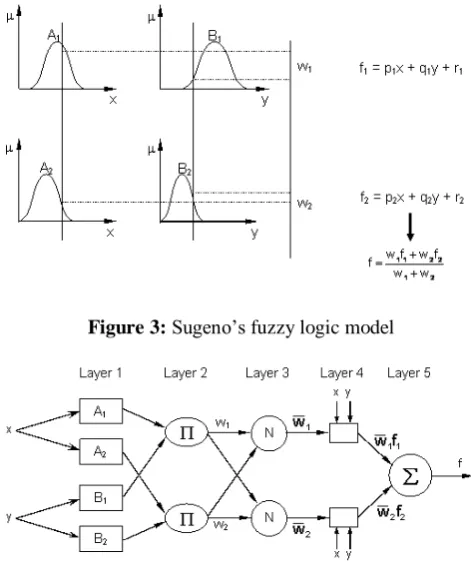
Figure 3 shows Sugeno’s fuzzy logic model, while Figure 4 shows the architecture of the ANFIS, comprising by input, fuzzification, inference and defuzzification layers. The network can be visualized as consisting of inputs, with N neurons in the input layer and F input membership functions for each input, with F*N neurons in the fuzzification layer. There are FN rules with FN neurons in the inference and
defuzzification layers and one neuron in the output layer. For simplicity, it is assumed that the fuzzy inference system under consideration has two inputs x and y and one output z as shown in Figure 2. For a zero-order Sugeno fuzzy model, a common rule set with two fuzzy if-then rules is the following: Rule 1: If x is A1 and y is B1, Then f1 = r1 (5)
Rule 2: If x is A2 and y is B2, Then f2 = r2 (6)
Figure 3: Sugeno’s fuzzy logic model
Figure 4: The architecture of the ANFIS with two inputs and one output. (small,large, etc.) associated with this node function. In other words,
O
1iis the membership function of Ai and it specifiesLayer 2: Every node in this layer is a circle node labeled Π fact, other T-norm operators that performs generalized AND can be used as the node function in this layer.)
Layer 3: Every node in this layer is a circle node labeled N. The i-th node calculates the ratio of the i-th rule’s firing strength to the sum of all rules firing strengths:
2
Layer 5: The single node in this layer is a circle node labeled Σ that computes the overall output as the summation of all method to control the doubly-fed induction generator in wind energy conversion system, the overall system is simulated using Matlab Simulink software.The example described in this section illustrates the steady-state and dynamic performance of a 9 MW wind farm connected to a distribution system.The wind farm consists of six 1.5 MW wind turbines connected to a 25 kV distribution system exporting power to a 120 kV grid through a 30 km 25 kV feeder. A 2300V, 2 MVA plant consisting of a motor load (1.68 MW induction motor at 0.93 PF) and of a 200 kW resistive load is connected on the same feeder at bus B25. A 500 kW load is also connected on the 575 V bus of the wind farm. The diagram of this system in Matlab Simulink model is illustrated in Figure 5.
Wind turbines use a doubly-fed induction generator consisting of a wound rotor induction generator and an AC/DC/AC IGBT-based PWM converter. The stator winding is connected directly to the 60 Hz grid while the rotor is fed at variable frequency through the AC/DC/AC converter. The doubly-fed induction generator technology allows extracting maximum energy from the wind for low wind speeds by optimizing the turbine speed, while minimizing mechanical stresses on the turbine during gusts of wind. The optimum turbine speed producing maximum mechanical energy for a given wind speed is proportional to the wind speed. Another advantage of the doubly-fed induction machine technology is the ability for power electronic converters to generate or Turbine Data Menu
and the Turbine Power Characteristics absorb reactive power, thus eliminating the need for installing capacitor banks as in the case of squirrel-cage induction generators. The terminal voltage will be controlled to a value imposed by the reference voltage (Vref= 1 pu) and the voltage droop (Xs= 0.02 pu).
Figure 5: Wind energy connected to a distribution system.
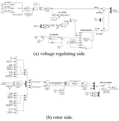
(a) voltage regulating side.
(b) rotor side.
Figure 6: DFIG control scheme using ANFIS method
Figure 6 shows DFIG control scheme using ANFIS method. The figure describes the block diagram of rotor side converter to which adaptive neuro-fuzzy (ANFIS) controller is applied. The main objectives of this part are active power control and voltage regulation of DFIG wind turbine using output reactive power control. As illustrated in Figure 6 rotor side converter manages to follow reference active (Pref) power and voltage (Vref) separately using fuzzy controllers, hysteresis current controller converter and vector control algorithm. Inputs of fuzzy controller are error in active and reactive power or voltage and the rate of changes in errors in any time interval. After the production of reference d-and q-axis rotor currents, they converted to a-b-c reference frame using flux angle, rotor angle and finally slip angle calculation and Concordia and Park transformation matrix. Then they applied to a hysteresis current controller to be compared with actual currents and produce switching time intervals of converter.
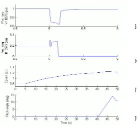
(0.15 s) phase-to-ground fault is applied on phase A at B25 bus. When the wind turbine is in Voltage regulation mode, the positive sequence voltage at wind turbine terminals (V1_B575) drops to 0.8 pu during the fault, which is above the undervoltage protection threshold (0.75 pu for a t>0.1 s). The wind farm therefore stays in service, as shown in Figure 7. However, if the Var regulation mode is used with Qref=0, the voltage drops under 0.7 pu and the undervoltage protection trips the wind farm. We can now observe that the turbine speed increases. At t=40 s the pitch angle starts to increase to limit the speed, as shown in Figure 8.
Figure 7: Waveforms of DFIG wind energy during fault at Bus B25 (Voltage Regulation Mode).
Figure 8: Waveforms of DFIG wind energy during fault at Bus B25 (Var Regulation Mode).
Conclusions
This paper has described the control scheme of doubly-fed induction generator (DFIG) wind energy conversion system using ANFIS approach. The wind turbine driven by doubly-fed induction generator is a part of distributed generation which feeds ac power to the distribution network. The system is modeled and simulated in the Simulink Matlabsoftware in such a way that it can be suited for modeling of all types of induction generator configurations. The model makes use of rotor reference frame using dynamic vector approach for machine model. All power system components and the adaptive neuro-fuzzy controller are simulated in Matlab Simulink software. For studying the performance of controller, different abnormal conditions are applied even the worst case. Simulation results prove the excellent performance of ANFIS control unit as improving power quality and stability of wind turbine.
References
[1] R. Syahputra, (2012), “Distributed Generation: State of the Arts dalamPenyediaanEnergiListrik”, LP3M UMY, Yogyakarta, 2012.
[2] R. Syahputra, (2013), “A Neuro-Fuzzy Approach For the Fault Location Estimation of Unsynchronized Two-Terminal Transmission Lines”, International Journal of Computer Science & Information Technology (IJCSIT), Vol. 5, No. 1, pp. 23-37. [3] A. Jamal, R. Syahputra, (2011), “Model Power
System Stabilizer Berbasis Neuro-Fuzzy Adaptif”,
SemestaTeknika, Vol. 14, No. 2, 139-149, 2011, pp. 139-149.
[4] R. Syahputra, (2012), “Fuzzy Multi-Objective Approach for the Improvement of Distribution Network Efficiency by Considering DG”,
International Journal of Computer Science & Information Technology (IJCSIT), Vol. 4, No. 2, pp. 57-68.
[5] R. Syahputra, I. Robandi, M. Ashari, (2012), “Reconfiguration of Distribution Network with DG Using Fuzzy Multi-objective Method”, International Conference on Innovation, Management and Technology Research (ICIMTR), May 21-22, 2012, Melacca, Malaysia.
[6] R. Syahputra, I. Robandi, M. Ashari, (2014), “Distribution Network Efficiency Improvement Based on Fuzzy Multi-objective Method”. IPTEK
Journal of Proceedings Series. 2014; 1(1): pp. 224-229.
[7] R. Syahputra, M. Ashari, I. Robandi, (2011), “Modeling and Simulation of Wind Energy Conversion System in Distributed Generation Units”.
International Seminar on Applied Technology, Science and Arts (APTECS). 2011; pp. 290-296. [8] R. Syahputra, I. Robandi, M. Ashari, (2011),
Technology, Science and Arts (APTECS). 2011; pp. 493-501.
[9] Jamal, A.,Suripto, S., Syahputra, R. (2015). Multi-Band Power System Stabilizer Model for Power Flow Optimization in Order to Improve Power System Stability.Journal of Theoretical and Applied
Information Technology, 80(1), pp. 116-123.
[10] Syahputra, R., Robandi, I., Ashari, M. (2014). Optimization of Distribution Network Configuration with Integration of Distributed Energy Resources Using Extended Fuzzy Multi-objective Method.International Review of Electrical
Engineering, 9(3), pp. 629-639.
[11] Syahputra, R., Robandi, I., Ashari, M. (2014). “Optimal Distribution Network Reconfiguration with Penetration of Distributed Energy Resources”,
Proceeding of 20141stInternational Conference on
Information Technology, Computer, and Electrical Engineering, ICITACEE 2014, pp. 388-393.
[12] Syahputra, R., Robandi, I., Ashari, M. (2014). Performance Analysis of Wind Turbine as a Distributed Generation Unit in Distribution System.International Journal of Computer Science &
Information Technology (IJCSIT), Vol. 6, No. 3, pp. 39-56.
[13] Syahputra, R., Robandi, I., Ashari, M. (2015). Performance Improvement of Radial Distribution Network with Distributed Generation Integration Using Extended Particle Swarm Optimization Algorithm.International Review of Electrical
Engineering, 10(2). pp.293-304.
[14] Syahputra, R., Robandi, I., Ashari, M. (2015). Reconfiguration of Distribution Network with DER Integration Using PSO Algorithm.TELKOMNIKA, 13(3). pp.759-766.
[15] Rohmah, R.N., Susanto, A., Soesanti, I. (2013). Lung tuberculosis identification based on statistical feature of thoracic X-ray. 2013 International Conference on
Quality in Research, QiR 2013-In Conjunction with ICCS 2013: The 2nd International Conference on Civic Space, pp. 19-26.
[16] Syahputra, R. (2010). Fault Distance Estimation of Two-Terminal Transmission Lines.Proceedings of
International Seminar on Applied Technology, Science, and Arts (2nd APTECS), Surabaya, 21-22 Dec. 2010, pp. 419-423.
[17] Soedibyo, Ashari, M., Syahputra, R. (2014), Power loss reduction strategy of distribution network with distributed generator integration. 1stInternational
Conference on Information Technology, Computer, and Electrical Engineering, ICITACEE 2014, pp. 404-408.
[18] Jamal, A.,Syahputra, R. (2013). UPFC Based on Adaptive Neuro-Fuzzy for Power Flow Control of Multimachine Power Systems.International Journal
of Engineering Science Invention, 2(10), pp. 05-14. [19] Jamal, A., Syahputra, R. (2014). Power Flow Control
of Power Systems Using UPFC Based on Adaptive Neuro Fuzzy. IPTEK Journal of Proceedings Series. 2014; 1(1): pp. 218-223.
[20] Syahputra, R., Robandi, I., Ashari, M. (2015). PSO Based Multi-objective Optimization for Reconfiguration of Radial Distribution Network.International Journal of Applied
Engineering Research,10(6), pp. 14573-14586.
[21] Syahputra, R. (2015).
SimulasiPengendalianTemperaturPada Heat Exchanger MenggunakanTeknik Neuro-Fuzzy Adaptif.JurnalTeknologi, 8(2), pp. 161-168.
[22] Soesanti, I.,Syahputra, R. (2016). Batik Production Process Optimization Using Particle Swarm OptimizationMethod.Journal of Theoretical and
Applied Information Technology, 86(2), pp. 272-278. [23] Syahputra, R., Soesanti, I., Ashari, M. (2016).
Performance Enhancement of Distribution Network with DG Integration Using Modified PSO Algorithm.
Journal of Electrical Systems, 12(1), pp. 1-19. [24] Soesanti, I. (2016). Web-Based Monitoring System
on the Production Process of Yogyakarta Batik Industry, Journal of Theoretical and Applied
Information Technology, 87(1), pp. 146-152.
[25] Syahputra, R., Soesanti, I. (2016). Design of Automatic Electric Batik Stove for Batik Industry.Journal of Theoretical and Applied
Information Technology, 87(1), pp. 167-175.
[26] Afrisal, H., Faris, M., Utomo P., G.,Grezelda, L., Soesanti, I., Andri F., M. (2013). Portable smart sorting and grading machine for fruits using computer vision. Proceeding of 2013 International
Conference on Computer, Control, Informatics and Its Applications (IC3INA) 2013, pp. 71-75.
[27] Rahadian, H., Sutopo, B., Soesanti, I. (2015). TGS2611 performance as biogas monitoring instrument in digester model application.
Proceeding-2015 International Seminar on Intelligent Technology and Its Applications, ISITIA 2015, pp. 119-124.
[28] Nugroho, H.A., Faisal, N., Soesanti, I., Choridah, L. (2014). Analysis of digital mammograms for detection of breast cancer. Proceeding-2014
International Conference on Computer, Control, Informatics and Its Applications: "New Challenges and Opportunities in Big Data", IC3INA 2014, pp. 25-29.
[29] Rohmah, R.N., Susanto, A., Soesanti, I., Tjokronagoro, M. (2013). Computer Aided Diagnosis for lung tuberculosis identification based on thoracic X-ray. Proceedings-2013 International
Conference on Information Technology and Electrical Engineering: "Intelligent and Green Technologies for Sustainable Development", ICITEE 2013, pp.73-78.
[30] Ratnasari, N.R., Susanto, A., Soesanti, I., Maesadji. (2013). Thoracic X-ray features extraction using thresholding-based ROI template and PCA-based features selection for lung TB classification purposes. Proc. of 2013 3rd Int. Conf. on
Technol. for Improvement of Health, Safety, and Environ., ICICI-BME 2013, pp.65-69.
[31] Nugroho, H.A.,Faisal, N.,Soesanti, I.,Choridah, L. (2014). Identification of malignant masses on digital mammogram images based on texture feature and correlation based feature selection.