i E M E R U S A E M & S I S Y L A N
A NTOFSERVICECONTINUITY G N I S U Y B T N E M E C N A H N
E AUTOMATICPROTECTIONSYSTEM( APS)I N C I N U M M O C C I T P O R E B I
F ATIONLINK
ii A K A L E M A I S Y A L A M L A K I N K E T I T S R E V I N U R E T U P M O K N A A R E T U R U J E K N A D K I N O R T K E L E N A A R E T U R U J E K I T L U K A F N A R O P A L S U T A T S N A H A S E G N E P G N A R O B I I A D U M A N A J R A S K E J O R P k e j o r P k u j a T : E M E R U S A E M & S I S Y L A N
A NTOFSERVICECONTINUITY
G N I S U Y B T N E M E C N A H N
E AUTOMATIC PROTECTION
E B I F N I ) S P A ( M E T S Y
S ROPTICCOMMUNICATIONLINK i s e S n a ij a g n e
P : 1 0 / 1 1
a y a
S MOHDHAFIZBINMOHDNORDIN
n a g n e d n a a k a t s u p r e P i d n a p m i s i d i n i a d u M a n a jr a S k e j o r P n a r o p a L n a k r a n e b m e m u k a g n e
m syarat
-:t u k ir e b i tr e p e s n a a n u g e k t a r a y s .
1 LaporanadalahhakmiilkUniversti iTeknika lMalaysiaMelaka. .
2 Perpustakaandibenarkanmembuats ailnanuntukt ujuanpengaijans ahaja. .
3 Perpustakaandibenarkanmembuats ailnanl aporani nis ebaga ibahanpetrukaranantarainsttius i .i g g n it n a ij a g n e p .
4 Sliat andakan( √ : )
* T I L U
S k*(eMpeennitgnagnadnunMga ilmayaskilaus mepae tytra inyganbgert deramjraahktkuebsdela idmaalatamnAatKauTA ) 2 7 9 1 I M S A R A I S H A R * * D A H R E
T **(Mengandung imaklumatt erhadyangt elahdtientukanoleh
) n a k n a l a ji d n a k i d il e y n e p a n a m i d n a d a b /i s a s i n a g r o D A H R E T K A D I T : h e l o n a k h a s i D _ _ _ _ _ _ _ _ _ _ _ _ _ _ _ _ _ _ _ _ _ _ _ _ _ _ ___________________________________ ) S I L U N E P N A G N A T A D N A T
( (COPDANTANDATANGANPENYELIA)
ii i
n i d e ti c s a s e t o u q r o f t p e c x e t r o f f e n w o y m f o t l u s e r s i tr o p e r s i h t t a h t e r a l c e d y b e r e h I “
” .s e c n e r e f e r e h t
e r u t a n g i
S :………. e
m a
N :MOHDHAFIZBINMOHDNORDIN e
t a
v i
n i t n e i c if f u s s i tr o p e r s i h t n o i n i p o y m n i d n a t r o p e r s i h t d a e r e v a h I t a h t e r a l c e d y b e r e h I “
g n ir e e n i g n E c i n o rt c e l E f o r o l e h c a B f o d r a w a e h t r o f y ti l a u q d n a e p o c s e h t f o s m r e t
” .) c i n o rt c e l E n o it a c i n u m m o c e l e T (
e r u t a n g i
S :………. e
m a N s ’ r o s i v r e p u
S :MR .CHAIRULSYAHBINABDULWASLI e
t a
v N O I T A C I D E D d e t a c i d e d s i t c e j o r p s i h T ,t n e r a p t s e r a e d y m o t d n a f o s u Y d h o M n i b n i d r o N d h o
M Rosmawat ibint iSamsuddin, ,s d n e ir f y m o t t e g r o f t o n d n a , s g n il b i s y m l l a y m r o f y a r p y l e r e c n i s s y a w l a e v a h o h w . y r o l g d n a s s e c c u s y m o
T Supervisor, il s a W l u d b A n i b h a y s l u ri a h C . r M t h g u a t d n a g n i v o l r u o y r o f u o y k n a h
T os
t a h
i v T N E M E G D E L W O N K C A s i tI . l u fi c r e M t s o M e h T d n a l a i c if e n e B t s o M e h T , T . W . S h a ll A f o e m a n e h t n I l A e h t f o e d u ti t a r g e v r e s t s e p e e d h ti
w -Mighty tha tgive sme srtength and ab litiy to .t r o p e r t c e j o r p r a e y l a n if s i h t e t e l p m o c o t s k n a h t l a i c e p s y m s s e r p x e o t y ti n u tr o p p o s i h t e k a t o t e k il d l u o w I , ll a f o t s ri F , e s i v d a , e c n a t s i s s a , e c n a d i u g e h t r o f i l s a W l u d b A n i b h a y s l u ri a h C r M , r o s i v r e p u s y m d n a t n e m p o l e v e d e h t h g u o r h t y a w e h t ll a e m e d i u g o t l u f p l e h g n i e b o s l a d n a s s e n d n i k g o r
p res so fmy ifna lyea rproject .Above al land the mos tneeded ,h e provided me .s y a w s u o ir a v n i tr o p p u s d n a t n e m e g a r u o c n e g n i h c n il f n u l a i c u r c d n a , n o i s i v r e p u s , e c i v d a r i e h t r o f s d n e ir f y m o t s e o g o s l a n o it a i c e r p p a y M o b k c a b a m e h t e d a m h c i h w , n o it u b ir t n o
c ne o fthi sprojec tto become successfully . . t c e j o r p e h t f o s s e r g o r p g n ir u d s d n a h g n i d n e l r o f u o y k n a h T d e v o l e b y m o t s k n a h t l a n o it p e c x e y m s s e r p x e o t e k il d l u o w o s l a I , y ll a n i F ri d n i r o y lt c e ri d e m s p l e h d n a s r e y a r p g n i d n e n u d n a t r o p p u s r i e h t r o f s t n e r a
p eclty in
ii v T C A R T S B A t u o b a s i t c e j o r p s i h
T Analysi s & Measuremen t o f Service Conitnutiy b t n e m e c n a h n
E y Using Automaitc Proteciton System (APS ) in Fibe r Opitc k n i L n o it a c i n u m m o
C .TheAPSsystemi si mpo trantt oprovideprotecitonf o r ifbe ropitc e d i v o r p l li w m e t s y s s i h T . s y a d a w o n y l e d i w d e s u n e e b e v a h t a h t k n il n o it a c i n u m m o c e h t f o t n e m e l e n i a m e h T . m e t s y s y r e v o c e r t l u a f t s a f e d i v o r p d n a k n il e h t r o f n o it c e t o r p o it c e t o r p s i m e t s y
s n ifbe rand op itca lswtiches .Thi sprojec twli lanalyze the system , e m it g n i h c ti w s , s s o l n o it r e s n i s a h c u s h c ti w s l a c it p o e h t f o s r e t e m a r a p e m o s n o d e s a b t s e b e h t ,s r e t e m a r a p l l a g n i z y l a n a y B . h c ti w s e h t f o s r e t e m a r a p r e h t o d n a e g a tl o v g n i v ir d t a h t h c ti w
ii i v
K A R T S B A
k e j o r
P ii n adalah tentang Anailsis & Pengukuran Peningkatan Perkhidmatan n
a k a n u g g n e
M Sistem Perilndungan Automaitk (APS )d i tailan komunikas igenitan k
it p
o .SistemA PS adalah penitnguntukmember iperilndunganuntuk tailankomunikasi n
a it n e
g opitk yang telah digunakan secara meluas keitka ii .n Sistem ii n akan n
a k ir e b m e
m perilndungan untuk tailan nd a menyediakan sistem pemuilhan yang cepat . n
e m e l
E utama d a ir sistem ini adalah genitan opitk dan sui sopitk .Projek ii n akan a
s il a n a g n e
m sistem berdasarkan beberapa parameter d a ir s uis opitk seperit kada r a
s a u k n a g n a li h e
k ,masapenukaranan, votlandan l ain- nlai .Denganmenganailsissemua r
e t e m a r a
p ,s uis terbaik dapa tdiplih untuk digunakan d idalam Sistem Perilndungan k
it a m o t u
x i
S T N E T N O C F O E L B A T
CHAPTER TITLE PAGE
E L T I T T C E J O R
P i
M R O F N O I T A M R I F N O C T R O P E R S U T A T
S ii
T E E H S L A V O R P P
A i ii
T E E H S N O I T A R A L C E
D i v
N O I T A C I D E
D v
T N E M E G D E L W O N K C
A v i
T C A R T S B
A v ii
K A R T S B
A v iii
S T N E T N O C F O E L B A
T i x
F O T S I
L TABLES x ii
S E R U G I F F O T S I
L x iii
S E C I D N E P P A F O T S I
L xv
I INTRODUCTION 1
1 .
1 BACKGROUND 1
2 .
1 PROBLEMSTATEMENT 3 3
.
1 OBJECTIVES 3
4 .
1 SCOPEOFWORKS 4
5 .
1 ORGANIZATIONOFTHEREPORT 5
I
x
1 .
2 INTRODUCTION 6
2 .
2 INTRODUCTIONTOFIBEROPTIC 6 3
.
2 FIBEROPTICELEMENTINCOMMUNICATION M
E T S Y S
8
4 .
2 LOSSI NOPTICALCOMMUNICATIONSYSTEM 11 5
.
2 FIBEROPTICLINKFAILURES 13 6
.
2 DOWNTIMEOFOPTICALCOMMUNICATION M
E T S Y S
14
7 .
2 INTRODUCTIONTOAUTOPROTECTION T
S Y S ) S P A ( G N I H C T I W
S E M
15
8 .
2 APSCOMPONENTS 17
9 .
2 APSPROCESS 1 8
0 1 .
2 APSPROTOCOL 1 9
1 .
2 1 PARAMETERSFORAPSSYSTEM 21 1
.
2 2 ADVANTAGESANDDISADVANTAGESOFTHE M
E T S Y S
22
2 1 .
2 MANUFACTURERFORSWITCHOFAPS 22
I I
I METHODOLOGY 23
1 .
3 INTRODUCTION 23
2 .
3 LITERATUREREVIEW 25 3
.
3 DESIGN 25
1 . 3 .
3 Calculaiton 26
2 . 3 .
3 Simulaiton 27
3 . 3 .
3 Measurement 2 8
4 .
3 RESULTCOMPARINGANDANALYSIS 2 9 5
.
3 THESISWRITING 2 9
V
i x
1 .
4 INTRODUCTION 30
2 .
4 ANALYSISOFTHESWITCHES 30 3
.
4 CALCULATIONRESULTANDANALYSIS 31 4
.
4 SIMULATIONRESULTANDANALYSIS 33 5
.
4 MEASUREMENTRESULTANDANALYSIS 3 7 6
.
4 RESULTSCOMPARISON 41 7
.
4 RESULTSANALYSISANDDISCUSSION 42 8
.
4 OPTICALSWITCHCOMPARISON 44
V CONCLUSIONANDRECOMMENDATION 4 5
1 .
5 INTRODUCTION 4 5
2 .
5 CONCLUSION 4 5
3 .
5 RECOMMENDATION 4 6
S E C N E R E F E
R 4 7
S E C I D N E P P
ii x
S E L B A T F O T S I L
E L B A
T TITLE PAGE
1 .
2 AttenuaitonCoef ifcientf o rOpitcCable 1 1 2
.
2 Classi ifcaitono fOutageTimeI mpacts 1 4 1
.
4 CalculaitonResutl 3 3 2
.
4 SimulaitonResutl 3 6 3
.
4 Powe rLos sReadingf o r1310nmwavelength 3 9 4
.
4 Powe rLos sReadingf o r1550nmwavelength 3 9 5
.
4 Measuremen tResutl 4 1 6
.
4 Resul tCompa irsonf o rPowe rLos sReading 4 1 7
.
ii i x
S E R U G I F F O T S I L
E R U G I
F TITLE PAGE
1 .
2 Fibe rOpitcCommunica itonSystem 8 2
.
2 SingleModeFiber 9
3 .
2 Mul itmodeFiber 9
4 .
2 Connector 1 0
5 .
2 APSSystem 1 5
6 .
2 BasicAPSSystem 1 6
7 .
2 1:nAPSSystem 1 6
8 .
2 APSSwtich 1 7
9 .
2 StateDiagramo fProtecitonSwtiches 2 0 1
.
3 Flowchar toft heProject 2 4 2
.
3 BlockDiagramo fAPS 2 6 3
.
3 OpitsystemSo tfware 2 7 4
.
3 SimulaitonMethod 2 7 5
.
3 Ligh tSource&Powe rMeter 2 8 6
.
3 Powe rMeter 2 8
7 .
3 PatchCord 2 8
8 .
3 Fibe rVaul tVisua lLocator 2 9 1
.
4 Opitca lSwtich 3 1
2 .
4 BlockDiagramf o rAPSSystem 3 1 3
.
4 SimulaitonDesign 3 4 4
.
v i x
5 .
4 SimulaitonResutlf o r1550nmWavelengthf o rPor t1-2 3 5 6
.
4 SimulaitonResutlf o r1310nmWavelengthf o rPor t1-3 3 5 7
.
4 SimulaitonResutlf o r1550nmWavelengthf o rPor t1-3 3 6 8
.
4 APSSystem 3 7
9 .
4 Potrsf ort heSystem 3 8 0
1 .
4 Measuremen tProcess 3 8 1
1 .
4 Pigtai lConnector 4 2 2
1 .
v x
S E C I D N E P P A F O T S I L
X I D N E P P
A TITLE PAGE
1
CHAPTER I
INTRODUCTION
1.1 Background
A fiber-optic link is one of an optical fiber communications system which provides a data connection between two points. The link will be connected by an equipment such as multiplexer and demultiplexer. In general optical link it will contain an optical transmitter, connector, optical fiber as the media and an optical receiver.
There are many types of optical transmitter such as Light Emitting Diode (LED) and laser. It will be used based on the application in the optical link. For a connector, it will choose depend on the equipment. There are many types of connecter such as SC, FC, SMA and many more. The medium for transmitting the data is fiber optic. There are two types of fiber optic which are single mode fiber and multimode fiber. Single mode is used to transmit one light at a time and multimode fiber is used to transmit multiple lights in different wavelengths. For receiver part, there are various types of optical receiver like Avalanche Photo Diode, PIN diode and etc.
2
used have it own loss that will reduce the power. Each different connector has its specific loss and the general value for the insertion loss is 0.2dB. Fiber optic that been used as media for the link also contain it own insertion loss. The insertion loss for each fiber is different based on the mode and the wavelength for the fiber.
Like a normal system, a failure can occur for the fiber optic link that can cause
error to the data that was transmitted. The most prevalent form of communication failures is the accidental disruption of buried fiber optic cables. Fiber cuts may result among other reasons, from construction work, rodent damage, fires or human error. Clearly, the need for fast and reliable protection of services is essential in high capacity optical system. Enhance continuity is very important in operation aspect especially in telecommunication [1]. The service down time must be decrease to shortest time. One method to decrease the down time is by using alternate link. If the main link have problem, the traffic will be transfer to the alternate link very quickly. Automatic protection switch is the device that will do the restoration action.
In networks using APS as their protection mechanism, failures are corrected by rerouting signals from working channels to protection channels, using protection switches at the ends of each network link, which are activated immediately when a fault is detected [2]. The basic types of APS are linear protection and ring protection. This protection used 1+1 system. One line is used for the main working connection and the other one is for the protection in case there are breakdown with the communication of the fiber optic. The loss of signal to the equipment will trigger the switchover to protection line.
3
that use the failed link in both directions. More specific process will be explained in chapter two of this report.
1.2 Problem Statement
Fiber optic is used in much telecommunication equipment nowadays. A failure can occur for the fiber optic link that can cause error to the data that has been transmitted. All the failure that can occur is caused by anything such as cable damage, equipment failure or natural disaster. The error will cause downtime to the system due to repairing the damage fiber, changing the new equipment and many more. The downtime from the failure will affect many people because fiber optic link is being used by many people nowadays. Because of the problem, a fault recovery system that is fast and reliable that can reduce the down time and prepared alternate link for the transmission data process. One of the solutions for this problem is use an Automatic Protection Switching system in all fiber optic links to reduce the downtime so it will not affected important thing like data transfer.
1.3 Objectives
The objectives of this project are:
To understand the standard operation of the Automatic Protection Switching
system.
To analyze the Automatic Protection Switching (APS) system in designed fiber
optic network to reduce down time.
To compare few Automatic Protection Switching system in the market.
To compare between theoretical, simulation and measurement result about the
APS system.
To measure the improvement fiber optic link protection system using APS.
4
1.4 Scope of work
Scope of work for this project is regarding to all of the objectives that have been stated. The most important thing for this project is understand clearly about the Automatic Protection Switching system like the basic and standard operation of the system, the component that been used for the system and the advantages and disadvantages of the system. It also important to know the parameter and characteristic that will affect the APS system.
5
1.5 Organization of the Report
The structure of this project report was planned to provide a clear explanation about the project entirely. This thesis is divided into five chapters.
Chapter One introduces background, problem statement, objectives and scope of work. In this chapter, some general knowledge about fiber optic and the system will be presented.
Chapter Two provides the literature review on the Automatic Protection Switching system. It is about the process, the mechanism and the parameters that affect the systems.
Chapter Three describes in detail the methodology used during the project. There are 3 method that been used in the project which are calculation, simulation and measurement. In calculation part, the formula that been used to calculated in the system will be presented. The circuit for simulation part will be shown in this chapter. For the measurement part, the measurement process will be introduced. The equipment that been used also will be shown in this chapter
Chapter Four discuss about the result and the analysis. The result will also have three part which are calculation, simulation and measurement data. The analysis and the comparison for the three data will be included in this chapter.
6
CHAPTER II
LITERATURE REVIEW
2.1 Introduction
This chapter provides the literature review on the Automatic Protection Switching system. It is about the process, the mechanism and the parameters that affect the systems. This chapter also shows some of the manufacturer that provides the Automatic Protection Switching equipment.
2.2 Introduction to Fiber Optic
7
As part of a communications system, an optical transmitter will transmit information in the form of light signals. The signals are generated by a light source such as semiconductor laser or light-emitting diode (LED) at one end of the fiber and detected by a light-sensitive device at the other end which called the receiver part. A fiber optic cable can transmit much more information than an electrical type of cable such as the copper cable at the same size. A major application of optical-fiber cable is in linking two or more points. Many communication parties have installed large networks of fiber-optic cables across the country and under the oceans to provide information worldwide.
8
2.3 Fiber Optic Element in Communication System
[image:23.612.114.526.258.525.2]In every communication link, it has its own element in the system. Generally in communication link it contains transmitter, cable as the medium, and receiver. In fiber optic communication system, the entire elements are using light as their main source. For the transmitter it will use optical type of transmitter. The medium will be the fiber optic cable and the receiver will be used is optical type of receiver which also have various type that can be choose based on the application of the link.
Figure 2.1 Fiber Optic Communication Systems
9
distance communication link because it has low attenuation when transmitting information signal.
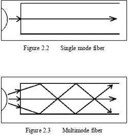
[image:24.612.202.452.361.627.2]For the medium of the communication link, the fiber optic will be used. Fiber optics also has two different types which are single mode fiber and multimode fiber. Single mode fiber is a fiber optic cable that can channel only one single light at a time. It has higher bandwidth and also higher transmission rate. This type of fiber is usually used in telephones and cable television applications. Figure 2.2 shows the ray propagation in the single mode fiber. The second type of fiber is multimode fiber. It is used to transmit many signals or lights per fiber. Multimode fibers also have different types which are graded index and step index. This kind of fiber is used in computer networks and LAN applications. Figure 2.3 shows the ray propagation in multimode fiber.
Figure 2.2 Single mode fiber