UNIVERSITI TEKNIKAL MALAYSIA MELAKA
A ANALYSIS AND SIMULATION OF FIBER TO THE HOUSE
(FTTH) AS AN ACCESS TECHNOLOGY IN FIBER OPTIC
COMMUNICATION LINK
This report submitted in accordance with requirement of the UniversitiTeknikal Malaysia Melaka (UTeM) for the Bachelor Degree of Electronic Engineering
Technology (Telecommunication) with Honours.
by
NOR AMIRA BINTI MAT KILA B071210294
930727-11-5572
ii
DECLARATION
I hereby, declared this report entitled “Analysis and Simulation of Fiber to the House (FTTH) As an Access Technology in Fiber Optic Communication Link.” is
the results of my own research except as cited in references.
Signature : ……….
Author’s Name : NOR AMIRA BINTI MAT KILA
v
ABSTRACT
vi
ABSTRAK
vii
DEDICATIONS
This humble effort specially dedicated to my beloved parents, family, lecturers and friends, whose love can never be forgotten for their support, guidance and
encouragement upon completing this project and report.
Special dedicated to my parents MAT KILA BIN ABAS
And
viii
ACKNOWLEDGMENTS
I would like to express my utmost appreciation to Mr. Chairulsyah Bin Wasli who is my final year project supervisor. The supervision and support that he gave truly help the progression and smoothness of completing this project. The co-operation is much indeed appreciated.
My grateful thanks also go to all lecturers who always give advices and motivate me to work harder and smarter.
ix
LIST OF SYMBOLS AND ABBREVIATIONS ... xv
CHAPTER 1 ... 1
1.0 Project Background ... 1
1.1 Problem Statement ... 2
1.2 Objective ... 2
1.3 Scope ... 2
1.4 Structure of Report ... 3
CHAPTER 2 ... 4
2.0 Introduction of Telecommunications ... 4
2.1 Copper cables ... 4
x
2.1.2 Unshielded Twisted Pair (UTP) ... 5
2.1.3 Shielded Twisted Pair (STP) ... 6
2.1.4 Comparing STP and UTP ... 7
2.2 Fiber optic ... 7
2.2.1 Fiber Optic Cable ... 8
2.2.1.1 Single mode fiber (SMF) ... 8
2.2.1.2 Multimode fiber (MMF) ... 9
2.3 Advantages to Choosing Fiber Over Copper Cable ... 10
2.4 Optical Network ... 12
2.4.1 Type of Optical Network ... 13
2.4.1.1 Active Optical Network (AON) ... 13
2.4.1.2 Passive Optical Network (PON) ... 14
2.5 Fiber to the Home ... 15
2.5.1 Fiber To The Home Architectures ... 16
2.5.1.1 FTTC (fiber to the curb) or FTTN (fiber to the node) ... 16
2.5.1.2 FTTW (Fiber to Wireless) ... 17
2.5.1.3 FTTH PON: Passive Optical Network... 18
2.5.1.4 FTTH installation ... 20
2.5.1.5 FTTH PON Types ... 21
2.6 Component of FTTH ... 23
2.6.1 Optical Line Terminal ... 24
2.6.2 Optical Splitter ... 24
xi
4.1.1 Power Budget for Fiber-Optic Cable ... 30
4.1.2 Power Margin for Fiber-Optic Cable ... 31
4.1.3 Cable loss ... 33
4.1.4 Insertion loss ... 34
4.1.5 Return loss ... 35
4.2 FTTH Simulation ... 35
4.2.1 The losses of cable based on the distance ... 36
4.2.2 The ratio of splitter and its losses ... 37
4.2.3 The power received based on the distance ... 38
xii
xiii
LIST OF FIGURES
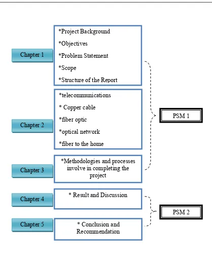
Figure 1.1: Structure of the Report ... 3
Figure 2.1: Coaxial Cable ... 5
Figure 2.2: Unshielded Twisted Pair (UTP) ... 5
Figure 2.3: Shielded Twisted Pair (STP) ... 6
Figure 2.4: A Fiber optic cable ... 8
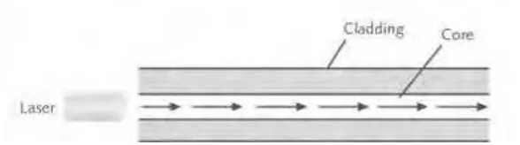
Figure 2.5: Transmission over single mode fiber optic cable ... 8
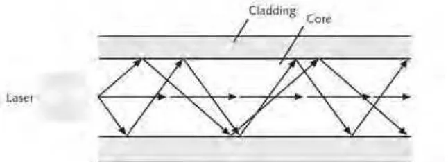
Figure 2.6: Transmission Over Multimode Fiber Optic Cable ... 9
Figure 2.7: Implementation of Active Optical Network (AON) ... 13
Figure 2.8: Implementation of Passive Optical Network (PON) ... 14
Figure 2.9: The Splitter ... 18
Figure 2.10: Two splitter ... 18
Figure 2.11: Fiber distribution system ... 20
Figure 2.12: Cable is underground ... 20
Figure 2.13: Network Interface Device Containing Fiber Optic Transmitters And Receivers ... 20
Figure 2.14: BPON architecture with analogue TV ... 22
Figure 2.15: Optical Line Terminal ... 24
Figure 2.16: Optical splitter ... 25
Figure 2.17: Optical Network Terminal ... 25
Figure 3.1: Flow Chart of Project Step ... 27
Figure 3.2: FTTH animation ... 28
Figure 3.3: Design of FTTH... 29
Figure 3.4: Simulation of FTTH ... 29
Figure 4.1: The simulation of FTTH by GUI matlab software ... 35
Figure 4.2: The graph of the distance versus cable loss ... 36
Figure 4.3: The graph the splitter loss versus number of user ... 37
xiv
LIST OF TABLE
Table 2.1: Comparison Single Mode Fiber & Multimode Fiber ... 10
Table 2.2: Loss in PON Coupler ... 19
Table 2.3: PON System Specification Summary ... 23
Table 4.1: Estimated Values for Factors Causing Link Loss ... 31
Table 4.2: Cable Loss Calculation ... 34
Table 4.3: Distance and Cable Loss. ... 36
Table 4.4: The splitter loss. ... 37
Table 4.5: The distance and received power ... 38
xv
LIST OF SYMBOLS AND ABBREVIATIONS
FTTH - Fiber-To-The-Home
CATV - Cable TV
UTP - Unshielded Twisted Pair PVC - Polyvinyl-Chloride
BER - Bit Error Rate ODN - Optical Distribution Network EFM - Ethernet In The First Mile
IEEE - Institute Of Electrical And Electronics Engineers PON - Passive Optical Network
CO - Central Office
OLT - optical line terminal ONU - optical network units
EPON - Ethernet-based Passive Optical Network FTTx - fiber to the x’
xvi DSL - digital subscriber line Wi-Fi - wireless fidelity
HDTV - High-definition television GEM - GPON encapsulation method WDM - wavelength division multiplexing ONT - Optical Network Terminals MAC - Media Access Controller GUI - Graphic user interface
PT - transmitter power
PB - power budget
PR - Power receiver
PM - Powe Margin
PB - Power budget
LL - Link Loss
1
CHAPTER 1
INTRODUCTION
1.0 Project Background
2
1.1 Problem Statement
Nowadays, in Malaysia, optical fiber is not fully developed in telecommunication link. Still copper cable is being used between the central office and the subscribers. When copper cable as the telecommunication link, it will be have a problem for people today. Because today it looks like everyone want high speed data, dependable voice service, and high quality video. The speed data was slow and low capacity of data will happen when we used the copper cable.
1.2 Objective
1) To gain more knowledge about FTTH through animation, calculation, design, and simulation.
2) Able to design FTTH network for specific area given.
1.3 Scope
1) Make a demonstration of FTTH in order to explain the FTTH as an access Technology in Fiber-Optic Communication Link by using animation.
3
1.4 Structure of Report
4
CHAPTER 2
LITERATURE REVIEW
2.0 Introduction of Telecommunications
The physical path over which the information flows from transmission to receive is called the transmission medium or the channel. Transmission media can be classified into two major categories: wired and wireless. Wired includes different types of copper and fiber optic cables, while wireless includes infrared, radio, microwave and satellite transmission. The performance specifications of cable are important when selecting a specific type of cable to determine its suitability for specific applications (Anu A. Gokhale).
2.1 Copper cables
5
2.1.1 Theory of Shape Based Matching Application
Figure 2.1: Coaxial Cable
Coaxial cable is a two-conductor cable in which one conductor forms an electromagnetic shield around the other; the two conductors are separated by insulation. This is a constant impedance transmission cable. It is primarily used for CATV since it provides a bandwidth of nearly 1GHz into the home. Coaxial cable is used for long distance, low attenuation, and low noise transmission of information (Anu A. Gokhale).
2.1.2 Unshielded Twisted Pair (UTP)
Figure 2.2: Unshielded Twisted Pair (UTP)
6
polyvinyl-chloride (PVC) or Teflon jacket. The twisting increase the electric noise immunity and reduces crosstalk as well as the bit error rate (BER) of the data transmission. UTP is a very flexible, low-cost media and can be used for either voice or data communications. Its greatest advantage is the limited bandwidth, which restricts long distance transmission with low error rates (Anu A. Gokhale).
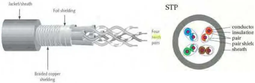
2.1.3 Shielded Twisted Pair (STP)
Figure 2.3: Shielded Twisted Pair (STP)
7
2.1.4 Comparing STP and UTP
The following list highlights their similarities and differences: 1. Throughput
STP and UTP can both transmit data at 10Mbps, 100Mbps, 1Gbps, and 10Gbps, depending on the grade of cabling and the transmission method in use.
2. Cost
STP and UTP vary in cost, depending on the grade of copper used. Typically STP is more expansive than UTP because it contains more materials and it has a lower demand (Tamara Dean).
3. Noise immunity
Because of the shielding, STP is more noise resistance rather than UTP. On the other hand signals transmitted over UTP may be subject to filtering and balancing technique to offset the effect of noise (Tamara Dean, 6th).
2.2 Fiber optic
8
2.2.1 Fiber Optic Cable
Figure 2.4: A Fiber optic cable
Fiber-optic cable, or simply fiber, contains one of several glass or plastic fibers at its cebter, or core. Data is transmitted via pulsing light sent from a laser or an LED (light emitting diode) through the central fibers. Surrounding the fiber is a layer of glass or plastic called cladding. The cladding has a different density from the glass or plastic in the strands. It reflects light back to the core in pattern that varies depending on transmission mode. This reflection allows the fiiber to bend around corner without diminishing the integrity of the light-based signal. Outside the cladding, a plastic buffer protects the cladding and core. Because the buffer is opaque, it also absorbs any light that might escape. To prevent the cable from stretching, and to protect the inner core further, strand of Kevlar (a polymeric fiber) surround the plastic buffer. Finally, a plastic sheath covers the strands of Kevlar. Fiber cable variations come into two categories: single mode and multimode (Tamara Dean, 6th).
2.2.1.1 Single mode fiber (SMF)
9
Single mode fiber (SMF) uses a narrow core (less than 10 microns in diameter) through which light generated by a laser travel over one path, reflecting very little. Because it reflects little, the light does not disperse as the signal travels along the fiber. This continuity allows single mode fiber to accommodate the highest bandwidth and longest distance (without requiring repeaters) of all transmission media. Single mode fiber may use to connect a carrier’s two facilities. However, it cost too much to be considered for used on typical LANs and WANs.
2.2.1.2 Multimode fiber (MMF)
Figure 2.6: Transmission Over Multimode Fiber Optic Cable
10
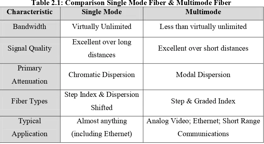
Table 2.1: Comparison Single Mode Fiber & Multimode Fiber
Characteristic Single Mode Multimode
Bandwidth Virtually Unlimited Less than virtually unlimited
Signal Quality Excellent over long
distances Excellent over short distances Primary
Attenuation Chromatic Dispersion Modal Dispersion
Fiber Types Step Index & Dispersion
Shifted Step & Graded Index Typical
Application
Almost anything (including Ethernet)
Analog Video; Ethernet; Short Range Communications
2.3 Advantages to Choosing Fiber Over Copper Cable
Fiber optic cable is one of the most popular mediums for both new cabling installations and upgrades, including backbone, horizontal, and even desktop applications. Fiber offers a number of advantages over copper.
1. Greater bandwidth
Fiber provides more bandwidth than copper and has standardized performance up to 10 Gbps and beyond. More bandwidth means fiber can carry more information with greater fidelity than copper wire. Keep in mind that fiber speeds are dependent on the type of cable used.
2. Speed and distance