UNIVERSITI TEKNIKAL MALAYSIA MELAKA
ANALYSIS AND SIMULATION OF SERVICE CONTINUITY
ENHANCEMENT BY USING AUTOMATIC PROTECTION
SYSTEM (APS) IN FIBER OPTIC COMMUNICATION LINK
This report submitted in accordance with requirement of the Universiti Teknikal Malaysia Melaka (UTeM) for the Bachelor Degree of Engineering Technology Bachelor’s Degree in Electronics Engineering Technology (Telecommunication) with
Honours
by
AHMAD TAQIUDDIN BIN AHMAD SARIMIN B071210253
900709-06-5383
i
DECLARATION
“I hereby declare that this report is result of my own effort except for works that
have been cited clearly in the references.”
Signature : ……….
Name : ....……….
ii
APPROVAL
“I hereby declare that I have read this report and in my opinion this report is sufficient in terms of the quality for Bachelor’s Degree in Electronics Engineering
Technology (Telecommunication) with Honours
………
iii
ABSTRACT
iv
ABSTRAK
v
DEDICATION
This project is dedicated to My dearest parent,
Ahmad Sarimin Bin Ahmad and Normayati Bte Abd Latef, All my siblings, and not forget to my friend, who have
Always sincerely pray for my success and glory. To my Supervisor,
Mr. Chairulsyah bin Abdul Wasli Thank you for your loving and
taught so that this task can be accomplished successfully
vi
ACKNOWLEDGEMENT
In the name of Allah S.W.T, The Most Beneficial and The Most Merciful. It is with deepest serve gratitude of the Al-Mighty that gives me strength and ability to complete this final year project report.
First of all, I would like to take this opportunity to express my special thanks to my supervisor, Mr Chairulsyah bin Abdul Wasli for the guidance, assistance, advise, kindness and also being helpful to guide me all the way through the development and progress of my final year project. Above all and the most needed, he provided me unflinching encouragement and support in various ways.
My appreciation also goes to my friends for their advice, supervision, and crucial contribution, which made them a backbone of this project to become successfully.
Thank you for lending hands during progress of the project.
vii
LIST OF ABBREVIATIONS …………...………...……… xiv
CHAPTER 1………...………..1
1. INTRODUCTION………...……….. 1
1.0. Background ………1
1.1. Problem Statement………..1
1.2. Objective……….1
1.3. Scope Of Works………..2
1.4. Expected results………. 2
CHAPTER 2………...………. 3
2. THEORETICAL BACKGROUND.…...………3
2.0. Introduction……….3
2.1. Introduction To Fiber Optic………...……….3
2.2. Fiber Optic Element In Communication System………5
2.3. Loss In Optical Communication System………8
2.4. Fiber Optic Link Failures………..10
2.5. Parameter in Fiber Optic………...11
2.6. Introduction To Automatic Protection Switch (APS)………...………11
2.7. APS Components………..13
viii
2.9. Parameters For APS System ……….14
2.10.Advantages And Disadvantages Of The APS System…………..………...16
2.11.Manufacturer For Switch Of APS………...……….16
CHAPTER 3………...………17
3. METHODOLOGY……...………... 17
3.0. Introduction………...17
3.1. Automatic Protection Switch Block Diagram………...………...17
3.1.1 Flowchart…………...……… 18
3.2. Animation………...………. 19
3.2.1 Procedure to make an animation………...…………..19
3.3. Design………21
3.3.1. Calculation………..21
3.3.2. Simulation………...21
CHAPTER 4………...………31
4. RESULTS AND ANALYSIS………...31
4.0. Introduction………...………31
4.1. Calculation Result And Analysis………...………...31
4.1.1. Output power………...………...31
4.1.2. Attenuation (dB)………...………..34
4.1.3. Signal Noise to Ratio (S/N)………...………….35
4.1.4. Insertion loss………...………... 36
4.1.5. Optical loss………..37
4.2. Simulation Result And Analysis………...38
4.2.1. Normal link………...………. 40
4.2.2. Backup link………...………. 40
4.3. Results Comparison………..42
4.4. Results Analysis And Discussion………...………. 43
CHAPTER 5………...………46
5. CONCLUSION AND RECOMMENDATION………46
5.0. Introduction………...46
5.1. Conclusion………46
5.2. Recommendation………..47
REFERENCES………...……… ...48
ix
LIST OF FIGURES
Figure 2.1: Structure of Fiber Optic………..4
Figure 2.2: Compact light source………..7
Figure 2.3: Photodetector……….8
Figure 2.4: Linear Scattering (reflection)………...………….…….8
Figure 2.5: Linear scattering………...………..8
Figure 2.6: Reyleigh Scattering of light………...……….9
Figure 2.7: APS Model………...………12
Figure 2.8: Single mode of APS………..………...12
Figure 2.9: Ring mode of APS………13
Figure 2.10: APS switch………..…….…..14
Figure 3.1: APS block diagram………...………17
Figure 3.2: Flowchart………..18
Figure 3.3: Insert Pose………..…….….20
Figure 3.4: Final Pose………..……...20
Figure 3.5: MATLAB interface………..……....22
Figure 3.6: GUI icon location………..….…..22
Figure 3.7: GUI template………...……….23
Figure 3.8: GUI interface………..….…….23
Figure 3.9: Interface after show all palette name………24
Figure 3.10: Push button………..……...24
Figure 3.11: Edit name location………..………....25
Figure 3.12: Callback location in GUI………..…….….25
Figure 3.13: Coding for Edit text at push button program files…………..…………26
Figure 3.14: Coding for recall or upload picture………..…….….26
Figure 3.15: Shown an axes that function to appearing a picture….……..…………27
Figure 3.16: Imported picture at GUI….………..…….….27
Figure 3.17: Aligns menu………..…….…28
Figure 3.18: Property inspector………...29
Figure 3.19: Static text………..…….29
Figure 3.20: Normal link simulation………..……30
Figure 3.21: Backup link simulation………..……30
Figure 4.1: Transmission data using main link…….………..…...32
Figure 4.2: Transmission data using backup link………..……32
Figure 4.3: Data transmission rate………..…...34
Figure 4.4: Optical Power………...37
Figure 4.5: Single Mode patch code………...39
Figure 4.6: Patch code connector………39
Figure 4.7: Interface normal link simulation….……….40
x
xi
LIST OF TABLES
Table 2.1: Advantages and Disadvantages of APS……….16
Table 4.1: Power conversion table………18
Table 4.2: Normal link output power…...………42
xii
LIST OF SYMBOLS AND ABBREVIATIONS
SNR = Signal Noise to Ratio
APS = Automatic Protection Switch
GUI = Graphical User Interface
PTX = Power Transmitter
PRX = Power Receiver
AC = Alternating current
LED = Light emitting diode
dB = Decibel
dBm = Decibel in Mill watts
ISI = Inter Symbol Interface
VAC = Volt Alternating Current
VDC = Volt Direct Current
ms = Millisecond
ST = Straight Tip
SC = Subscriber Connector
xiii
LIST OF APPENDIX
1
CHAPTER 1
INTRODUCTION
1.0 Background
The objective of this process is to protect the connections passing through the
failed fiber link once failure occurs. That means, routing the signals from the
switching node at one side of the failed fiber link to the switching node at the other
side of the failed fiber link using protection fibers. The APS process will restore the
connections that use the failed link in both directions. When the fiber link failed, the
failure is detected in the switching node on both sides of the failed link. Then, the
APS will take over the transmission link with a lower down time to avoid the data
lost. Besides that, when using the APS the failure link will be bypassed. However,
APS is not used continuously. When the damaged line was restored and repaired, the
transmission line will be automatically via the link to the original.
1.1 Problem Statement
Currently the down time in fiber optic communication link is still too long.
Thus, the down time will cause the data lose in communication. Therefore, we
need to provide the shortest time and also improve the communication system in
fiber optic. In order to solve this problem, APS is requested.
1.2 Objective
The main objective of this research are:
1 To analyse the continuity in Communication link of Fiber Optic using
Automatic Protection System (APS).
2
3 To improve knowledge about fiber optic communication link and
Automatic Protection System (APS)
4 To decrease the down time of Automatic Protection System (APS) in
fiber optic communication link.
1.3 Scope Of Works
The scope work for this project is to study the literature review about
Automatic Protection Switch (APS). Which is can be from reference book, article
and journal. Besides that, there are also to make and design a suitable animation
video to explain clearly about APS system. The animation will be use Adobe Flash
Cs6 software. Other than that, find out the related theoretical formula and make a
analyse the theoretical, simulation and measurement of the data that will get. The
data will find from references and practical works. After all the analyse has been
done, the process of thesis writing should be followed.
1.4 Expected results
The expected results from the recommended project:
(a) Enable to make attraction animation and capable simulation program.
(b) Simulation program of Automatic Protection System (APS).
3
CHAPTER 2
THEORETICAL BACKGROUND
2.0 Introduction
This chapter provides the literature review on the Automatic Protection
Switch system. It is about the process, the mechanism and the parameters that effect
the systems. This chapter also shows some of the manufacture that provides the
Automatic Protection Switch equipment.
2.1 Introduction to Fiber Optic
The field Optical fiber communication system has existed in the past decades.
Fiber optics is a part of modern communication systems, where it is very easy to find
along the roads, buildings, hospitals and others. The fiber itself is a strand of silica
based glass, its dimensions similar to those of a human hair, surrounded by a
transparent cladding. Light can be transmitted along the fiber over great distances at
very high data rates providing an ideal medium for the transport of information.
Besides that, optical fiber also able to carry light over long distance ranging from a
few inches to more than 100km with only little dimming. Cables that used such
fibers are commonly being chosen in certain types of communication link. There are
also have some single fibers that a thinner than human hair and measure less than
0.00015 inch (0.004 mm) in diameter.
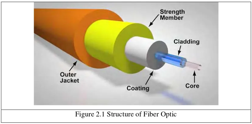
The diagram shows the typical structure of a fibre used for communication
links. It has an inner glass core with an outer cladding. This is covered with a
protective buffer and outer jacket. This design of fibre is light and has a very low
loss, making it ideal for the transmission of information over long distances. Figure
4
Figure 2.1 Structure of Fiber Optic
The light propagates along the fibre by the process of total internal reflection.
The light is contained within the glass core and cladding by careful design of their
refractive indices. The loss along the fibre is low and the signal is not subject to
electromagnetic interference which plagues other methods of signal transmission,
such as radio or copper wire links. The signal is, however, degraded by other means
particular to the fibre such as dispersion and non-linear effects (caused by a high
power density in the fibre core).
Light from a typical optical source will contain a finite spectrum. The
different wavelength components in this spectrum will propagate at different speeds
along the fibre eventually causing the pulse to spread. When the pulses spread to the
degree where they 'collide' it causes detection problems at the receiver resulting in
errors in transmission. This is called Inter symbol Interference (ISI). Dispersion
(sometimes called chromatic dispersion) is a limiting factor in fibre bandwidth, since
the shorter the pulses the more susceptible they are to ISI [Roshene McCool, 2010].
As part of a communication system, an optical transmitter will transmit
information in the form of light signals. The signals are generated by a light source
such as semiconductor laser or light-emitting diode (LED) at one end of the fiber and
detected by a light-sensitive device at the other end which called the receiver part. A
fiber optic cable can transmit much more information than an electrical type of cable
such as the copper cable at the same size. A major application of optical-fiber cable
5
network of fiber optic cables across the country and under the oceans to provide
information worldwide.
Fiber optic communication systems have many advantages that make them
more efficient than the old systems which used copper cable as the medium for
transmitting and receiving the data. One of the main advantages is they have a much
larger information-carrying capacity than copper cable. Fiber optic cable can carry
information signal larger than 10Giga bits per second. Other than that, fiber optic
cables are not bothered by electrical interference, and require fewer amplifiers than
copper-cable systems [Craig Freudenrich, Ph.D , 2009]. This will save the budget in
designing the optical communication link. Other advantages in fiber optic
communications link is fiber optic have larger bandwidth over a long distance. Like
that has been stated earlier, fiber optic can carry high capacity information signal.
The increasing of the capacity will increase the frequency and it shows that fiber
optic have larger bandwidth. Generally, fiber optic has bandwidth larger than 400
MHz per km but coaxial cable only has fewer MHz per km.
2.2 Fiber Optic Element in Communication System
For gigabits and beyond gigabits transmission of data, the fiber optic
communication is the ideal choice. This type of communication is used to transmit
voice, video, telemetry and data over long distances and local area networks or
computer networks. A fiber Optic Communication System uses light wave
technology to transmit the data over a fiber by changing electronic signals into light.
Some exceptional characteristic features of this type of communication
system like large bandwidth, smaller diameter, light weight, long distance signal
transmission, low attenuation, transmission security, and so on make this
communication a major building block in any telecommunication infrastructure. The
subsequent information on fiber optic communication system highlights its
characteristic features, basic elements and other details [Tarun Agarwal , 2010].
There are three main basic elements of fiber optic communication system.
They are:
6
3. Photo Detector
Accessories like connectors, switches, couplers, multiplexing devices,
amplifiers and splices are also essential elements in this communication system.
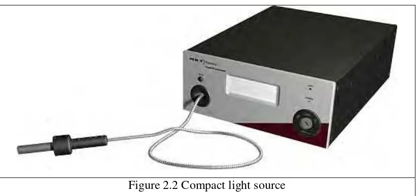
1. Compact Light Source
Depending on the applications like local area networks and the long haul
communication systems, the light source requirements vary. The requirements of the
sources include power, speed, spectral line width, noise, ruggedness, cost,
temperature, and so on. Two components are used as light sources: light emitting
diodes (LED’s) and laser diodes.
The light emitting diodes are used for short distances and low data rate
applications due to their low bandwidth and power capabilities. Two such LEDs
structures include Surface and Edge Emitting Systems. The surface emitting diodes
are simple in design and are reliable, but due to its broader line width and modulation
frequency limitation edge emitting diode are mostly used. Edge emitting diodes have
high power and narrower line width capabilities [Tarun Agarwal , 2010].
For longer distances and high data rate transmission, Laser Diodes are
preferred due to its high power, high speed and narrower spectral line width
characteristics. But these are inherently non-linear and more sensitive to temperature
variations.
Nowadays many improvements and advancements have made these sources
more reliable. A few of such comparisons of these two sources are given below. Both
these sources are modulated using either direct or external modulation techniques.
7
Figure 2.2 Compact light source
2. Low Loss Optical Fiber
Optical fiber is a cable, which is also known as cylindrical dielectric
waveguide made of low loss material. An optical fiber also considers the parameters
like the environment in which it is operating, the tensile strength, durability and
rigidity. The Fiber optic cable is made of high quality extruded glass (si) or plastic,
and it is flexible. The diameter of the fiber optic cable is in between 0.25 to 0.5mm
(slightly thicker than a human hair).
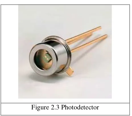
3. Photo Detectors
The purpose of photo detectors is to convert the light signal back to an
electrical signal. Two types of photo detectors are mainly used for optical receiver in
optical communication system: PN photo diode and avalanche photo diode.
Depending on the application’s wavelengths, the material composition of these
devices vary. These materials include silicon, germanium, InGaAs, etc.
This is all about the basic elements of the fiber optic communication system.
For additional information, and for any kind of assistance, please write to us as we
encourage and appreciate your suggestions, feedback, queries and comments [Tarun
8
Figure 2.3 Photodetector
2.3 Loss in Optical Communication System
Each of system in communication, it’s have they loss by its own. For this
fiber optic communication system, they are have two types of loss. Firstly is a linear
scattering losses and secondly are absorption losses.
Linear scattering losses have two types which is Rayleigh scattering losses
and MIE scattering losses.
Linear scattering losses is a about the propagation of light through the core of
an optical fiber which is based in total internal reflection of the light wave. Other
than that, rough and irregular surfaces even at the molecular level, can cause light
rays to be reflected in random directions. This is called diffuse reflection or
scattering, and it is typically characterized by wide variety of reflection angles [Craig
Freudenrich, Ph.D , 2009]. Figure 2.4 and 2.5 below shown the linear scattering in
fiber optic cable.
9
Figure 2.5 Linear Scattering
Light scattering also depends on the wavelength of the light being scattered.
Basically, scattering losses are caused by the interaction of light with density
fluctuations within a fiber. Density changes are produced when optical fibers are
manufactured.
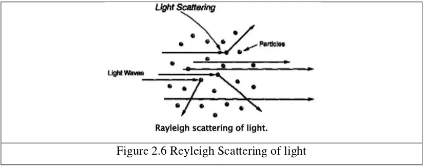
Rayleigh scattering is an atoms and other particles inevitably scatter some of
the light that hits them. The light isn’t absorbed, just sent in another direction in a
process. Figure 2.6 below shown the example of Rayleigh scattering of light.
Figure 2.6 Reyleigh Scattering of light
MIE scattering means if the size of the defeat is greater than one-tenth of the
wavelength of light. It also caused by these large defects in the fiber core, scatters
light out of the fiber core.
The method to remove the losses of scattering is a removed imperfections due
10
fiber and lastly increase the fiber guidance, which depends on refractive index
difference [Craig Freudenrich, Ph.D , 2009].
Second loss that will get in fiber optic communication link are absorption.
Absorption is a major cause of signal loss in an optical fiber. Besides that, it’s also
defined as the portion of attenuation resulting from the conversion of optical power
into another energy form, such as heat.
2.4 Fiber Optic Link Failures
The failure classes that are associated with fiber optic networks are classified
as patch panel failures, installation failures, and construction failures [Engr Dr Mrs
G.N Ezeh and Okwe Gerald Ibe, 2013].
Patch panel failures are failures that create malfunctions in the system by
high attenuation. Poor connection points can cause some of these malfunctions when
the fiber was terminated with the appropriate connectors. When the fiber is spliced
together poorly the signal inside the fiber optic cable can have large dB losses. If the
connections were not inserted in the connectors correctly or the fiber cable has
fractured parts in the glass, there can be very high attenuation to no signal
propagation into other parts of the communication network. This is going to possibly
show communication outages within the system. Installation failures are associated
with failures that are caused when installing the fiber optic network. If a fiber optic
cable is bent past the specification bending radius of the cable then the cable can fail
instantly or could possible fail over time. This might not be an automatic failure as
mentioned but could be failures later in time as the fiber optics weaken. This mainly
happens when the installer is not aware of the specification of the cable and not
paying attention to what he or she is doing.
Failures in fiber optics can also be caused by improper dressing and from
terminating the fiber optic connections. This kind of installation failure is sort of an
overlap from a patch panel failure. When fiber optic cable connections are terminated
to the cable poorly, weather it be ST connectors, SC connectors or similar connectors
for example, these cables can present a point of failure in the installation process.
Terminating fiber optic cable can be a very hard skill to master.
The last failure class is the failures that are related to the construction of the