Abstrak
–
In this article, basic concepts and general procedures in induction motor design and optimization are described. Beginning with the definition of design problem, some design objectives are distinguished based on the type of power supplies as well as motor applications. Some basic equations relating output characteristics to motor physical dimensions are given and two different design approaches are highlighted. The design optimization is explained by giving the definition of design variables and parameters, objective functions, constraint functions and the general technique of optimization. As examples, two motor designs with special objectives, including loss-minimization as well as wide speed-range operation, are presented.Keywords: energy saving, design, optimization, induction motor
I. INTRODUCTION
The purpose of a motor design is to determine
motor dimensions which satisfy a given set of
specifications under certain constraints and be
economical to achieve certain desired
performances [Ramarathnam, 1969]. The
constraints are commonly determined either by
consumers or by certain norms authorities. The
constraints demanded by consumers are for
examples the horse-power rating, efficiency,
power factor and full-load speed, whereas
those required by certain norms are for
instance the starting current, temperature rise
and starting torque. The designer tries to
satisfy all those requirements while
simultaneously trying to minimize the
material, production and operating costs in
general.
Designing a motor to be used with constant voltage and frequency supplies will be different to that using variable voltage and frequency supplies. Motor design for the use with current-source inverter will also be different from that with voltage-source inverter.
The objectives can also be distinguished depending on whether the motor will be used for load under constant or variable speed operations. Even if the design
Rini Nur Hasanah is with the Electrical Engineering Departement of Universitas Brawijaya, Malang, Indonesia (corresponding author provide phone 0341-665144; email [email protected])
principles are the same, the final configurations could be very different.
Conventionally-supplied motor design concerns the motor design for use with constant voltage and frequency supplies. Such motor is appropriate for constant speed load application. Designing motor for this application will confront various limitations required by norms authorities. The important thing to avoid is for example the high starting current, as it will burden the local power grid when direct on-line starting is carried out. Starting torque must also be considered in order to be able to drive load.
In some applications intended for energy saving, optimum-speed operation and increasing productivity, variable-speed drive systems are required. For such applications, motor design must be adapted for use with variable voltage and frequency supplies. In this design category, some limitations found in the previous conventionally-supplied motor design can be removed, for instance the starting current and torque. Different consideration on starting current limitation gives different view on the treatment of skin effect, for example. Unlike in the preceding category where the skin effect is important to reduce the starting current and to increase the starting torque, it is to be reduced for application with variable voltage and frequency motor design. The breakdown torque consideration is important when motor will be operated under constant power along wide speed-range zone.
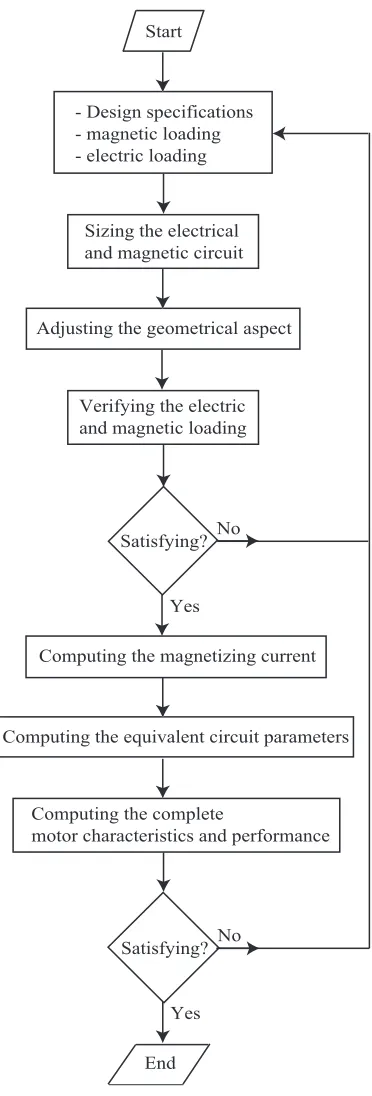
II. GENERAL PROCEDURES TO DESIGN AMOTOR As designing a motor means the finding of a suitable geometry, manufacturing data and performance indexes for given specifications, it comprises the steps of dimensioning (synthesis), sizing, and performance assessment (analysis). General procedure to design a motor includes the following design aspects:
• geometric, • electric, • magnetic, • mechanical, • and thermal aspects.
It is commonly begun by determining the desired specifications of the motor. The assigned magnetic and electric loadings are used to size the magnetic and electric circuits, which consists in adjusting the geometrical data to provide the needed flux and current densities. When they are not fulfilled yet, all dimensions
Energy Saving Through Design Optimization Of
Induction Motors
must be readjusted and the design process must be restarted until the desired values are obtained.
The coming after stages consist in finding the equivalent circuit parameters to calculate the motor characteristics and performance. If they are still not satisfactory, the whole design process must be repeated with new design values. Repeating the whole process is done according to an adopted strategy until the desired specifications are met or a satisfactory performance is obtained.
The flowchart of a general procedure to design a motor is shown in Fig. 1.
A. Basic Concepts And Design Constraints
One of the important indications in designing an electric machine is the relation between its dimensions to its output power.
The apparent power developed in an m-phase induction motor can be expressed as [Hamdi, 1994]:
(
)
( )
o
2
ws ts phS
=
m
π φ
f
k
N
I
(1)where
m
phases numberf
supplying frequency [Hz]ts
N
series turn-number per phaseph
I
phase current [A]φ
magnetic flux per pole [Wb]ws
k
winding factorThe frequency
f
can be expressed in terms of pole-pairs numberp
and synchronous speeds
n
: sf
=
p n
(2)The series turn-number per phase
ts
N
in terms of total conductor numbersN
tot is expressed as:tot
ts
2
N
N
m
=
(3)so that (1) becomes:
( )
o s ws tot ph
2
NS
=
π
p n k
φ
I
(4)As in general there is only one circuit per phase in small motors, the conductor current
cond
I
is the same as the phase currentph
I
.- Design specifications - magnetic loading - electric loading
Sizing the electrical and magnetic circuit
Yes No
End Satisfying?
Start
Adjusting the geometrical aspect
Verifying the electric and magnetic loading
Computing the magnetizing current
Computing the equivalent circuit parameters
Computing the complete
motor characteristics and performance
Yes No Satisfying?
Figure 1. Motor design flowchart.
The average flux density over the air gap of the machine, usually called the specific magnetic loading, can be expressed as:
is g_av
2
p
B
d l
φ
π
=
(5)where
d
isis the stator bore diameter.
The number of stator ampere conductors per meter of the stator periphery at the air gap, usually called the
is tot cond s
N
I
A
d
π
=
(6)Finally, the active power output equation is obtained by substituting (5) and (6) into (4) which results in:
o is2 s
o
P
=
C d
l n
(7)where
C
o is called the output coefficient:2
g_av s ws
o
1.11
cos
C
=
π
B
A k
η
ϕ
(8)with
η
is the efficiency andcos
ϕ
is the power factor.As shown with (7), the output coefficient relates the motor output power to its active parts volume and speed. It is proportional to the product of specific magnetic and electric loadings.
The specific magnetic loading determines the magnetization requirements of the machine. It influences the maximum flux density in the iron parts, magnetising current and core losses.
The specific electric loading determines the electric circuitry requirements in the machine. It influences the temperature rise that can be withstood by the machine, the required insulation material and the operating voltage of the machine.
B. Motor Design Methods
Generally, two methods to design a motor are known. The first one is undertaken based upon an available comparable design, whereas the second method is done by taking advantage of commercial motor design software. Some software producers claimed that their products could be useful even for an inexperienced designer; yet, using both methods, the experience of the designer and his ability to take important decisions at various stages of design to large extent are still required.
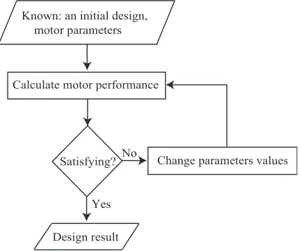
Classical method
Using the classical method, the design steps to follow are shown in Fig. 2. A previously existing motor design is used as a base design. Starting from it, motor performances and characteristics are calculated. As long as they do not correspond to the desired ones, motor parameters values are changed. Some iterations are sometimes needed before the satisfying performances are finally obtained.
State-of-the art method
It is a matter of designing motor with the help of a design and optimization commercial software. The design optimization software exempts the designer from bulky programming tasks and automates lots of the design processes. The designer is just required to model his design in an approximate analytical model representing technical and economical nonlinear heavily constrained problems.
As an example, the software Pro@DESIGN
[www.designprocessing.com] can compute large models with hundreds of equations and parameters. It consists of the following modules:
• Pro@DESIGN-Generate analyzes the model, and
generates automatically a compute object (COB) representing the model, including the formal exact sensibility information. This compute object, without any programming, is generated in seconds.
• Pro@DESIGN-Compute is a solver that computes
the outputs values according to the inputs to validate the model, and helps to do a sensibility analysis.
• Pro@DESIGN-Optimize finds an optimum using
the data and the constraints entered into the specification sheet by the sizing designer. It finds an optimum with a high performance SQP gradient-based algorithm, which is ideal for non-linear constrained problems typical to engineering, using the sensibility information.
• Pro@DESIGN-Optimize post-processor gives
tables and graphs to analyze the optimization results.
The design optimization software is very helpful in designing process, however up to a certain extent the initial guess values, which sometimes determines the reasonable results, are still dependent on the designer expert knowledge. Even so, the Pro@DESIGN enables the designer to focus his time and talent more in its modeling expertise to find better solutions, create better models, or work on more designs.
III. MOTOR DESIGN OPTIMIZATION
Motor design optimization is essentially a problem solving involving nonlinear programming techniques. It can be one of minimizing the cost, weight, volume, etc. being subjected to a set of constraints, while almost all of these functions being nonlinear.
Known: an initial design, motor parameters
Calculate motor performance
Yes No
Design result
Satisfying? Change parameters values
Figure 2. Designing a motor based upon a comparable motor design.
A. Objective Of Optimization
achieve a desired performance under some imposed constraints. It is usually formulated as a general nonlinear programming problem and intended to find:
1
,
2,...
nwith
0
x
=
x x
x
x
≥
(9)such that:
f k x
(
1
,
)
is minimum (maximum)
(10)
being subjected to:
(
1)
i
,
0
1, 2,3,...
g k x
≤
i
=
r
(11)(
1)
i
,
0
1, 2,3,...
h k x
=
j
=
s
(12)A maximizing problem can always be regarded as a minimizing one by using the negative of the objective function
f k x
(
1
,
)
, so that optimizing then means finding the optimal value of variables containing in the vector x, which give the minimum value off k x
(
1
,
)
and satisfy the given constraintsg k x
i(
1,
)
and(
1)
j
,
h k x
.B. Design Variables And Parameters
Design variables are entities that identify a particular design and will change over a prescribed range during the search for the optimal design [Venkataraman, 2002]. A specific design is characterized with the values of a complete set of these variables. This set is identified as the design vectorx, as shown in (9).
In order to apply the techniques of optimization, the choice of the set of design variables must meet the criterion of linear independence, even in a complex design where the linear relationship may not be very apparent.
Design parameters identify constants which will not change as different designs are compared. They are primarily predetermined constants in the design, so that they have no principal role to play in determining the optimal design [Venkataraman, 2002]. The set of design parameters is identified as k1.
C. Objective Function
Objective function (10) establishes mathematical model of the design problem and drives the search for the optimal design. The objective functions must be composed, explicitly or implicitly, of the design variables. It can be a single objective function or alternatively multi-objective functions. In the single objective function,
f k x
(
1
,
)
has a scalar value. The multi-objective functions drive the search for the optimal design using several different design functions, which could be either conflicting or cooperating objectives. In multi-objective functions,f
(
k x
1
,
)
is avector.
The objective function could represent for example the production cost, annual cost, capitalized cost, efficiency, efficiency, weight, volume, etc.
D. Constraint Functions
The constraint functions could be either inequality constraints
g k x
i(
1,
)
or equality constraints(
1)
j
,
h k x
. They could represent the performance properties of the motor, the dimensional and other additional requirements.
The inequality constraints for example are the locked-rotor current, the starting torque, the temperature rise, etc, whereas the equality constraints can be the motor power rating for example.
E. Optimization Techniques
Optimization techniques are basically composed of objective function calculation and its corresponding constraints verification. This technique is carried out by repeating the whole process until sufficient convergence is reached using any deterministic or stochastic optimization mathematical method. The optimization is usually performed with the help of software programs and requires significant computer resources.
Three main prerequisites to do an optimization are:
•
mathematical modeling of the design
problem,
•
knowledge of computer programming,
•
knowledge of optimization techniques.
Nowadays there are available some special-purpose optimization software packages, exempting a designer from an obligation for bulky computer programming or even to search for the optimization techniques, as provided by ProDesign for example. Some other softwares provide ready-to-use optimization functions, for example Matlab and MathCad. However, the core of the optimization is still the appropriate mathematical modeling of the design problem.
IV. DESIGNING MOTOR WITH SPECIAL OBJECTIVES
A. First Case: Minimizing Losses
As an application example of motor design and optimization, minimizing losses objective will be taken. The influence of various design parameters on the objective value will be observed with the help of
ProDesign design and optimization software.
The design variables to be used are stator bore diameter d, stator stack length la, stator slot depth des, stator slot width wes, stator core depth dcs, rotor slot depth der, rotor slot width wer, air gap flux density Bg, end ring width wring, end ring depth dring and air gap length gap.
fixed during each design and optimization realization. The losses to be minimized are assumed to be consisted of the stator and rotor joule losses and the stator teeth and core losses.
1) Equivalent circuit parameters
In order to express losses in terms of the design variables, motor equivalent circuit parameters must be found in terms of the design variables. They are consecutively given in (15) – (43).
Number of turns in series per phase: Ns
Stator winding resistance per phase:
(
)
Rotor resistance per phase:
(
)
(
ring)
a
r Rr1 2 Rr2
er er ring ring
a g
Slot leakage reactance:
(
)
slot1 es er
a
slot 2 slot2 slot3
es er
Zigzag leakage reactance:
(
)
divided equally in the stator and rotor parts, which gives the following value:(
)
ls lr slot end skew zigzag
1
2
X
=
X
=
X
+
X
+
X
+
X
(36)
The stator teeth and core losses are expressed in terms of the design variables as follows.
Fe
The core loss resistance can be expressed as:
Rc
The stator and rotor Joule losses are expressed in terms of the design variables as follows.
(
)
The total losses are expressed as:
P
Loss=
P
Js+
P
Jr+
P
ts+
P
cs (49)2) Constraints
As constraints, starting torque, maximum torque and starting current are used. Their functions are given as
Starting rotor current:
Starting air gap induced voltage:
2 2
r rstart
indstart lr
E
=
I
R
+
X
(53)Starting stator current:
indstart indstart obtained by minimizing losses while confining the starting and maximum torques as well as starting stator current between some limiting values.
Table 1 The final values during losses minimization iterations
Design variables Final Values
Stator bore diameter d 0.03415 Iron core length la 0.04
Starting current 1.347
Starting torque 0.6833
Maximum torque 0.8029
In this case, less losses are accompanied with less starting and maximum torques. When motor is to be used in a wide speed-range operation, the maximum value obtained is very important to consider. It is because the motor sometimes needs to develop a torque with value almost approaching its maximum torque to drive its load.
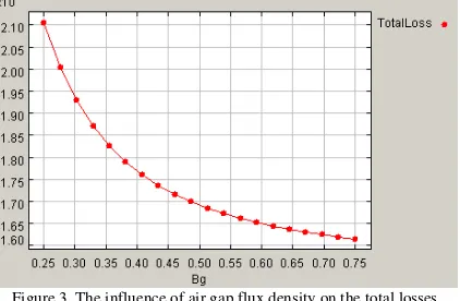
Using a software like ProDesign, the influence of each design variable on the objective value can be observed easily. As shown in Fig. 3, when only the influence of air gap flux density on the total losses is to be observed, higher the air gap flux density is, less will be the obtained losses.
Figure 4 The influence of air gap flux density on each component of losses
The influence of stator bore diameter on the total losses is shown in Fig. 5.
Figure 5 The influence of stator bore diameter on the total losses As shown in Fig. 6, such form of curve is caused principally by the decreasing rotor Joule losses and the increasing stator Joule losses.
Figure 6 The influence of stator bore diameter on each component of losses
If we let all design variables change while putting the starting and maximum torques as well as stator starting current as constraints, the losses minimization iterations are shown in Fig. 7. The iterations of the stator teeth and core losses are shown in Fig. 8, whereas those of the stator and rotor Joule losses are given in Fig. 9.
B. Second Case: Adjustable-Speed Motor Design
The use of induction motor in a variable-speed drive-system is more and more common and desirable
nowadays. This trend is being strengthened mainly by the advances in power- and micro-electronics technology together with those in the field-oriented control methods. An appropriate combination of inverter supply-system and field-oriented control method will give the induction motor a better opportunity to get more and more important roles in adjustable-speed drive-systems.
The required speed and torque characteristics of an induction motor are determined by the type of its application. In an application requiring a wide speed-range, the use of field-weakening method is advisable. However, for a given set of induction motor parameters, its torque and speed capability are limited by the maximum values of inverter current and voltage used.
Figure 8 Stator teeth and core losses iterations during losses minimization
1) Operating characteristics
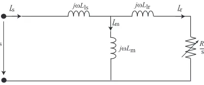
In order to design a motor being capable of working in a wide speed-range using an inverter supply voltage, the conventional motor equivalent circuit, where all parameters are referred to stator, should be rearranged to form its associated rotor flux-based equivalent circuit in order to facilitate the field oriented performance study. Other assumptions, where the stator winding resistance, iron saturation and losses are neglected, are taken.
Rearranging the steady-state induction motor equivalent circuit into the rotor flux-based one to nullify the series inductance in rotor branch is derived in the following paragraphs.
The original conventional equivalent circuit without stator resistance and magnetizing resistance is shown in Fig. 10.
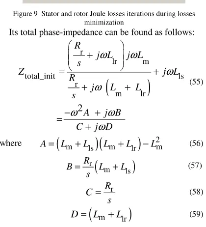
Figure 9 Stator and rotor Joule losses iterations during losses
minimization
Its total phase-impedance can be found as follows:
(
)
r
lr m
total_init ls
r
m lr
2 =
R
j L j L
s
Z j L
R
j L L
s
A j B
C j D
ω
ω
ω
ω
ω
ω
ω
+
= +
+ +
− +
+
(55)
where
(
m)
(
m)
2mls lr
A= L +L L +L −L (56)
(
)
r
m ls
R
B L L
s
= + (57)
r
R C
s
= (58)
(
m lr)
Rr
Figure 10 Induction motor equivalent circuit with ignored stator and magnetizing resistances
With all leakage inductances being referred to the rotor flux, the equivalent circuit becomes:
R'r
Figure 11 Induction motor equivalent circuit with all leakage inductances being referred to the rotor flux
Its associated total phase-impedance can be expressed as follows: developed torque can be stated as:
o the inverter are expressed as:
2 2 2
For various operating conditions, the required torque-producing stator-current components as a function of flux-producing stator-current component are as follows:
• constant-torque operation: T
• constant-current condition:
2 2
T N
I
=
I
−
I
(73)• constant-voltage condition:
(
)
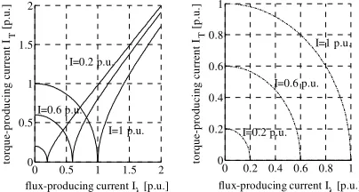
The constant-torque operation results in a hyperbolic curve of torque-producing current as a function of flux-producing current, as shown in Fig. 12.
The relation between the torque-producing and flux-producing current components under operation with constant-current condition results in a form of circle
Figure 12 Various constant-torque operating conditions
the left part of Fig. 13. The right-part of Fig. 13 shows the relation when the imaginary part is ignored.
0 0.5 1 1.5 2
flux-producing current Iλ [p.u.]
to
flux-producing current Iλ [p.u.]
to
Figure 13 Various constant-current operating conditions
Under constant-voltage operation the torque-producing current component as a function of flux-producing current component forms an ellipse with
centre (0,0) and an ellipticity
o imaginary values are replaced with their corresponding absolute values. The right-part of Fig. 14 represent (74) when the imaginary values are ignored.
0 0.5 1 1.5 2
flux-producing current Iλ [p.u.]
ω=1 p.u.
Figure 14 Various constant-voltage operating conditions
At the onset of the field-weakening operation, both limiting current-and-voltage values are attained. Using (69), (73) and (74), the torque as a function of stator ignored in the right-part of Fig. 15.
2) Design characteristics
To fulfill the need of a variable-speed drive system, actually the standard motors designed for general purpose constant frequency application can often be
used on adjustable frequency controllers. However, a motor which is designed for best performance on a single frequency is not the optimum motor for use on an adjustable-frequency system. If a high performance level of the system is imperative, either the controller or the motor should be designed specifically.
The advance in power-electronic technology and its ever-increasing development are almost always able to fulfill such an expectation. On the other side, the inherent complexity of induction motor design makes the achievement in this case is not so advanced as that of the control side.
stator angular frequency [p.u.]
fl
stator angular frequency [p.u.]
Figure 15 Flux-weakening torque as a function of stator angular frequency
Contrary to the common practice, where the working characteristics of a motor are obtained from a given set of motor and drive inverter, in order to obtain an appropriate motor being capable of working and resulting the desired characteristics, motor design should consider the volt-ampere rating of the driving inverter [Bianchi, 1997].
If B
α is the current vector angle representing the angle formed by the torque- and flux-producing current components at rated condition and being chosen during the drive design, the limiting inverter current as a inverter current value.
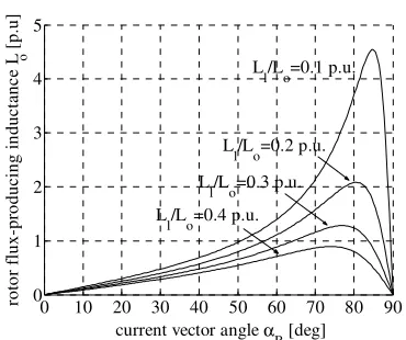
Fig. 17 shows the values of total inductance
L
o being responsible for the flux production as a function of current vector angle for some values of o0 10 20 30 40 50 60 70 80 90
current vector angle α B [deg]
Figure 16 Limiting inverter current as a function of current vector angle for various o
l/
Figure 17 Total inductance being responsible for the flux production as a function of current vector angle for various
o maximum flux-weakening frequency is. The right-part of Fig. 18 is obtained by ignoring the imaginary values of torque, whereas the left-part is obtained by taking their corresponding absolute values.
Influence of current-vector angle
α
Bon the field-vector angle is smaller.0 1 2 3 4 5 6
stator angular frequency [p.u]
fl
stator angular frequency [p.u]
Ll/Lo [p.u.]
Figure 18 Field-weakening torque as a function of angular frequency for various o
l/
stator angular frequency [p.u] stator angular frequency [p.u]
fl
Figure 19 Field-weakening torque as a function of angular frequency for various values of current vector angle
B
• the choice of current vector angle
B
α is determined from the desired design characteristics:
o high torque-capability is obtained with a low value of
B
α , but with higher motor size (lower inductance
o
L
) and lower power-factor (higher inverter current-rating3) Design procedure
must be adopted because in this operating region the nominal voltage of the driving inverter would have been attained. Increasing the speed beyond that rated condition can be realized by weakening the flux while maintaining the supply-voltage at its nominal value. Consequently, the required motor parameters and the volt-ampere ratings of the driving inverter must be determined to meet the need.
Steps to design an induction motor being capable of working in the field-weakening region are as follows:
1) Determine the desired field-weakening performance
• the flux-weakening torque
T
FW• the flux-weakening angular frequency
FW
ω
2) Determine the required ratio of total leakage inductance to rotor-flux producing inductance
o l
/
L
L
and the current vector angle at base conditionα
B3) Calculate the required inductance corresponding to rotor-flux production o
L
, the total leakage inductanceL
l and the inverter current ratingI
N4) Determine the base operating values of the desired motor: the base torque, the base angular frequency, the base voltage, the base current and the base inductance
5) Find the peak stator current and the motor inductance
6) Choose the poles number, maximum stator tooth flux density, maximum stator iron yoke flux density, the stator slot height, stator slot-width, winding coefficient and number of stator slots per pole per phase.
V. CONCLUSION AND OUTLOOK
In this article, a global view on how to design induction motor is described. Beginning with the description of design problem, various different objectives based on the types of supply as well as loads to drive are given. Basic concepts and a general procedure to design a motor is followed with the description of two common motor design methods, the classical one being based on a previously available design and the state-of-the art method involving the use of commercial design including optimization software. It can be concluded that using both methods, up to a certain extent the experience of the designer is still required at various design stages. It is still unconceivable to have an independent, unique and general program being capable to do the design job completely and giving satisfactory results.
Completing the motor design, optimization is necessary. Beginning with determining the objective of optimization, an objective function to optimize along
with its associated constraint functions must be built using the design variables and parameters. The objective along with the constraint functions must be resolved using some known optimization techniques. To solve the optimization problem, some commonly used optimizing algorithms are available. Some known calculation softwares, for example Matlab, MathCad, etc., provide ready-to-use optimizing functions based on some commonly known algorithms. Design software with optimizing capability, for example ProDesign, is also available commercially. Optimization included design software forms the state-of-the art design method. The key in optimization, which is also the difficulty at the same time, resides at the construction of objective and constraints functions using the design variables and parameters. It is not always easy to construct a group of independent equations in order that the optimization algorithm can be applied appropriately.
The description of energy saving through motor design optimization in this article is completed with some examples of design with special objectives. An induction motor design with minimized losses has been taken as a case example. The description of how to design an induction motor being operated in an adjustable speed environment has also been presented.
VI. ACKNOWLEDGEMENTS
The author would like to thank The Swiss Federal Commission of Scholarship and The Integrated Actuators Laboratory of the Ecole Polytechnique Fédérale de Lausanne for having financed and made possible the accomplishment of my researches some results of which are presented in this article.
BIBLIOGRAPHY
[1] Bianchi, N. and Bolognani, S. (1997) “Design procedure of a vector controlled induction motor for flux-weakening operations”, Conference Record of the Thirty-Second IAS Annual Meeting, IEEE Industry Application Conference, IAS’97., Volume:1, Page(s):104-111.
[2] _________. (1997). “Parameters and volt-ampere ratings of a field-oriented induction motor drive for flux-weakening applications”, Eight International Conference on Electrical machines and Drives. Conf. Publ. No. 444, Page(s): 46-50. [3] Hamdi, E.S. (1994). Design of Small Electrical Machines, New
York: John Wiley & Sons Inc.
[4] Ramarathnam, R. (1969). Optimization of Polyphase Induction Motor Design. Bombay: IIT Master of Technology Thesis. [5] Venkataraman, P. (2002) Applied Optimization with MATLAB