COMPENSATION LOW-FREQUENCY ERRORS IN TH-1 SATELLITE
Jianrong Wang a,b,*, Renxiang Wang a, Xin Hu a aXi’an Institute of Surveying and Mapping, Xi’an, China–
Faculty of Geo-Information Science and Earth Observation (ITC) of University of Twente, Enschede, The Netherlands – [email protected]
Commission WG I/4
KEY WORDS: Satellite photogrammetry, Low-frequency errors, Attitude determination system, Exterior orientation elements, Location accuracy, Global coverage
ABSTRACT:
The topographic mapping products at 1:50,000 scale can be realized using satellite photogrammetry without ground control points (GCPs), which requires the high accuracy of exterior orientation elements. Usually, the attitudes of exterior orientation elements are obtained from the attitude determination system on the satellite. Based on the theoretical analysis and practice, the attitude determination system exists not only the high-frequency errors, but also the low-frequency errors related to the latitude of satellite orbit and the time. The low-frequency errors would affect the location accuracy without GCPs, especially to the horizontal accuracy. In SPOT5 satellite, the latitudinal model was proposed to correct attitudes using approximately 20 calibration sites data, and the location accuracy was improved. The low-frequency errors are also found in Tian Hui 1 (TH-1) satellite. Then, the method of compensation frequency errors is proposed in ground image processing of TH-1, which can detect and compensate the low-frequency errors automatically without using GCPs. This paper deal with the low-low-frequency errors in TH-1: First, the analysis about low-frequency errors of the attitude determination system is performed. Second, the compensation models are proposed in bundle adjustment. Finally, the verification is tested using data of TH-1. The testing results show: the low-frequency errors of attitude determination system can be compensated during bundle adjustment, which can improve the location accuracy without GCPs and has played an important role in the consistency of global location accuracy.
* Corresponding author
1. INTRODUCTION
Satellite photogrammetry is not only an important method to obtain geospatial data, but also an effective way to realize the mapping for no-map regions or difficult areas. In the last century, the proposal was put forward in MAPSAT project, which the topographic mapping products at 1:50,000 scale could be realized without ground control points (GCPs) using the high accuracy of exterior orientation elements (Itek, 1981). The standards for mapping at 1:50,000 scale are also given, in which the horizontal accuracy is 12 m (RMSE), the vertical accuracy is 6 m (RMSE) and the contour interval (CI) is 20 m (Itek, 1981). The standards are called MAPSAT Engineering Standards (MSES) in this paper. Though the MAPSAT satellite was not developed due to the high stability of the satellite platform, the design has a good reference and a profound impact on subsequent photogrammetry satellite.
Many countries, such as Germany, France, Japan and India, had developed optical photogrammetry satellite system with “global coverage on a continuous basis” (Itek, 1981), and researched on location accuracy without GCPs (Ebner et al., 1991, 1999; Breton et al., 2002; Bouillon et al., 2002; Srinivasan et al., 2008). However, the location accuracy of some satellites did not reach the MSES without GCPs after the accuracy testing within the scope of the global, and the direction of horizontal had systematic errors (Gruen et al., 2007; Gupta et al., 2008). In SPOT5 satellite, Bouillon et al. (2003) found that the systematic errors of position may be caused by in-flight time and latitude using star tracker (STT), and proposed the latitudinal model (Bouillon et al., 2003) to correct attitudes using approximately
20 calibration sites distributed worldwide. Applying the latitudinal model, the location performance of HRS is improved from 63 m to 33 m (distance for 90% of the measures) (Bouillon et al., 2003).
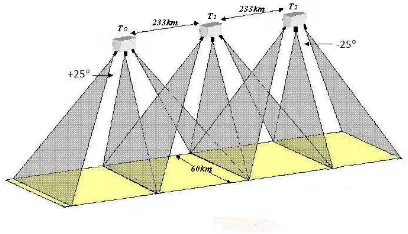
The Tian Hui 1 (TH-1) is the first stereo mapping transmission satellite in China, and its goal is for topographic mapping at 1:50,000 scale without GCPs (Wang Renxiang et al., 2013). 1st, 2nd, and 3rd satellite of TH-1 was launched on August 24, 2010, May 6, 2012, and October 26, 2015. TH-1 is placed in a 500 km sun synchronous orbit, and its payloads are constituted with Line-Matrix CCD (LMCCD) camera (Wang Renxiang et al., 2004) with 5 m resolution, high resolution camera with 2 m resolution and multispectral camera with 10 m resolution. The ground swath width of all cameras is 60 km. The LMCCD camera is composed of three-line arrays CCD camera and four small matrix array cameras. The three-line arrays CCD camera includes forward, nadir and backward camera, which the forward and backward camera are pointing 25 ahead and 25 behind along the track, and stereoscopic images are acquired in a single pass (see Figure 1). The base-to-height ratio is about 1. In addition, the Global Positioning System (GPS) and three STTs are configured to get the initial exterior orientation elements. During the ground processing, the low-frequency errors of the attitude determination system are also founded in TH-1. In this paper, the analysis about low-frequency errors of the attitude determination system is performed, compensation models are proposed in bundle adjustment and the verification is tested using data of TH-1.
Figure 1. Stereoscopic images acquisition process
2. COMPENSATION LOW-FREQUENCY ERRORS OF
ATTITUDE DETERMINATION SYSTEM 2.1 Phenomenon of low-frequency errors
During TH-1’s first year in orbit, there was a mistake about the attitude determination system, which the coordinate system should be J2000.0 (Davies et al., 1995), but another was given. This made location accuracy getting worse with time change. Thus, the correction models were put forward to deal with the problem (Wang Renxiang et al., 2011). Finally, the problem was found using correction models, and the location accuracy became reasonable using right coordinate system. The correction models not only resolve the mistake successfully, but also are the theoretical foundation of the low-frequency errors compensation in EFP bundle adjustment.
After resolving the problem of coordinate system, there are existing systematic changes in the angles between two STTs. Wang Xintao et al., (2004) analysed the data of STTs using the angle method, and found the angle changes between the main optical axis of two STTs. The changes is 60, and has an obvious periodicity within a period of 1.5 hours (about one orbital period), and is closely related with the position of the sun. As a result, exterior orientation elements involve the angle changes, which would lead to large errors of position without GCPs.
2.2 Compensation low-frequency errors in EFP bundle adjustment
The technology of location accuracy without GCPs is a complex system, which involves payloads, platform of satellite, pattern of photography, strategy of stereoscopic ground cover, and so on. The bundle adjustment of three-line arrays image is used to solve the orientation of image, which can refine the exterior orientation parameters. The Orientation Image (OI) bundle adjustment (Hofmann, 1986) and EFP bundle adjustment (Wang Renxiang, 2006) are two methods for three-line arrays image. However, they cannot solve the high location accuracy without GCPs in optical satellite photogrammetry with “global coverage on a continuous basis”. Then, the EFP Multi-functional bundle adjustment (Wang Jianrong et al., 2012) was developed in TH-1 satellite, which can process stereo images of whole three intersection areas (Wang Renxiang et al., 2014), low-frequency errors, and drift angle correction (Wang Jianrong et al., 2014).
Using EFP bundle adjustment, the exterior orientation elements
orientation parameters of each three-line arrays image are expressed as polynomial functions of the parameters at the neighboring orientation points. During calculation, the space resection and forward intersection are alternately iterative with smooth conditions of exterior orientation elements, until vertical parallax reach minimum.
Due to the low-frequency errors, the attitudes of initial exterior orientation elements include systematic changes of low-frequency errors. Analysed many data of TH-1, the systematic changes are mainly representing in the direction of pitch and yaw, which can be equivalent to the angle corrections from STT frame to nadir camera after on-orbit calibration. The errors of
where
f
= principal distancey
= linear length across track
= intersection angle between forward and nadir camera (or between backward and nadir camera)q
= average value of vertical parallax of all tie points at EFP timeThe vertical parallax is caused not only by the low- frequency errors of pitch and yaw, but also by the random errors of exterior orientation elements. During the EFP bundle adjustment, the average value of vertical parallax of all tie points can weaken the influence of random errors. Then
and
are the main factors to cause the systematic vertical parallax, and are calculated using Equation (1) and (2). The attitudes of exterior orientation elements are corrected with
and
, and participate the bundle adjustment again. Thus, the bundle adjustment needs to be calculated iteratively until the vertical parallax reaches minimum and the changes of vertical parallax is below a predetermined value (1 pixel in TH-1).Usually, there are three angles of attitude determination system including pitch, roll and yaw, and the changes of pitch and yaw can be calculated using vertical parallax. As to the errors of roll, it is difficulty to compensate by vertical parallax. Fortunately, the changes of roll are little and almost unchangeable after on-orbit calibration. Based on these, the models of compensation low-frequency errors are established, and the low-frequency errors of pitch and yaw are detected and corrected automatically in EFP bundle adjustment, which is the main function of EFP Multi-functional bundle adjustment.
3. COMPENSATION TESTING OF LOW-FREQUENCY
ERRORS
the on-orbit calibration of geometric parameters. After on-orbit geometric calibration of TH-1, the angle corrections from STT frame to nadir camera include the low-frequency errors of attitude determination system, and the latitude of calibration area can be seen as "zero" point of the low-frequency errors. So the image with maximum low-frequency errors is difficulty to occur near this latitude. Analysed from many data, the low-frequency errors may be caused by in-flight time and latitude. Thus, the tests are performed using different data of TH-1. The data include different time data at the same latitude of calibration area, and the data far away from the latitude of calibration area. All GCPs of tests are measured by GPS, and their accuracies are about 0.5 m in horizontal and vertical. GCPs are not participated the EFP Multi-functional bundle adjustment, and are only as Check Points to evaluate the location accuracy.
3.1 Detection of the low-frequency errors
In order to compensate the low-frequency errors, the first step is to detect the errors of pitch and yaw during the EFP Multi-functional bundle adjustment. According to the vertical parallax of all tie points, the low-frequency errors in the direction of the pitch and yaw can be detected automatically. The test was performed using the data far away from the calibration area, and the results are shown in the Figure 2.
Figure 2. Distribution of low-frequency errors in the direction of pitch and yaw
As seen from Figure 2, the length of route image is 300 km, and the errors of pitch and yaw are calculated and presented in systemic, especially in the direction of the yaw. The errors of yaw are about 40, and the maximum error of pitch is about 10. Usually, the errors of pitch and yaw, calculated automatically, also include the high-frequency errors of exterior orientation elements, and the change of errors is not a constant (see Figure 2). However, the major errors of pitch and yaw can be corrected by a value (such as 40 of yaw in this route), and the residual errors are processed during the bundle adjustment.
3.2 Different time data at the same latitude of calibration area
The test data were acquired on the June 2012 from 2nd of TH-1, and geometric parameters were calibrated at May 2012, and test data is near the latitude of calibration area. Based on on-orbit calibration parameters, the forward intersection and EFP Multi-functional bundle adjustment are performed. The vertical parallax and the compensation values of low-frequency errors are calculated without GCPs, and the location accuracy is assessed using Check Points. The results are shown in Table 1.
Type X Y h P Table 1. Statistics of location accuracy and compensation values
using two methods
In Table 1, the number of Check Points is 10. Type 1 is represented forward intersection using on-orbit calibration parameters and Type 2 is represented EFP Multi-functional bundle adjustment using on-orbit calibration parameters. X is forward intersection. After EFP Multi-functional bundle adjustment, the low-frequency errors of attitude determination system are compensated, in which
is 1.7 and
is 0.Though
is little, the P is improved about 3.6 m and vertical parallax reaches 0.3 pixel. The time between test data and calibration results is about one month at same latitude, and the compensation is little. With the time changes, especially changes in latitude, the values of
and
will be changed greatly. The test not only shows the relationship between the location accuracy and the low-frequency errors, but also validates the function of compensation low-frequency errors in EFP Multi-functional bundle adjustment.3.3 Different latitude data with calibration area
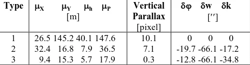
The test data were obtained from 1st of TH-1 at January 2012, and the geometric parameters were calibrated at October 2010. Test data and on-orbit calibration results are almost over one year and locate in different latitudes. After the EFP Multi-functional bundle adjustment using on-orbit calibration parameters, the compensation values of low-frequency errors and vertical parallax are listed in Table 2. The errors of horizontal location are distributed in Figure 3, and the changes of vertical parallax are shown in Figure 4.
Type X Y h P Table 2. Statistics of location accuracy and the compensation
values using three methods
Figure 3. Distribution the horizontal accuracy using different methods
Figure 4. Distribution the vertical parallax using different methods
In Table 2, Figure 3 and Figure 4, Type 1 is represented the forward intersection using laboratory calibration parameters, Type 2 is represented the forward intersection using on-orbit calibration parameters, and Type 3 is represented the EFP Multi-functional bundle adjustment using on-orbit calibration parameters. The number of Check Points is 15.
Seen from Table 2, Figure 3 and Figure 4, the horizontal accuracy is about 147.6 m with large systematic errors using laboratory calibration parameters, and can be improved to 36.5 m using on-orbit calibration parameters. However, the X is still large, which may be caused by the low-frequency errors of attitude determination system. After the EFP Multi-functional bundle adjustment, the low-frequency errors are calculated, in which
is 6.9 and
is 17.6, and the horizontal accuracy reaches 17.9 m from 36.5 m. In addition, the vertical parallax is large and presents the systemic in Type1 and Type2, and reaches 0.3 pixel after EFP Multi-functional bundle adjustment. Though the 17.9 m is not a desired result, it is obtained by the function of compensation low-frequency errors. From Figure 3 can be seen, the fifth Check Point may has a large error, which may lead to the result of 17.9 m.
4. CONCLUSION
Attitude determination system is an important parts of satellite photogrammetry, which is closely related to the location accuracy. The low-frequency errors of attitude determination system are founded in many satellites, such as SPOT5, TH-1. In this paper, we analyse the low-frequency errors in TH-1, compensation models are proposed and realized in EFP Multi-functional bundle adjustment, and the verification of compensation low-frequency errors is performed using different data of TH-1. The results indicate that with the proposed compensation models in EFP Multi-functional bundle adjustment, the low-frequency errors can be detected and compensated automatically without using GCPs. Finally, the location accuracy of TH-1 reaches the MSES and its
Noticing that the low-frequency errors are changed with in-flight time and latitude, and the compensation low-frequency errors will get good results based on-orbit calibration parameters. Thus, the geometric parameters of camera should be calibrated on-orbit in regular.
ACKNOWLEDGEMENTS
This study is funded by the China Scholarship Council (CSC). The first author thanks the Faculty of Geo-information Science and Earth Observation (ITC) of the University of Twente for providing a good research environment.
REFERENCES
Breton, E., Bouillon, A., Gachet, R., Delussy, F., 2002. Pre-flight and in-Pre-flight geometric calibration of SPOT5 HRG and HRS images. International Archives of the Photogrammetry, Remote Sensing and Spatial Information Sciences, 34(1), pp. 20-25.
Bouillon, A., Breton, E., De Lussy, F., Gachet, R., 2002. SPOT5 HRG and HRS first in-flight geometric quality results. Proceedings of SPIE - The International Society for Optical Engineering, Aghia Pelagia, Greece. Vol.4881, pp. 212-223.
Bouillon, A., Breton, E., De Lussy, F., Gachet, R., 2003. SPOT5 geometric image quality. Proceedings of 2003 IEEE International Geoscience and Remote Sensing Symposium, Vol. I (2003), pp. 303–305, Toulouse, France.
Davies, M. E., Abalakin, V. K., Bursa, M., Lieske, J. H., Morando, B., Morrison, D., Tjuflin, Y. S., 1995. Report of the IAU/IAG/COSPAR working group on cartographic coordinates and rotational elements of the planets and satellites: 1994. Celestial Mechanics and Dynamical Astronomy, 63(2), pp. 127-148.
Ebner, H., Kornus, W., Ohlhof, T., Putz, E., 1999. Orientation of MOMS-02/D2 and MOMS- 2P/Priroda imagery, ISPRS Journal of Photogrammetry and Remote Sensing, 54(5-6), pp. 332-341.
Ebner, H., Kornus, W., Strunz, G., Hofmann, O., Muller, F., 1991. A simulation study on point determination using MOMS-02/D2 imagery, Photogrammetric Engineering & Remote Sensing, 57(10), pp. 1315-1320.
Gruen, A., Kocaman, S., Wolff, K., 2007. Calibration and validation of early ALOS/PRISM images. The Journal of the Japan Society of Photogrammetry and Remote Sensing, 46(1), pp. 24-38.
Gupta, A., Nain, J. S., Singh, S. K., Srinivasan, T. P., Krishnaa, B. G., Srivastava, P. K., 2008. Long strip modelling for CARTOSAT-1 with minimum control point. ISPRS Volume XXXVII Part BI, Beijing.
ITEK corp. 1981. Conceptual design of an automated mapping satellite system (MAPSAT): Final technical report. Itek Optical System, Massachusetts.
Srinivasan, T. P., Islam, B., Singh, S. K., Krishna, B. G.,
Archives of the Photogrammetry, Remote Control and Spatial Information Sciences, 37.
Wang Renxiang, Hu Xin, Yang Junfeng, Wang xinyi, 2004. Proposal LMCCD camera for satellite photogrammetry. Acta Geodaetica et Cartographica Sinica, 33(2), pp. 116-120.
Wang Xintao, Li Yingchun, Li Xiaoyan, 2012. Mapping satellite-1 star sensor accuracy analysis. Journal of Remote Sensing, Vol.16, pp. 90-93.
Wang Renxiang, Hu Xin, Wang Jianrong, 2013. Photogrammetry of Mapping Satellite-1 without ground control points. Acta Geodaetica et Cartographica Sinica, 42(1), pp. 1-5.
Wang Renxiang, Wang Jianrong, Hu Xin, 2011. Study on the photogrammetry of in-flight satellite without ground control point. Geomatics and Information Science of Wuhan University, 36(11), pp. 1261-1264.
Wang Jianrong, Wang Renxiang, 2012. EFP multi-functional bundle adjustment of mapping satellite-1 without ground control points. Journal of Remote Sensing, Vol.16, pp. 112-115.
Wang Renxiang, Wang Jianrong, HU Xin, 2014. The EFP bundle adjustment of all three line intersection. Geomatics and Information Science of Wuhan University, 39(7), pp. 757-761.
Wang Jianrong, Wang Renxiang, Hu Xin, 2014. Drift angle residual correction technology in satellite photogrammetry. Acta Geodaetica et Cartographica Sinica, 43(9), pp. 954-959.