_______________________
A LIGHT-WEIGHT LASER SCANNER FOR UAV APPLICATIONS
A. M. G. Tommaselli a * F. M. Torres a a
Univ Estadual Paulista, Unesp, Presidente Prudente, São Paulo, Brazil – [email protected], [email protected]
Commission I, ICWG I/Va
KEY WORDS: Light-weight scanner, LiDAR, Point Cloud
ABSTRACT:
Unmanned Aerial Vehicles (UAV) have been recognized as a tool for geospatial data acquisition due to their flexibility and favourable cost benefit ratio. The practical use of laser scanning devices on-board UAVs is also developing with new experimental and commercial systems. This paper describes a light-weight laser scanning system composed of an IbeoLux scanner, an Inertial Navigation System Span-IGM-S1, from Novatel, a Raspberry PI portable computer, which records data from both systems and an octopter UAV. The performance of this light-weight system was assessed both for accuracy and with respect to point density, using Ground Control Points (GCP) as reference. Two flights were performed with the UAV octopter carrying the equipment. In the first trial, the flight height was 100 m with six strips over a parking area. The second trial was carried out over an urban park with some buildings and artificial targets serving as reference Ground Control Points. In this experiment a flight height of 70 m was chosen to improve target response. Accuracy was assessed based on control points the coordinates of which were measured in the field. Results showed that vertical accuracy with this prototype is around 30 cm, which is acceptable for forest applications but this accuracy can be improved using further refinements in direct georeferencing and in the system calibration.
1. INTRODUCTION
Unmanned Aerial Vehicles (UAV) have become widely accepted as a tool for aerial image acquisition due to their flexibility and favourable cost benefit ratio. Besides UAV, several other acronyms are being used to refer to this class of unmanned aerial vehicles. For a comprehensive review on Unmanned Aerial Systems (UAS) see Colomina and Molina (2014).
Most UAVs are being developed to carry an RGB camera with the purpose of acquiring images but lack accurate georeferencing. For some applications these UAVs with low cost RGB cameras are suitable but there are other problems demanding more sophisticated sensors. Examples of challenging applications for which ordinary imaging systems on-board UAVs are of limited value are forestry and environmental monitoring demanding high quality geometric and spectral information. Multi, hyperspectral cameras and laser scanners are among the sensors that can be used to collect more meaningful data in complex environments.
Forest management inventories (Hyyppä, 2011) is one application of Airborne Laser Scanning (ALS) due to several advantages offered by this technology, mainly pulse penetration in the canopy, a feature which can enable the reconstruction of the 3D structure of the forest. Commercial Airborne Laser Scanning systems, although powerful and highly accurate, are weighty and expensive, reducing the range of potential applications and users.
The use of laser scanning devices on-board UAVs is less common, and just a few commercial or experimental systems are available (Jaakkola et al., 2010; Wallace et al., 2012; Droeschel et al., 2013; Kuhnert and Kuhnert, 2013; Glennie et al., 2013; Esposito et al., 2014; RIEGL, 2016; YellowScan, 2016; UAV LidarPod, 2016). Petrie (2013) presented a review of commercial systems for UAVs.
These lightweight systems are highly flexible and can be used at low flight height providing dense cloud points over limited
areas. Several applications requiring laser scanning can use UAV-based platforms, which can offer more affordable and flexible solutions.
Low cost laser scanners usually have limited range and several restrictions, but they can be attractive, because they can be used at low flight height. Some of these lightweight and low cost devices were originally developed for other tasks, for instance, automatic car guidance, but they can be adapted for use as surveying instruments.
One of these devices is the IbeoLux 2010 scanner, from Ibeo Automotive Systems GmbH, originally produced for driving assistance (Ibeo, 2016). Several projects have already been developed with this hardware showing its feasibility for use as a UAV based scanner (Jaakkola et al., 2010; Wallace et al., 2012). Further improvements with reference to the existing experimental systems can strengthen the range of applications, for instance, the use of more suitable Inertial Navigation Systems and UAVs with more autonomy.
The aim of this paper is to present the main features of a light-weight laser scanner carried by a UAV and an assessment of the performance of this system both in accuracy and with respect to point density.
2. BACKGROUND
Lidar systems use the time-of-flight principle to compute distances and altimetry information. Lidar systems for altimetry measurement were first developed in the 1960s and 1970s. In the 1990s the development of scanning devices and technologies for high frequency determination of platform position and attitude made systems with the current configuration feasible (Shan and Toth, 2008).
A mobile laser scanning system has certain components: a Global Navigation Satellite System (GNSS) receiver and inertial measurement unit (IMU), providing platform position and attitude; a laser ranging unit, which sends and receives laser pulses and computes distances; the scanning mechanism which The International Archives of the Photogrammetry, Remote Sensing and Spatial Information Sciences, Volume XLI-B1, 2016
redirects laser pulses to known angles; electronic/computer components for control and data recording (Shan and Toth, 2008).
Ground coordinates of each point measured by the mobile laser scanner are computed with Eq. (1) which expresses the sum of two vectors (adapted from Habib et al. (2010)).
(1)
Where:
: Ground coordinates of point i;
: Coordinates of the GNSS antenna at an instant t;
: Rotation matrix relating the ground coordinates and the IMU coordinate system, derived after processing the GNSS and IMU data;
: Offset between the laser unit and IMU origin (lever-arm);
angles). For linear scanners there is only one angle (mirror rotation), whilst for the laser unit used in this research measured during the acquisition process but at different frequencies and time systems. Synchronizing all the devices to the same time reference is a fundamental task to avoid systematic errors and is usually performed with pulses provided by the GNSS receiver and with events fed back by the scanner and recorded by the GNSS receiver. Regardless of the frequency of acquisition of position and attitude, interpolation of this information for each received laser pulse instant is required for the computation of point coordinates with Eq. (1).
According to Habib et al. (2010) some elements of the scanning system have to be determined in a calibration process, which is performed in several steps: (1) Laboratory calibration; (2) platform calibration and; (3) In-flight calibration. For commercial systems, the laboratory calibration process estimates the offset and orientation angles between the laser unit and the IMU. In-flight calibration uses control features to refine these parameters with in-situ data.
There are several techniques to calibrate the laser system parameters (offsets, boresight and biases in the mirror angles and ranges) and they are based on the assessment of the discrepancies in the coordinates of control features or surfaces generated by the laser system and the corresponding ground values determined by a more accurate technique.
There are two main groups of calibration techniques: (1) system driven calibration, based on physical models, requires raw measurements such as distances, scanning angles, position and attitude for each pulse; (2) data driven compensation, when the resulting data (point clouds) is refined with strip adjustment (Habib et al., 2010).
Experimental systems, such as the one presented in this paper, have the advantage of gathering access to all raw data. The offset between the laser unit and IMU origin can be directly measured with surveying techniques but the boresight angles require an indirect estimation process with an in-flight calibration step. The general concept is based on Eq. (1) in which the boresight angles are left as unknowns and solved based on control points, control features or common features between strips (Habib et al., 2010; Lee et al., 2007; Habib et al., 2010).
Some experimental light-weight laser scanning systems were developed to be carried by UAVs achieving good results. Jaakkola et al. (2010) presented what can be considered the first light-weight system, which was based on IbeoLux laser scanning, a Sick LMS laser profiler, SPAN-CPT navigation system, a spectrometer, a CCD camera, carried by a UAV helicopter, which was tested for tree measurements.
Wallace et al. (2012) developed a similar system, but performed experimental assessment with both a Hokuyo (30LX) and a Sick LD-MRS-400001 scanner.
The system used in our work has components similar to those already referenced. The Inertial Navigation System (INS) has not been used in other systems and also the UAV has more autonomy to perform longer flight lines and cover wider areas. These components will be detailed in the next section.
3. INTEGRATING A LIGHT-WEIGHT LASER SYSTEM
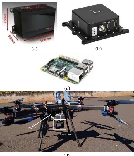
The light weight laser scanner system integrated at Unesp has four major components: (1) an IbeoLux 2010 laser scanner; (2) a recording unit; (3) an Inertial Navigation System Novatel IGM-S1 and; (4) the UAV octopter (Fig. 1).
The IbeoLux 2010 scanner, from Ibeo Automotive Systems GmbH, was originally developed to assist driving. This unit has two laser emitters and four independent receivers arranged in a line. The scanning mirror is planar with a reflexive surface on both sides resulting in four parallel scan lines, two of which scanned each time. The laser unit also enables the recording of 3 echoes per pulse and the reflected pulse width. The scan frequency can be chosen from 12.5 Hz, 25Hz or 50 Hz. The horizontal range is 85º (which can be extended to 110º) and the vertical range is 3.2º (Ibeo Automotive Systems, 2016). The measurable distance ranges from 0.3 m to 200 m and the distance resolution is 4 cm.
Raw laser data is grabbed in a Raspberry PI portable computer, along with binary data from the INS for later post-processing.
This laser unit was integrated with a light-weight Inertial Navigation System Span-IGM-S1, from Novatel, to be used both on UAVs and mobile terrestrial platforms. The INS provides both time stamps for scanner synchronization via PPS The International Archives of the Photogrammetry, Remote Sensing and Spatial Information Sciences, Volume XLI-B1, 2016
and NMEA and raw GNSS and IMU data that are externally recorded for later post processing.
The UAV octopter was developed by a third partner company (Sensormap Geotecnologia, 2016) with aircraft aluminium and carbon fibre, ensuring a light structure. Tests performed ensured that the UAV can fly for 30 minutes with a payload of 5 kg.
(a) (b)
(c)
(d)
Figure 1. Main components of the light-weight laser scanner system (a) laser scanner; (b) INS; (c) Raspberry PI; (d) UAV
octopter.
INS data is processed with Inertial Explorer software to provide positions and attitudes and the binary raw file from IbeoLux is converted to a CSV file providing GNSS time, angles, distances and pulse(s) widths. From this data, cloud points are generated and assessed. Laser scanner data has to be processed to filter the raw data with previously established restrictions to validate the values recorded in the CSV file. Some values were not consistent with the valid values for the layer, echo, pulse width, distances measured and scan angles according to the specifications of the laser scanner and the operational configurations.
Lever arm components were directly measured from specifications provided with the equipment and boresight misalignment angles between the INS and laser unit were indirectly estimated from control points located both in point clouds and in the area.
4. EXPERIMENTAL ASSESSMENT AND RESULTS
Two flights were performed with an UAV octopter carrying the equipment. In the first trial, the flight height was 100 m with six strips over a parking area. Fig. 2.a shows an aerial view of the area and Fig. 2.b a sample profile containing a building from the resulting point clouds from several flight strips. Fig. 2.c presents the Digital Surface Model (DSM) generated from the resulting point cloud with 1 meter of spacing and Fig. 2.d shows a profile of one strip of the area.
(a) (b)
(c)
(d)
Figure 2. (a) Area covered; (b) point cloud profile sample containing a building; (c) MDS from the resulting point cloud (d) Sample point cloud generated from the scanning device data
of one single strip.
Few pulses were recorded in some areas due to the low reflectance received by the laser unit from the black pavement for this flight height. The returning pulses over vegetation areas were acceptable and with this data it was feasible to compute point clouds which will be useful to estimate average tree height.
Finding distinguishable control points in this area for quality control and estimation of boresight angles is troublesome. For this reason, boresight angles were considered to be negligible and were not estimated in this experiment. The effects of these angles are small for low flight height, as was previously studied by Wallace et al. (2011) and, consequently, the altimetry accuracy will be acceptable. The laser scanner angular accuracy is 0.25° and the ranging accuracy is 0.1 m, as specified by the manufacturer.
According to Jaakkola et al. (2010) and Wallace et al. (2012) the noise caused by the resolution and accuracy of the laser scanner pose great difficulty when calibrating the system accurately. Also, the laser spot size is wider in the horizontal direction.
An altimetry quality control was performed based on 9 Ground Control Points (GCP) distributed over the parking area (Table 1) and a relative quality control was also performed based in the estimated rooftop corners (Fig. 2.b) of a building observed in point clouds generated from two flight strips (Table 2). The high horizontal errors observed at corner points can be explained by uncertainty in the identification of the corner points in these point clouds.
Mean 0.112 m Standard Deviation 0.176 m
RMSE 0.201 m
Table 1. Altimetry errors computed from 9 GCP.
ΔX (m) ΔY (m) ΔZ (m)
Mean 0.166 0.014 -0.153
Standard Deviation 0.647 0.697 0.164
RMSE 0.602 0.623 0.212
Table 2. Errors estimated from 4 corner points of a rooftop.
This experiment showed a poor pulse return from the asphalt pavement at flight heights above 80 m and some problems with attitude estimation at strip changes. Even so, the altimetry accuracy is around 20 cm for a flight height of 100 m, which was compatible with that achieved by other authors, but at lower flight heights.
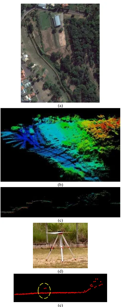
The second trial was carried out over an urban park with some
buildings to serve as reference targets (Fig. 3.a). In this experiment a flight height of 70 m was chosen to improve target response. Fig. 3.b shows the resulting point cloud and Fig. 3.c a profile containing an isolated building and a sample with dense vegetation.
Some flat targets constructed with 90x90 cm square panels, installed over tripods (Fig. 3.d) were distributed in flat areas in such a way that they could be identified in point clouds only by slope change (Fig. 3.e). Additional targets on the scene were also used to enable both boresight estimation and accuracy assessment. Accuracy was assessed based on ground control points at which coordinates were obtained by relative GNSS surveys.
Some targets could not be identified in point clouds due to the point density obtained. The discrepancies for the identified targets are shown in Table 3.
(a) Errors estimated with 3 strips: 2, 12 and 13 with 4 GCP ΔX (m) ΔY (m) ΔZ (m)
Mean -0.047 0.632 -0.32
Standard Deviation 0.488 0.814 0.501
RMSE 0.454 0.984 0.564
(b) Errors estimated with 2 strips: 2 and 13 with 4 GCP
Mean 0.198 0.053 0.038
Standard Deviation 0.447 0.493 0.308
RMSE 0.435 0.430 0.270
Table 3. Errors for 4 GCPs measured in point clouds: in (b) strip 12 was removed from the data.
The analysis from the errors from the GCPs showed a systematic effect in Y and Z components of strip 12, and this discrepancy was around 0.90 m in altimetry. Eliminating the measurements from this strip data, the RMSE was around 0.4 m in planimetric components and 0.27 m in heights (Table 3, last row).
Computing and applying the boresight correction with measurements from GCPs on strips 2 and 13 reduced the errors in planimetric components to 0.213 m in X, 0.321 m in Y and 0.294 m in altimetry.
(a)
(b)
(c)
(d)
(e)
Figure 3. (a) Second trial area; (b) resulting point cloud; (c) lateral profile containing an isolated building; (d) target
example, and (e) its identification in point cloud.
The density of the point clouds and points reaching the terrain was assessed for some sample plots in both areas. In the first flight, three 5 x 5 m sample plots over a vegetation area with Eucalyptus were assessed. The average point density was 45 points per sample (1.8 points/m2) of which 19 are points that reached the ground surface. For the second area, 3 plots The International Archives of the Photogrammetry, Remote Sensing and Spatial Information Sciences, Volume XLI-B1, 2016
(5 x 5 m) were also selected but over dense vegetation, and the average point density was 129 points per sample (5 points/m2) of which about 11 reached the ground. These figures show that this system is suitable for forest studies in dense vegetation areas.
5. CONCLUDING REMARKS
This paper presents a light-weight laser scanning system. The accuracy and point density achieved with this light-weight system was assessed with flights performed in two areas with different configurations. Results showed that vertical accuracy with this prototype is around 30 cm, which is acceptable for forest applications.
Further refinement can be achieved by using alternative techniques for laser scanning calibration such as those presented by Habib et al. (2010) and Habib et al. (2010b). It is planned to make some improvements in the hardware with a second GNSS receiver to compute heading and more accurate time synchronization. Nevertheless, the potential of this system is encouraging because of its flexibility, accuracy and costs.
ACKNOWLEDGEMENTS
The authors would like to acknowledge the support of FAPESP (Fundação de Amparo à Pesquisa do Estado de São Paulo - grant 2013/50426-4), CNPq (Conselho Nacional de Desenvolvimento Científico e Tecnológico - grant 307554/2014-7) and CAPES (Coordenação de Aperfeiçoamento Pessoal de Nível Superior - grant 307554/2014-7). The authors are also tankful to FGI (Finnish Geospatial Institute), Eija Honkavaara and Anttoni Jaakkola for their kind support for this project development.
REFERENCES
Colomina, I., and P. Molina. 2014. Unmanned Aerial Systems for Photogrammetry and Remote Sensing: A Review. ISPRS Journal of Photogrammetry and Remote Sensing, 92, pp. 79–97.
Droeschel, D., M. Schreiber, and S. Behnke. 2013. Omnidirectional perception for lightweight UAVs using a continuously rotating 3d laser scanner. In: International Archives of the Photogrammetry, Remote Sensing and Spatial Information Sciences, Vol. XL-1/W2: pp. 107–12.
Esposito, S., M. Mura, P. Fallavollita, M. Balsi, G. Chirici, A. Oradini, and M. Marchetti. 2014. Performance Evaluation of Lightweight LiDAR for UAV Applications. In: Geoscience and Remote Sensing Symposium (IGARSS), 2014, IEEE International, pp. 792–95.
Glennie, Craig, Benjamin Brooks, Todd Ericksen, Darren Hauser, Kenneth Hudnut, James Foster, and Jon Avery. 2013. Compact Multipurpose Mobile Laser Scanning System — Initial Tests and Results. Remote Sensing, 5 (2), pp. 521-538.
Habib, A., A. P. Kersting, K. I. Bang, and D. C. Lee. 2010. Alternative Methodologies for the Internal Quality Control of Parallel LiDAR Strips. IEEE Transactions on Geoscience and Remote Sensing, 48 (1), pp. 221–36.
Habib, A., K. I. Bang, A. P. Kersting, and J. Chow. 2010b. Alternative Methodologies for LiDAR System Calibration. Remote Sensing, 2 (3), pp. 874-907.
Hyyppä, J. 2011. State of the Art in Laser Scanning. In: Photogrammetric Week 2011, pp. 203–216.
Ibeo Automotive Systems. 2016. Accessed April 5. http://www.ibeo-as.com/.
Jaakkola, A., J. Hyyppä, A. Kukko, X. Yu, H. Kaartinen, M. Lehtomäki, and Y. Lin. 2010. A Low-Cost Multi-Sensoral Mobile Mapping System and Its Feasibility for Tree Measurements. ISPRS Journal of Photogrammetry and Remote Sensing, 65(6), pp. 514–522.
Kuhnert, K.-D., and L. Kuhnert. 2013. Light-weight sensor package for precision 3d measurement with micro UAVs e.g. power-line monitoring. In: International Archives of the Photogrammetry, Remote Sensing and Spatial Information Sciences, Vol. XL-1/W2, pp. 235–240.
Lee, J., K. Yu, Y. Kim, and A. F. Habib. 2007. Adjustment of Discrepancies Between LIDAR Data Strips Using Linear Features. IEEE Geoscience and Remote Sensing Letters, 4 (3), pp. 475–79.
Petrie, Gordon. 2013. Current Developments in Airborne Laser Scanners Suitable for Use on Lightweight UAVs: Progress Is Being Made!. GEOInformatics, 16 (8), pp. 16.
RIEGL - Unmanned Scanning. 2016. Accessed April 5. http://www.riegl.com/products/unmanned-scanning/.
Sensormap Geotecnologia. 2016. Accessed April 5. http://www.sensormap.com.br/.
Shan, Jie, and Charles K Toth. 2008. Topographic Laser Ranging and Scanning: Principles and Processing. CRC press.
UAV LidarPod. 2016. Routescene. Accessed April 5. http://www.routescene.com/products/product/uav-lidarpod/.
Wallace, L, A Lucieer, D Turner, C Watson, and others. 2011. Error Assessment and Mitigation for Hyper-Temporal UAV-Borne LiDAR Surveys of Forest Inventory. In: Proceedings of SilviLaser 2011, 11th International Conference on LiDAR Applications for Assessing Forest Ecosystems. University of Tasmania, Australia, pp. 1–13.
Wallace, L., A. Lucieer, C. Watson, and D. Turner. 2012. Development of a UAV-LiDAR System with Application to Forest Inventory. Remote Sensing, 4 (6), pp. 1519-1543.
YellowScan - Ultra-Light Scanners for UAVs and Light Aircrafts. 2016. YellowScan. Accessed April 5. http://www.yellowscan.fr/.