CHALLENGES AND POTENTIALS USING MULTI ASPECT COVERAGE OF URBAN
SCENES BY AIRBORNE SAR ON CIRCULAR TRAJECTORIES
S. Palma,b∗, N. Pohla, U. Stillab
a
Fraunhofer FHR, Institute for High Frequency Physics and Radar Techniques, 53343 Wachtberg, Germany - (stephan.palm, nils.pohl)@fhr.fraunhofer.de b
Institute for Photogrammetry, Technische Universitaet Muenchen, Muenchen, Germany - [email protected]
KEY WORDS:Airborne Circular Synthetic Aperture Radar, UAV, Urban Scenario, FMCW SAR, Multi Aspect Microwave Imaging
ABSTRACT:
Airborne SAR on small and flexible platforms guarantees the evaluation of local damages after natural disasters and is both weather and daylight independent. The processing of circular flight trajectories can further improve the reconstruction of target scenes especially in complex urban scenarios as shadowing and foreshortening effects can be reduced by multiple views from different aspect angles (hyper- or full- aspect). A dataset collected with the Miranda 35 GHz radar system with 1 GHz bandwidth on a small ultralight aircraft on a circular trajectory over an urban scene was processed using a time domain approach. The SAR processing chain and the effects of the navigational data for such highly nonlinear trajectories and unstable platforms are described. The generated SAR image stack over the entire trajectory consists of 240 individual SAR images, each image visualizing the scene from a slightly different aspect angle. First results for the fusion of multiple aspect views to create one resulting image with reduced shadow areas and the possibility to find hidden targets are demonstrated. Further potentials of such particular datasets like moving target indication are discussed.
1. INTRODUCTION
To evaluate local damages after natural disasters, remote sensing requires flexible platforms and sensor systems to guarantee inde-pendence from both weather and sunlight. Radar sensors on small manned or unmanned airplanes are well suited for those charac-teristics. Due to low energy consumption, small size and light weight millimeter-wave FMCW radar sensors are very promis-ing for this task. Together with the miniaturization of inertial measurement units, operational high resolution SAR systems are currently on the scale of some kilograms (Palm et al., 2014), (Ot-ten et al., 2014), (Kinghorn and Nejman, 2009). Typically, image generating radar systems depend on the SAR principle, which requires a side looking geometry. Especially in urban environ-ments, this geometry causes shadowing and foreshortening ef-fects, which lead to gaps in the reconstructed scene and often to misinterpretation (Stilla et al., 2003). This is particulary true if there is no digital elevation or digital surface model used dur-ing the focussdur-ing process to reduce foreshortendur-ing through im-proved ground height estimations. Multiple views from different aspect angles can reduce the shadowing effects for reconstruction of roads or digital surface models, but in unknown urban areas, the best line of sight cannot be investigated in advance (Stilla and Hedman, 2010), (Schmitt and Stilla, 2011). Compared with the classical methodology of processing approximately linear flight tracks (stripmap), it seems reasonable to consider as many lines of sight as possible to fill the gaps and to obtain views of other-wise covered or shadowed areas. Multiple views further enable imaging of streets in urban scenes which are usually curved and, therefore, only partially oberservable.
Multiple views are achievable by performing circular flight tra-jectories (hyper-aspect or full-aspect) over the scene of interest. Due to the nonlinear flight path, this trajectory demands specific conditions for the data recording and the beam stabilization and also requires the development of new processing and analysis al-gorithms. The first author to introduce the SAR processing ap-proach of circular trajectories was Soumekh (Soumekh, 1996).
∗Corresponding author.
Experiments with steerable antennas on circular trajectories were performed with long range pulsed radar systems in L, P and X-band (Cantalloube et al., 2007), (Cantalloube and Colin, 2006), tomographic reconstruction in L-band in (Ponce et al., 2011). Re-sults of noncoherent fusion of multiple aspect angles in high res-olution SAR images are shown in (Ruault du Plessis and Dreuil-let, 2013). Others considered the more general case of nonlinear flight tracks (Frey et al., 2009). As typically the range of small millimeter-wave FMCW radar sensors (KA- or W-band) is lim-ited compared to pulsed systems in the lower frequency domain, the possibility of flying and processing tight circular trajectories on small airplanes must be explored. Previously conducted exper-iments found that such small planes are usually highly sensitive to air turbulences even in linear flight modes and thus beam sta-bilization is expected to be necessary. Since these systems typ-ically have a limited output power and therefore use highly fo-cussed antennas with narrow beams, one goal of our experiments is to evaluate the higher degree of motion compensation and the SAR image reconstruction on these nonlinear trajectories associ-ated with the possibility to combine different views in the final reconstruction.
2. FLIGHT CAMPAIGN
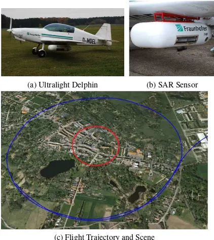
Height above Ground 600−800m
Radius 640m
Flight Velocity 30−35m/s
Depression Angle 30◦(±5◦) Roll Angle (ideal) 12◦ Mean Target Range 1200m Carrier Frequency 35GHz Signal Bandwidth 1GHz Azimuth Beamwidth 3◦
Table 1. Flight and Sensor Parameter.
(a) Ultralight Delphin (b) SAR Sensor
(c) Flight Trajectory and Scene
Figure 1. Circular flight trajectory.
3. SAR PROCESSING CHAIN
Airborne SAR datasets that are acquired over a circular trajec-tory are of special interest for three main reasons. First, the infor-mation of different azimuthal directions together with the use of radargrammetric methods can be matched to obtain 3D informa-tion over the scene of interest (Palm et al., 2012). Second, when the target scene can be illuminated under a full360◦aperture and the data can be coherently processed, even subwavelength reso-lution is theoretically feasible (Ishimaru et al., 1998). Both of these applications require a certain homogeneity of target reflec-tivity which is usually non-existent in unknown urban scenarios as shadow and overlay areas usually change dependent on the as-pect angle. Further, full coherent processing of the radar raw data over a full360◦circular trajectory places very high demands on the inertial measuring unit (IMU) of the system which might be problematic. The raw data processing thus depends on the spe-cific application.
This research focuses on the third feature, which is to nonco-herently reconstruct an unknown urban area scenario by multiple
should will provide an unobstructed view of these scenes. The same is true for any course of a road as there will be a line of sight - out of a full circular dataset - which is best fit, provided that the change of the aspect angle between two images is very small.
The sensor’s radar waveform has a given bandwidthBW of 1 GHz, thus corresponding to a range resolution of 15 cm. The azimuth resolution, in contrast, depends on the wavelength of the system and the ability to illuminate and coherently process a given target on the ground in a preferably high angular interval. The sensor, Miranda, is working at a center frequency of 35 GHz in Ka-Band. For sufficiently small angles in the ideal side look-ing stripmap geometry, the azimuth angular intergration interval
φcan be approximated as:
φ= f0
BWAzimuth
(1)
wheref0is the corresponding center frequency andBWAzimuth is the desired bandwith in azimuth. Thus to achieve a correspond-ing azimuth resolution of 15 cm, an angular interval ofφ= 1.5◦ in azimuth direction must be coherently processed. With a typical flight height of 600 - 800 m, this leads to a synthetic aperture of ˜ 40 m corresponding to ˜ 0.8 seconds, which is very short. It is important to note, that the integration intervallφis propor-tional to the center frequencyf0of the used radar system. Espe-cially for airborne SAR on circular trajectories in urban scenar-ios, this becomes very interesting, as the illumination intervall for given objects on the ground might be very short. A small street between high buildings or parked cars next to buildings might only be seen for a very short moment in a very small aspect an-gle. Shortly thereafter, it may already be covered again by other buldings or structures. Small scale structures like chimneys or so-lar panels are simiso-lar and characteristically flash brightly only for very limited aspect angles. As a digital elevation model (DEM) or a digital surface model (DSM) is not currently in use, blur-ring or artifacts in the focusing process caused by foreshortening effects or assuming the wrong ground height are less significant than when using lower frequencies. The advantage of high radar center frequencies in this case lies in the fact that only short syn-thetic apertures corresponding to little aspect angle change need to be coherently processed to obtain high resolution in azimuth direction.
3.1 SAR Focusing
Figure 2. Circular SAR Geometry - Construction of 3D image stack for each different aspect angleϕ.
dimensional image stack leading to a characterisation where each pixel is represented by its look-angle as well as its phase and amplitude value, see figure 2. Each point scatterer at position (¯x,y,¯ z0¯)withz0¯ being the focussing plane height is mapped to the image coordinates(x, y)and can thus be characeterized by a matrix of amplitudes and phase information for every aspect angleϕfor which it was illuminated.
(¯x,y,¯ z0¯)→(x, y;σ1, θ1, ϕ1),in linear mode (2)
(¯x,y,¯ z0¯)→(x, y;σ1...n, θ1...n, ϕ1...n),in circular mode (3)
where x,¯ y,¯ z0¯ = scatter coordinates
x, y= image coordinates
σ= scattering amplitude
θ= scattering phase
ϕ= aspect angle
n= number of looks
The generated SAR image stack over the entire trajectory finally consists ofn= 240individual SAR images, each visualizing the scene from a slightly different aspect angle.
3.2 Flight Parameters
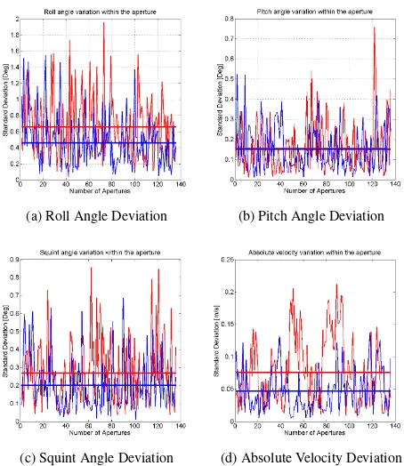
To evaluate the increased demands on the SAR processing steps, angle and velocity IMU data from a linear flight and a circular flight are compared. These data are helpful for choosing appro-priate SAR focussing algorithms as well as defining requirements for potential mechanical or electronical beam stabilization mea-sures. The IMU data displayed in figure 3 and 4 are limited to 110 seconds due to the limit of the linear flight tracks, which are relatively short compared to the circular tracks. The position an-gles Roll, Pitch and Squint are presented along with the absolute velocity of the airplane. Data from linear flight path is visualized in blue, and data from circular trajectory in red. As expected, the absolute values in figure 3 show the circular trajectory is much more volatile than the linear flight track. As can be seen in figure 1c, the pilot was able to fly a relatively accurate circle. Ideally, without any turbulences, this would have been done with a mean roll angle of−12◦. However, to compensate for drift movements, data shows that especially roll and squint angles have strong fluc-tuations during the measurment. Roll angle varies between0◦ to−30◦while squint varies between−13◦to+10◦. The same is true for the absolute velocity parameter, only the pitch angle
(a) Absolute Roll Angle (b) Absolute Pitch Angle
(c) Absolute Squint Angle (d) Absolute Velocity
Figure 3. Selected navigational data from flight measurement. Circular trajectory is marked in red, linear trajectory is marked in blue. Represented are 110 flight seconds, corresponding to 7000 data packages.
(a) Roll Angle Deviation (b) Pitch Angle Deviation
(c) Squint Angle Deviation (d) Absolute Velocity Deviation
data within a single synthetic aperture. These values are impor-tant for the focussing process as - in contrast to figure 3 - a high volatility will cause blurring effects or lower the signal to noise ratio in the coherent processing. At an IMU data rate of 64 Hz a typical synthetic aperture consists of roughly 50 data packages. Within these packages the standard deviation is calculated and plotted in figure 4. The horizontal line corresponds to the mean deviation over the dataset. Again, as expected, the circular flight path is noticeably unstable, especially roll and squint angle. The deviation for these two angles is40%higher on average in the cir-cular mode. As the volatility in the roll angle only leads to a de-crease in signal to noise ratio for far and near range, which might be bearable, the high volatility in the squint angle will cause blur-ring effects and should therefore be compensated properly.
(a) Corner Reflector (b) Point Target Response
Figure 5. Focused corner reflector and point spread function from the circular dataset. Measured range resolution of 16 cm (blue) and even better in azimuth (red).
4. SCENE RECONSTRUCTION
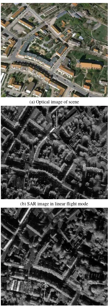
Figure 6 shows the optical image of the urban scene. Below, the resulting SAR images from the two opposing linear flights are presented. The resolution is 15 cm, and the line of sight is in-dicated by white arrows. The proportion of shadow areas and the potential misinterpretation caused by foreshortening effects is typical for urban scenarios.
Figure 7 shows the build up of the scene by the use of circular trajectories. Each independent SAR image stripe visualizes the illuminated scene from a different aspect angleϕ. The complete scene can be reconstructed step-by-step. The results of the inde-pendent images in figure 7 are very promising. Although there is no beam stabilization so far, the images are sharply focused and even fine structures are visible. This is further confirmed by fig-ure 5 showing the point target response of a single corner reflector placed in the scene. The resolution of the point spread function with 16 cm is close to the theoretical expectation.
As long as the ground plane is estimated at the correct height, and the scattering elements are present at the focussing heightz0¯, the individual pixels in the image stack show no geometric dis-tortions, and the difference within the images is only due to the changing reflectivity caused by the moving aspect angle. How-ever, the greater is the aspect angle difference and the higher is the true altitude of the reconstructed building the more unfamil-iar the impression for the observer is when mixing information of different aspect angles to one final resulting image. Shadow
(a) Optical image of scene
(b) SAR image in linear flight mode
(c) SAR image in linear flight mode, opposite direction
Figure 6. Optical and SAR image of urban scene. Line of sight is indicated by arrow. Images are processed in linear flight mode.
areas in one look angle can be identified and may be replaced by information from a different aspect angle but foreshortening effects may also reverse, overlaying areas which could be cleary recognised before. Overlaying of high structures will therefore cause distortions as the perspective views do not match.
appro-(a)ϕ= 70◦ (b)ϕ= 95◦ (c)ϕ= 110◦
Figure 7. SAR image stripes taken from the image stack and processed from different aspect anglesϕ.
priate aspect angleϕof the radar line of sight can be calculated. Typically, the best radar line of sight is parallel to the street di-rections. This allows a direct view into the street parallel past the buildings. Having this information the scene is then recon-structed by multiple sights, matching the radar line of sight with the street direction. Each view now only shows the course of the street and close neigborhood. Figure 9b indicates the line of sight for each SAR stripe in the full image by arrows. Different SAR image stripes are separated by different colors. Except for a small part of the street, which could not be illuminated in a par-allel angle, all other parts are recognisable and free of shadow and foreshortening effects. Parked cars, even next to buildings, are thus identifiable. Even if the perspective might be confusing in some parts, a complete view of all streets is given in just one image.
5. MOVING TARGETS IN IMAGE STREAM
(a) (b)
(c) (d)
(e) (f)
(g) (h)
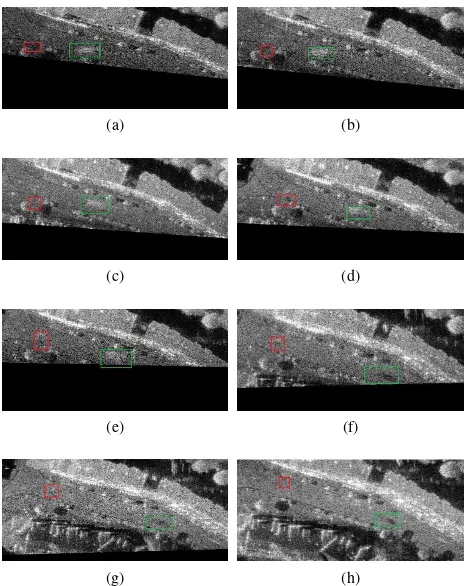
Figure 8. Detailed sequence of 8 consecutively recorded images (a-h) with slightly changing aspect angles, covering the street and intersection. Shadow of pedestrian crossing the intersection (red) and car moving along the street (green) is visible in moving im-ages.
(a) SAR image composed of different aspect angles views
(b) SAR image composed of different aspect angles views
Figure 9. Complete view on urban street scenario. SAR image composed of different aspect angles views. Each line of sight of the partial SAR image strip is indicated by arrows. Different SAR image stripes are separated by different colors. Only minor areas still show foreshortening or shadow effects as a satisfactory illumination angle was not collected during the circular flight tra-jectory. Parked cars are indicated in green. Different perspectives in the final image may be confusing.
the object is mapped at the correct image position and becomes visible in successively recorded moving images. It can therefore easily be tracked. Figure 8 shows a sequence of 8 consecutively recorded images with slightly changing aspect angles. A driving car along the street is marked in green while a pedestrian crossing the intersection is marked in red. The shadow of the pedestrian is difficult to recognize in a still image, whereas, the shadow of the car and parts of the blurred backscattering signal is significantly more noticeable.
6. CONCLUSION
The data shows that a full aspect coverage of the scene is not yet possible, as the system does not currently have an electronically or mechanical radar sensor stabilization, which might compen-sate for any flight inaccuracy or turbulence. Due to the small radar beamwidth of3◦, there are still gaps left in the scene re-construction as the beam is continuously drifting out of the target area. Especially the unstable roll and squint angle cause problems in fixing the radar footprint on a defined scene. Nevertheless, the image quality on circular trajectories is not recognizably worse than flying in linear mode. Corner reflectors are focused close to theoretical values. First results on reconstruction methods of urban scenes with multiple aspect angles are demonstrated. A full view on a difficult urban street scenario revealing parked cars even besides higher buildings shows the potential of the data fu-sion. Generally, the more the aspect angles or the imaging ge-ometry between two SAR images varies, the higher amount of information is usually available. But the mixing of different per-spectives requires for advanced algorithms. Further potentials of such particular datasets like moving target indication are demon-strated as the shadow of moving cars or pedestrians on streets may be tracked using the consecutive image sequence that was generated.
REFERENCES
Cantalloube, H. and Colin, E., 2006. Airborne SAR imaging along a circular trajectory. In:EUSAR 6th. European Conference on Synthetic Aperture Radar, Dresden.
Cantalloube, H. M. J., Colin-Koeniguer, E. and Oriot, H., 2007. High resolution SAR imaging along circular trajectories. In: Geoscience and Remote Sensing Symposium, 2007. IGARSS 2007. IEEE International, pp. 850–853.
Frey, O., Magnard, C., Ruegg, M. and Meier, E., 2009. Focusing of airborne synthetic aperture radar data from highly nonlinear flight tracks.Geoscience and Remote Sensing, IEEE Transactions on47(6), pp. 1844–1858.
Ishimaru, A., Chan, T.-K. and Kuga, Y., 1998. An imag-ing technique usimag-ing confocal circular synthetic aperture radar. Geoscience and Remote Sensing, IEEE Transactions on36(5), pp. 1524–1530.
Kinghorn, A. and Nejman, A., 2009. PicoSAR- an advanced lightweight SAR system. In: Radar Conference, 2009. EuRAD 2009. European, pp. 168–171.
Geoscience and Remote Sensing, IEEE Transactions on50(11), pp. 4720–4725.
Palm, S., Wahlen, A., Stanko, S., Pohl, N., Wellig, P. and Stilla, U., 2014. Real-time onboard processing and ground based mon-itoring of FMCW-SAR videos. In:EUSAR 2014; 10th European Conference on Synthetic Aperture Radar; Proceedings of, pp. 1– 4.
Ponce, O., Prats, P., Rodriguez-Cassola, M., Scheiber, R. and Reigber, A., 2011. Processing of Circular SAR trajectories with Fast Factorized Back-Projection. In: Geoscience and Re-mote Sensing Symposium (IGARSS), 2011 IEEE International, pp. 3692–3695.
Ribalta, A., 2011. Time-Domain Reconstruction Algorithms for FMCW-SAR. Geoscience and Remote Sensing Letters, IEEE 8(3), pp. 396–400.
Ruault du Plessis, O. and Dreuillet, P., 2013. The ONERA air-borne multi-frequency SAR imaging systems. In:Radar (Radar), 2013 International Conference on, pp. 85–90.
Schmitt, M. and Stilla, U., 2011. Fusion of airborne multi-aspect InSAR data by simultaneous backward geocoding. In:Proc. Joint Urban Remote Sensing Event (JURSE), pp. 53–56.
Soumekh, M., 1996. Reconnaissance with slant plane circular SAR imaging. Image Processing, IEEE Transactions on5(8), pp. 1252–1265.
Stilla, U. and Hedman, K., 2010. Feature Fusion Based on Bayesian Network Theory for Automatic Road Extraction. Dor-drecht: Springer, pp. 69–86.