3D DIGITIZATION OF MUSEUM CONTENT WITHIN THE 3DICONS PROJECT
S. Gonizzi Barsanti a,*,G. Guidi aa
Dept. of Mechanics, Politecnico di Milano, Via la Masa, 1, Milano, Italy (sara.gonizzi, gabriele.guidi)@polimi.it
KEY WORDS: Image Based Modelling, Structure from Motion, Digital Heritage, 3DIcons, Europeana.
ABSTRACT:
The main purpose of the European Project “3DIcons” is to digitize masterpieces of Cultural Heritage and provide the related 3D models and metadata to Europeana, an Internet portal that acts as an interface to millions of books, paintings, films, museum objects and archival records that have been digitised throughout Europe. The purpose of this paper is to define a complete pipeline which covers all technical and logistic aspects for creating 3D models in a Museum environment with no established digitization laboratory, from the 3D data acquisition to the creation of models that has to be searchable on the Internet through Europeana. The research group of Politecnico di Milano is dealing with the 3D modelling of the Archaeological Museum of Milan and most of its valuable content. In this paper an optimized 3D modelling pipeline is shown, that takes into account all the potential problems occurring during the survey and the related data processing. Most of the 3D digitization activity have been made exploiting the Structure From Motion (SfM) technique, handling all the acquisition (e.g. objects enlightenment, camera-object relative positioning, object shape and material, etc.) and processing problems (e.g. difficulties in the alignment step, model scaling, mesh optimization, etc.), but without neglecting the metric rigor of the results. This optimized process has been applied on a significant number of items, showing how this technique can allow large scale 3D digitization projects with relatively limited efforts.
1. INTRODUCTION
The 3D Icons project is funded under the European Commission’s ICT Policy Support Program which builds on the results of CARARE and 3D-COFORM*. The project is still active and will end in February 2015.
The project brings together 16 partners from across Europe (11 countries) with relevant expertise in 3D modeling and digitization. Its goal is to provide Europeana with 3D models of architectural and archaeological monuments and buildings identified by UNESCO as being of outstanding cultural importance. The main purpose of this project is to produce accurate 3D models (around 4000) that have also to be generated in simplified form in order to be viewable on low-end personal computers. For reaching this goal a suitable pipeline of surveying and modeling have to be outlined, together with a metadata schema for both the information about the monuments or objects surveyed and the techniques used.
The research group of Politecnico di Milano (POLIMI) has to deal with the roman structures of the circus that are now included in the modern building representing the Milan Archaeological Museum (MAM), including all archaeological objects stored inside it, for a total of 527 models to be created. Two different techniques were used: i) laser scanning for the 3D survey of the archaeological remains; ii) Structure From Motion (SfM) for the objects. This paper describes the workflow adaptation implemented by the POLIMI unit for optimizing the latter part of their task.
It was decided to avoid laser scanning for the archaeological items because i) their material (marble, glass, bronze etc.) resulted less optically cooperative with laser than with digital photography; ii) the highly texturized surfaces of some archaeological objects may generate significant 3D artifacts with triangulation laser scanners; iii) the generation of a texturized mesh model has been demonstrated to be far more time consuming capturing the shape with an active device and
*
http://www.3d-coform.eu/
texturing it with photos, rather than generating shape and texture in the same process with SfM (Fassi et al., 2013).
2. THE ARCHAEOLOGICAL MUSEUM AND ITS COLLECTION
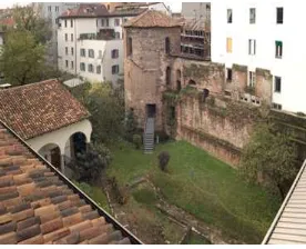
The archaeological museum is literally built upon strata of history coming from the fact that Milan has been capital of the Western Roman Empire for more than one century (from 286 to 402 A.D.). The most recent architecture belongs to the Monastery of San Maurizio, from the XVI century, having underneath the mediaeval monastery, built in the VIII century. The medieval monastery was built itself on the remains of the Roman circus dated back to the IV century A.D. and of the city walls, from which two towers are still visible. The circus tower, preserved to a height of 14 meters and integrated into the VIII century monastery as a bell tower, has been subjected to several changes across the centuries, but it still conserves structures of the Roman period. During horse races, the horses departed from this point and then went around the interior of the circus seven times before arriving at the winning post. In the museum gardens a polygonal tower, with 24 faces, is conserved, related to the city walls, enlarged by emperor Massimiano at the end of the III century A.D (Fig.1).
Figure 1 The archaeological remains of the Roman Circus enclose the courtyard of the Archaeological Museum in Milan.
(Courtesy of MAM)
The most ancient stratum of history underneath the archaeological museum goes back to the I century A.D. Remains of Roman houses are still visible nowadays, in the second cloister of the museum.
The museum held more than 1000 archaeological objects from different historical periods, Greek, Etruscan, Roman, Medieval. Epigraphs stand as some of the most important sources for the understanding of a historical time; statues, most of which actually were recycled and reused as building blocks, show centuries of art and history; mosaics in the ancient Roman houses were appreciated not only for aesthetic reasons, but were also an indicator of the social status of their owners; furniture made in glass, silver, bronze, and pottery complete the exposition with very important pieces as the glass cup called Diatreta and a silver plate called the Patera di Parabiago (Fig.2).
Figure 2 One of the room of the Museum (above) and the Diatreta (below). (Courtesy of MAM).
3. DATA COLLECTION
For 3D modelling the archaeological objects it was decided to test the SfM technique. For image acquisition a Canon 5D Mark II (Full Frame), a Canon 60D and a Sony NEX5 both mounting an Advanced Photo System type-C format (APS-C) were used, smaller than full frame (see Fig. 5 for a detailed format comparison). By now 406 images were acquired with the Sony camera, 760 with the Canon 60D and 43 with the Canon 5D, in total 1183 images for 14 models produced. The Sony NEX5 is a 16 megapixel camera with a 23.5×15.6mm CMOS sensor coupled with 16 mm lens; the Canon 60D is a 18 megapixel camera with a 22.3 x 14.9mm CMOS sensor coupled with 20 and 50 mm lenses and the Canon 5D features 22 megapixel with a 36 x 24mm CMOS sensor coupled with a 20 mm lens. The images were acquired at the highest level for each camera (5616 x 3744 pixels for the 5D, 5138 x 3456 pixels for the 60D and 4912×3264 for the NEX5) in JPEG format; such choice was due to limitations of the software used for the SfM processing, capable to open only JPG images (not RAW). The distance to which the images were taken was variable (0.5-3m) due to the disposition of the objects in the Museum: some of them were halted to the walls and was not possible to move
them. The images were taken maintaining around 60% of overlapping between adjacent images.
3.1 The survey
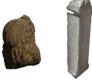
The Archaeological Museum is organized in thematic rooms, one for each historical period, with the roman age covering the low ground floor and the two courtyards, the mediaeval period on the first floor, the Etruscan one on the second and finally the Greek one on the top floor. Some objects are fixed on pillars or to the walls, other are movable or in glass display cases. The rooms illumination is based on spotlights pointed directly on the artefacts. The ground floor is also illuminated by a big glass wall closing the room on one side. During the survey, the logistics strongly influenced the image acquisition. For the objects blocked it was quite impossible to catch the entire surface with images. As a consequence the final mesh originated by SfM applied on the only images available, were characterized by holes and gaps (Figs. 3 and 4).
The illumination gave other problems, due to the changes in the colours of the object itself. For the objects fixed or installed close to the walls, nothing can be done to acquire their whole surface, producing therefore a complete model. But, if this is not so problematic with flat elements, as steles or inscriptions, that have nothing behind except a rough surface that in the digital model can be easily replaced with a plan, on the other hand it’s obviously an important issue with sculptures in the round. In this cases the model can be closed for aesthetical reasons, but of course something false respect to the original has to be added (Fig.4).
Figure 3 Two examples of objects blocked on a wall: a head (left) and a stele (right).
Figure 4 The differences between the two models: if for the stele the gap is not problematic because the rear part is flat and
empty, for the head it’s necessary to complete the model by hand, without real data.
Another problem occurred during the shooting, related to the logistic and to the blocked position of some objects, was the use of the right lens to be used. In some cases, the items were really near the walls, so that was difficult to stand at the suitable distance to acquire the images. In these cases the pipeline was organized with respect to the type of the camera and its specification.
Except for macro lenses the image on the sensor is always smaller than the real object and it is (approximately) proportional to the focal length used: this means that a 20 mm on a full frame camera focuses a larger part of the object than it does the same lens on a APS-C camera: on these kind of cameras, in order to have the same image size as the one taken with a full frame one, it is necessary to multiply the value of the focal of the lens by 1.6 (Tab.1). This depend on the size of the sensor that is 36 mm x 24 mm on full frame and becomes 22.2 mm x14.8 mm on APS-C cameras (Fig. 5).
Actual focal length (mm)
Equivalent focal length for an APS-C camera (mm)
20 32
50 80
70 112
115 184
Table 1 The same lens mounted on full frame camera gives a viewing angle on an APS-C camera equivalent to a longer lens.
Figure 5 Sensors size for different camera models and brands.
Figure 6 Images of two statues very close to a wall, taken with an ASP-C camera equipped with a 50mm lens.
On the other hand, the 50 mm was totally useless for unmovable objects. In this case the framed portion of the whole object could be too small due to distance constraints of the shooting
position, and it may be necessary to acquire a redundant number of images than otherwise needed, influencing the result of the final model (Fig. 6).
To know exactly the difference in framing the objects or part of them with different cameras coupled with different lenses, there’s a web site that can be useful, DOFmaster, whose name comes from Depth Of Field (DOF). As a matter of facts it is possible to set the camera model (i.e. the sensor size), the focal length, the pupil size, the distance from which the image will be acquired and have, as a result, the depth of field (Fig. 7).
Figure 7 Comparison between the DOF of a full frame and an ASP-C camera coupled with the same lens, taking images 2 m far from the object. For the same relative circle of confusion
(8.5e-4) the DOF changes from 11.4m to 2.97m.
The illumination of course also influences the survey, especially when spotlights are directly oriented toward the object. In this case the illuminating conditions may prevent the automatic algorithm to identify corresponding portions of the object. A big problem was the possible presence of windows that created a significant backlight effect compromising sometimes the shots. The solution in those cases was to use a flat panel to shield the backlight avoiding the strong light imbalance and the relatively dark foreground (Fig.8).
Figure 8 The changes in enlightenment between two images of the same objects acquired from different points of view.
4. DATA PROCESSING
The data processing was carried out with the Agisoft Photoscan* package, a semi-automatic software in which both the camera orientation and the internal calibration are made, allowing little interaction to the user. Some choices can be done during image orientation, where the operator may set: i) alignment accuracy level; ii) possible control points; iii) image masking for hiding possible misleading portions of the area surrounding the main subject.
At mesh generation stage the software permits to decide the accuracy and the polygon number of the final 3D model. The software implements image orientation and mesh generation through SfM and dense multi-view stereo-matching algorithms (Exact, Smooth, Height Field and Fast).
4.1 The mesh model generation
The first step in the process is image masking, for preventing the software from using and catching points around the main subject that might produce a bad alignment and a low quality mesh (Fig. 9).
a)
b)
c) d)
Figure 9 Comparison between orientations of the same images with or without masking: a) alignment points with no mask. Several elements not related with the main subject influence the
processing; b) definition of the mask; c) alignment points after masking; d) final model generated with masks.
*
http://www.agisoft.ru/
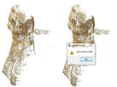
All the problems occurred during the survey step, of course influenced also the following data processing. The camera and appropriate lens selection were easily carried out after a few tests on the same objects acquired with different settings, for understanding the best set up. As a software derived from the SfM philosophy, Agisoft works better with many images taken with a short baseline rather then few images with a relatively long baseline as in standard photogrammetry. This involves a significant overlapping among images that eases the automatic image matching, preferably on more than two images. In situations where the narrow viewing angle and the environmental constraints imposed strong limitations in the shooting position, the software had problems in finding the homologous points and the alignment was not satisfactory and prevented the following mesh generation. (Fig.10).
Figure 10 The problems during the alignment process using images acquired with a non correct set up of the equipment.
About the illumination contrasts it was decided to use shielding panels to avoiding backlights and reflecting panels to make more homogeneous the object lightening by brightening the darker shades. During the 3D processing it was found that the excessively dark shadows on the objects influenced the results creating a rough surface. Where a better lightning was not available, the only possibility for obtaining a better result was to use the “smooth” geometry processing (Fig. 11).
a) b)
Figure 11 Agisoft mesh generation with: a) bad illumination and standard processing; b) same illumination and “smooth”
mesh processing.
4.2 Processing pipeline suitable for museum artefacts
Several tests were done using items different in shape, position and size, to test the software potential with this kind of objects and the best pipeline for producing a huge amount of accurate model in the shortest possible time frame. The first step was, as seen, a suitable image masking to reduce both the number of pixel processed (i.e. the workload) and the possible interference of surrounding elements in the scene on the main subject. A better calibration and orientation was proved setting the accuracy parameter to “high”, in change of an increase of the processing time.
After the image orientation, the mesh generation was made with the parameters defined as in Figure 12. The only floating parameter was the “geometry type” that was established to be changed according to the type of object to be modelled. The object type “Arbitrary” defines a 3D free form (Choen et al., 2012; Pollefeys et al., 2000) or “Height Field”, namely a 2.5D surface like a DTM (Doneus et al., 2011; Verhoeven et al., 2012) The “geometry type” can be set as sharp or smooth depending also on the shape of the object to be modelled. The “target quality” specifies the desired mesh quality: higher quality settings can be used to obtain more detailed and accurate geometry, but require longer time for processing. “Face count” specifies the maximum number of polygons in the final mesh and 0 indicates that no decimation is set. The “filter threshold” specifies the maximum face count of small connected components to be removed after surface reconstruction (as percentage of the total face count). The 0 value disables connected component filtering.
Figure 12 The parameters set for the creation of the mesh.
The Target quality was set on medium after the comparison of two models, one processed setting “high” quality, the second with “medium” quality (Fig. 13). In our test the differences for a stone object 1.5m long were all inside the range 0.1-0.5 mm. It was therefore considered acceptable to generate the mesh with a “medium” target quality, that resulted much less time consuming.
Figure 13 Comparison between two model of the same object setting as reference the high quality target model and as data the
medium one.
After these tests it was possible to define a summary table (Table 2) with the differences in the processing time using the same images and alignment on the same computer for different types of objects. As long as the final purpose of the project is to collect a huge amount of 3D models manageable on the internet, the medium quality seems the best option in terms of quality, time in the processing and final texturized result.
Object Target quality High
Target quality Medium
Computer
Statue
˜
4 hr˜
2 hrQ-Core Laptop 16 Gb Ram Head
˜
2 hr˜
45 min Q-Core Laptop 16 Gb Ram Bronzevase
˜
3 hr˜
1 hrQ-Core Laptop 16 Gb Ram Pottery
˜
2 hr˜
45 min Q-Core Laptop 16 Gb RamTable 2 Differences in the processing time between the high and the medium target of same objects on the same computer.
With these parameters, the results were high polygons meshes with a good accuracy. After the processing with Agisoft, the models were saved with image texture (arranging the image as 4096x4096 pixel) in obj format. The result was then imported in Polyworks* to correct possible topologic errors and to close gaps and lacking data omitted due to the environmental constraints. Finally a polygon decimation was made for avoiding excessive polygon densities for flat or smooth geometries as naturally generated by the image matching stage (Fig.14).
Using the above mentioned pipeline, it was possible, starting from March, to produce more than one hundred texturized 3D model, more or less 30/40 model a months, ready for the data entry in Europeana.
*
http://www.innovmetric.com/polyworks/3D-scanners/home.aspx?lang=en
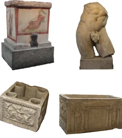
Figure 14 Four final models of different items stored in the Museum: an altar, a statue of Heracles, an angular piece of a
public building, re-used several times, and a sarcophagus.
5. METADATA COLLECTION AND PROBLEMS
The final goal of the 3D Icons project is, as said, the collection of 3D models and their metadata to be put in Europeana. The acquisition and the successive implementation with metadata is something that is not precisely defined yet. It was decided to follow the CARARE schema, adopting the CARARE organization in labels and fields*.
There are three different levels in the collection of metadata inside the project: some partners have already put in CARARE some information, others (as POLIMI) has sheets and metadata from other sources but nothing inside CARARE, and finally some partners that don’t have neither metadata nor something in CARARE. Is now under developing a tool that will permit the implementation of data in CARARE, with both the information about the object modelled and the technique used (e.g. which type of laser scanner or camera, the resolution, the GSD etc.). Regarding the objects metadata, the POLIMI’s research team will use the SIRBeC (Information System of Cultural Heritage of the Lombardia Region) data sheets**. SIRBeC is the cataloguing system of Cultural Heritage spread on the regional territory or preserved in museums, libraries and other cultural institutions. In these data sheets every kind of information about an object is included, as description, material, dating, place of discovery, place of conservation, if the object belonged to a specific monument or building and so on. The next step will be choosing the information mandatory in CARARE, creating a compatible file and insert everything in this metadata schema.
6. CONCLUSIONS
As a pilot project for the implementation of Europeana with 3D models, the 3D Icons project is permitting to test the techniques available on different objects, situations and materials. Having
the necessity to produce a high number of models in three years, it was essential to organize the work in a strict pipeline that permitted to avoid time consuming operations. That’s why the laser scanning was not taken into account, except for particular objects made for example in silver, very reflective, or with low texture: in these cases, the laser scanner will be used because the photogrammetric technique is not the best choice with these type of materials. Another reason why the laser scanning was not and will not be used as the main technique is because, among the objects, a huge number is made of small, high detailed items that will be tough to acquire.
Within this project there was also the possibility to test the Agisoft Photoscan software that seems to be a very good product for generating good quality meshes from images in a semi-automatic way, giving the possibility to avoid manual selection of homologous points as in traditional photogrammetry, but permitting an acceptable interaction with the user.
7. ACKNOWLEDGMENT
The authors want to thank the director of the Archaeological Museum of Milan Dr. Donatella Caporusso for authorizing the surveys, all the staff at the Museum to be so kind in helping and Dr. Laura Micoli for her support in testing Agisoft and during the surveys at the Museum.
8. REFERENCES
Cohen, A., Zach, C., Sinha, S., Pollefeys, M., 2012. Discovering and exploiting 3D symmetries in structure from motion. In: Proc. IEEE Int. Conf. on Computer Vision and Pattern Recognition, pp.1514-1521
Doneus, M., Verhoeven, G., Fera, M., Briese, Ch., Kucera, M., Neubauer, W., 2011. From Deposit to Point Cloud – A Study Of Low-Cost Computer Vision approaches for the straightforward documentation of Archaeological Excavations.
Geoinformatics CTU FCE, pp. 81-88
Fassi F., Fregonese L., Hackermann S., De Troia V., 2013. Comparison between laser scanning and automated 3D modelling techniques to reconstruct complex and extensive Cultural Heritage areas. In: ISPRS 3DArch, Trento, Italy, Vol. XL-5/W1, pp. 73-80.
Pollefeys, M., Vergauwen, M., Van Gool, L., 2000. Automatic 3D modelling from image sequences, invited presentation. In: International Archive of Photogrammetry and Remote Sensing, Vol. XXXIII, Part B5, pp. 619-626
Verhoeven, G., Doneus, M., Briese, Ch., Vermeulen, F., 2012. Mapping by matching: a computer vision-based approach to fast and accurate georeferencing of archaeological aerial photographs. Journal of Archaeological Science 39, pp. 2060-2070