BAB III
KONFIGURASI SISTEM
3.1
CPM2A-30 or 30 I/O CDR
Komponen-komponen dari CPU CPM2A seperti ditunjukan pada gambar dibawah
3.2 CPM2A-40CDR
3.3 CPM2A-60CDR
3.4
CPU dan Expansion I/O Unit Configuration
Spesifikasi Komponen PLC Omron Jenis CPM1A / CPM2A
1) Spesifikasi Umum Dari Unit CPU Jenis CPM1A
Tabel dibawah menggambarkan 6 CPU CPM1A. Semua keluaran adalah Relay
output
Number of
I/O Terminal
Inputs Outputs
Power
Supply
Model number
AC
CPM1A-10CDR-A
10
6 points
4 points
DC
CPM1A-10CDR-D
AC
CPM1A-30CDR-A
20
12 points
8 points
DC
CPM1A-30CDR-D
AC
CPM1A-30CDR-A
30
18 points
12 points
DC
CPM1A-30CDR-D
AC
CPM1A-40CDR-A
40
34 points
16 points
DC
CPM1A-40CDR-D
Tabel dibawah menggambarkan CPM1A. Expansion I/O keluaran adalah Relay
output
Number of
I/O Terminal
Inputs Outputs Model
number
30
13 point
8 point
CPM1A-30EDR
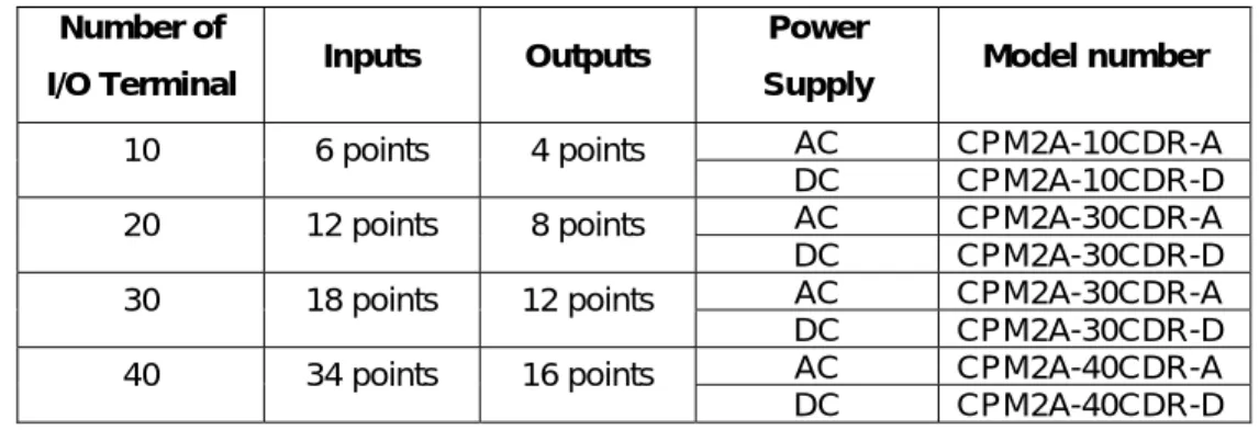
2) Spesifikasi Umum Dari Unit CPU Jenis CPM2A
Tabel dibawah menggambarkan 6 CPU CPM1A. Semua keluaran adalah Relay
output
Number of
I/O Terminal
Inputs Outputs
Power
Supply
Model number
AC
CPM2A-10CDR-A
10
6 points
4 points
DC
CPM2A-10CDR-D
AC
CPM2A-30CDR-A
20
12 points
8 points
DC
CPM2A-30CDR-D
AC
CPM2A-30CDR-A
30
18 points
12 points
DC
CPM2A-30CDR-D
AC
CPM2A-40CDR-A
40
34 points
16 points
DC
CPM2A-40CDR-D
3) Karakteristik CPU-CPM1A/ CPM2A
Adapun karakteristik spesifik dari CPU-CPM1A/ CPM2A penjelasanya seperti
tertulis pada tabel dibawah ini.
Item
10 point I/O
20 point I/O
30 point I/O
40 point I/O
Control method Stored program methodI/O control method Combination of the cyclic scan and immediate refresh processing methods Programming language Ladder diagram
Instruction length 1 step per instruction, 1 to 5 words per instruction Types of Instructions Basic instructions: 14
Special instructions: 77 types 135 instructions Executions time Basic instructions: 0.72 to 16.2 µs
Special instructions: 12.375 µs (MOV instruction) Program capacity 2,048 words
CPU only 10 points (6 input/ 4 output) 20 points (12 input / 8 input) 30 points (18 input/12output) 40 points (24 input/16 output) Maximum I/O points With Expansion I/O unit --- ---- 99 points (54 input/36 output) 100 points (60 input/40 output)
Out bits 01000 to 01915 (words 10 to 19)
Work bits (IR area) 512 bits: IR 20000 to 23115 (Words IR 200 to IR 231) Special bits (SR area) 384 bits: SR 23200 to 25515 (words SR 232 to SR 255) Temporary bits (TR
area) 8 bits (TR0 to TR7)
Holding bits (HR area) 320 bits: HR0000 to HR 1915 (words HR 00 to HR 19) Auxiliary bits (AR area) 256 bits: AR 0000 to AR 1515 (Words AR 00 to AR 15) Link bits (LR area) 256 bits: LR 0000 to LR 1515 (Words LR 00 to LR 15)
Times/counters
128 times/counters(TIM/CNT 000 to TIM/CNT 127) 100-ms timers: TIM 000 to TIM 127
10-ms timers: TIM 00 to TIM 127
Decrementing counters and reversible counters Data memory Read/write: 1,024 words (DM 0000 to DM 1023)
Read-only: 512 words (DM 6144 to DM 6655) Interrupt processing 2 points (response time: 0.3 ms max) 4 points
(response time: 0.3 ms max)
Memory protection HR, AR, Data memory area contents and counter values maintained during power interruptions
Memory backup
Flash memory: User program, data memory (read only) ( Non- battery powered storage)
Capacitor backup: Data memory (Read/write), holding bits, auxiliary memory, counter (20 days at ambient temperature of 250 C) Self-diagnostic
functions
CPU failure (watchdog timer), I/O bus errors (continuously checked during operation)
Program check No END instruction, programming errors (continuously checked during operation)
High-speed counter 1 point: 5 kHz single-phase or 2.5 kHz two-phase (linear count method) Increment mode: 0 to 65,535 (16 bits) Up/Down mode: -32,767 to 32,767 (16 bits)
Quick-response inputs Together with the external interrupts inputs. (Min. pulse width: 0.2 ms) Input time constant Can be set to 1 ms, 2 ms,4 ms, 8 ms,16 ms, 32 ms, 64 ms, or 128 ms. Analog volume settings 2 controls (0 to 200BCD)
4) Struktur Area Memory PLC-CPM1A/ CPM2A
Dalam tabel berikut ini adalah merupakan struktur area memory dari PLC tipe
CPM1A/ CPM2A.
Data area
Words
Bits
Function
Input area IR 000 to IR 009 (10 words) IR 00000 to IR 00915 (160 bits) Output area IR 010 to IR 019 (10 words) IR 01000 to IR 01915 (160 bits)
These bits can be allocated to the external 1/O terminals. IR area1 Work area IR 200 to IR 231 (32 words) IR 20000 to IR 23115 (512 bits)
Work bits can be freely used within the program
SR area SR 232 to SR 255 (24 words)
SR 23200 to SR 25515
(384 bits)
These bits serve specific functions such as flags and control bits
TR area --- TR 0 to TR 7 (8 bits)
These bits are used to temporarily store ON/OFF status at program branches. HR area2 HR 00 to HR 19 (20 words) HR 0000 to HR 1915 (320 bits)
These bits store data and retain their ON/OFF status when power is turned off
AR area2 AR 00 to AR 15 (16 words)
AR 0000 to AR 1515 (256 bits)
These bits serve specific function such as flags and control bits
LR area1 LR 00 to LR 15 (16 words)
LR 00000 to LR 1515
(256bits)
Used for a 1:1 data link with another PC
Timer/Counter area2 TC 000 to TC 127 (timer/ counter numbers)3
The same numbers are used for both timers and counters DM area Read/write 2 DM 0000 to DM 0999 DM 1022 to DM 1023 (1,002 words) ---
DM area data can be accessed in word units only. Word values are required when the power is turned off
Error log4 DM 1000 to DM 1021 (22 words)
Used to store the timer of occurrence and error code of errors that occur. These word can be used as ordinary read/write DM when the error log function isn’t being used. Red – only4 DM 6144 to DM 6599 (456 words) Cannot be overwritten from program PC Setup4 DM 6600 to DM 6655 (56 words)
Used to store various parameters that control PC operation.